
www.fairchildsemi.com
REV. 1.0.2 12/17/03
Features
∑ Two independent outputs
∑ Load regulation: 0.05% typical
∑ Under-voltage lockout and softstart
∑ Over Temperature protection
∑ T0-252 DPAK, 5-lead SPAK packages
∑ Fixed 3.3V and adjustable or fixed 2.5V output
Applications
∑ Hard Disk Drives, CD-Roms
∑ Set-top Boxes
∑ ADSL line cards
∑ Motherboards with multiple supplies
General Description
The FAN1538 provides two output voltages: a fixed 3.3V
ouput and either a fixed 2.5V or adjustable output with 1A
output current capability. Refer to Ordering Information for
details.
Current limit protects against short circuit currents and on
chip over temperature circuitry limits the maximum die tem-
perature.
Under voltage lockout and softstart circuitry protects against
unregulated output voltages when the input voltage is below
specification.
Block Diagram
FAN1538B
V1
V2
FB
3.3V
V2 = VREF (1 + R1/R2)
at 1.0A
22
µF
1.5V at 1.0A
R2
1250
R1
250
22
µF
22
µF
22
µF
2.5V at 1.0A
3.3V at 1.0A
22
µF
VIN
= 5V
VIN
= 5V
+
+
V
IN
V1
NC GND
V2
FAN1538A
22
µF
+
22
µF
2.5V at 1.0A
3.3V at 1.0A
GND
+
22
µF
+
FAN1538
Dual Channel 1A Low Dropout
Linear Regulator with UVLO and Soft-start
FAN1538
PRODUCT SPECIFICATION
2
REV. 1.0.2 12/17/03
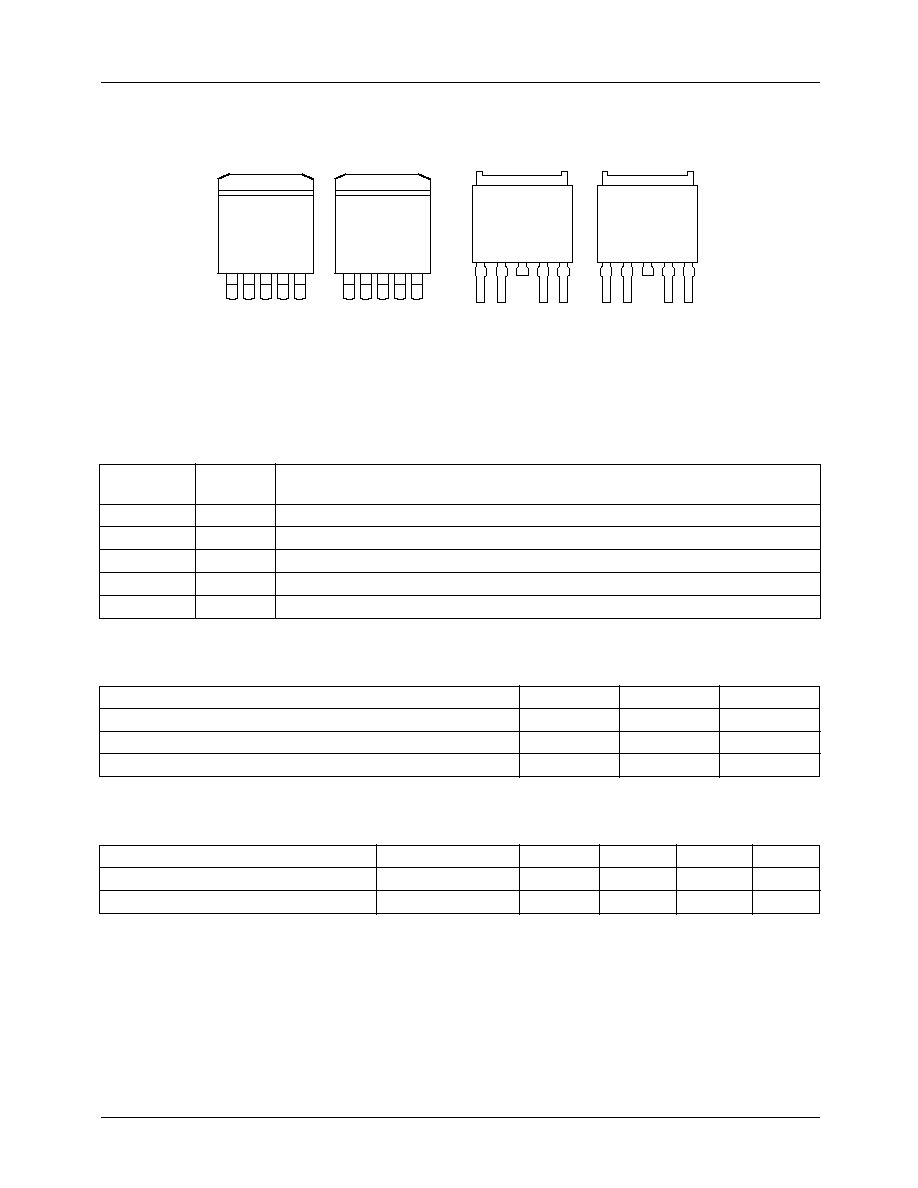
Pin Assignments
Pin Descriptions
Absolute Maximum Ratings
Recommended Operating Conditions
Pin Name
SPAK
DPAK
Pin Function
V
IN
1
Input supply voltage
NC/FB
2
For V2 fixed, no connect. For V2 adjustable, feedback voltage.
V1
4/5
Output #1
V2
5/4
Output #2
GND
3
Ground
Parameter
Min.
Max.
Units
VIN
10
V
Storage Temperature Range
-65
150
∞C
Lead Soldering Temperature, 10 seconds
300
∞C
Parameter
Conditions
Min.
Typ.
Max.
Units
VIN
Vin to GND
4.75
5
5.25
V
Ambient Operating Temperature (T
A
)
0
125
∞
C
1
2
3
4 5
FAN1538PB
FRONT VIEW
FB
V2
GND
V
IN
V1
5-Lead SPAK
JC
=2
∞C/W
FAN1538PA
FRONT VIEW
NC
V1
GND
V
IN
V2
NC
V1
GND
V
IN
V2
FB
V2
GND
V
IN
V1
5-Lead SPAK
JC
=2
∞C/W
1
2
3
4 5
FRONT VIEW
FAN1538DA
FRONT VIEW
FAN1538DB
5-Lead Plastic TO-252 DPAK
JC
=3
∞C/W Tab is GND
1
2
3
4
5
1
2
3
4
5

PRODUCT SPECIFICATION
FAN1538
REV. 1.0.2 12/17/03
3
Electrical Specifications
(Operating Conditions: VIN = 5V, TJ=25∞C unless otherwise specified)
The ∑ denotes specifications which apply over the full operating temperature range.
Diagram 1: UVLO and Softstart Timing
Parameter
Conditions
Min.
Typ.
Max.
Units
V1 Output Voltage
10mA
Iout
1A
4.50V
VIN
7V
∑
3.234
3.200
3.300
3.300
3.366
3.400
V
V2 Output Voltage (FAN1538A)
10mA
Iout
1A
4.50V
VIN
7V
∑
2.450
2.420
2.500
2.500
2.550
2.580
V
V2 Minimum Output Voltage
(FAN1538B)
10mA
Iout
1A
4.50V
VIN
7V
∑
1.400
V
Reference Voltage (FAN1538B)
(FB)
10mA<Iout<1A
4.50V
VIN
7V
∑
1.225
1.210
1.250
1.250
1.275
1.290
V
FB Pin Bias Current
∑
1
µA
Line Regulation
(Both Outputs)
4.50V
VIN
7V
Iout = 10mA
∑
0.005
0.5
%
Load Regulation
(Both Outputs)
VIN=5.0V
10mA
Iout
1A
∑
0.05
0.5
%
Current Limit
(Both Outputs)
VIN = 5V
1.1
1.5
A
Minimum Load Current
(Both Outputs)
4.50V
VIN
7V
∑
10
mA
Quiescent Current
VIN = 5V
∑
6
15
mA
Ripple Rejection
(Both Outputs)
F = 60Hz, Cout = 22µF
VIN = 5V, Iout =100mA
60
dB
Under-Voltage Lockout (See Diagram1)
VIN Rising threshold
∑
3.4
3.8
4.2
V
VIN Falling threshold
∑
3.0
3.3
3.6
V
V1 & V2 delay start time
VIN > UVLO Rising Threshold
150
µ
s
V1 softstart slew rate
250
µ
s/V
V2 softstart slew rate
R1 = 1250 & R2 = 250 ohms
550
µ
s/V
V1 & V2
VIN < 3.4
∑
0.5
V
Thermal Shutdown
Shut down Temperature
165
∞
C
Thermal hysteresis
40
∞
C
VIN
V3.3
VIN = 3.3V
V1.5
Time
Input
Voltage
150
µs
VIN = 3.8V
PRODUCT SPECIFICATION
FAN1538
REV. 1.0.2 12/17/03
4
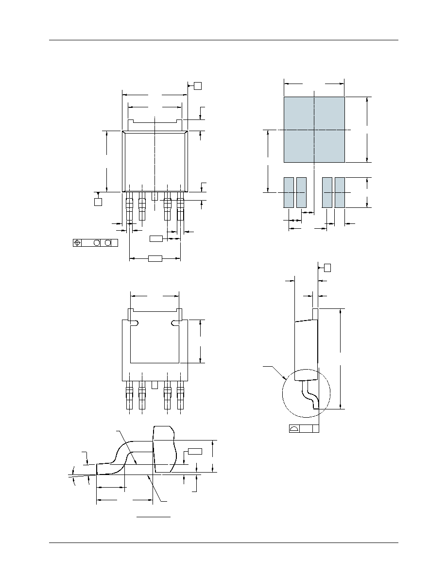
Mechanical Dimensions
TO-252 DPAK Package
(2.90)
10
∞
0
∞
1.78
1.40
GAGE PLANE
0.60
0.40
3
SEATING PLANE
0.13 MAX
(1.54)
1
2
0.51
(5.09)
(4.05)
SEE
DETAIL A
0.25 M
C
1
M C
A
1.27
0.50
1.02
0.60
4
2
5.64
5.04
1
6.25
A
2.40
2.18
B
0.10
10.42
9.20
0.60
0.40
3.00 MIN
B
6.56 MIN
6.00 MIN
3
5
0.57
±0.07
0.69
±0.15
1.27
5.08
5
4
6.80
6.35
6.30
5.90
3.81
1.00
(0.44)
1.27
1.27
LAND PATTERN RECOMMENDATION
NOTES: UNLESS OTHERWISE SPECIFIED
A) ALL DIMENSIONS ARE IN MILLIMETERS.
B) THIS PACKAGE CONFORMS TO JEDEC, TO-252,
ISSUE C, VARIATION AA, DATED NOV. 1999.
(ROTATED 90
∞)
SCALE: 2X
DETAIL A

PRODUCT SPECIFICATION
FAN1538
REV. 1.0.2 12/17/03
5
Mechanical Dimensions (continued)
5-Lead SPAK
L2
C
c1
c2
Seating Plane
0.005 (0.13)
0.001 (0.03)
R
Gage Plane
L1
5
1
B
A
L
D
b2
L3
M
0.010 (0,25)
0.004 (0,10)
3
∞≠6∞
Thermal Ta b
(See Note 3)
E
Notes:
1.
All linear dimensions are in inches (millimeters).
2.
This drawing is subject to change without notice.
3. The center lead is in electrical contact with the thermal tab.
4. Dimensions do not include mold protrusions, not to exceed 0.006 (0,15).
A
0.360
0.350
Symbol
Inches
Min.
Max.
Min.
Max.
Millimeters
Notes
B
0.220 NOM
0.268
0.070
C
0.080
c1
0.050
0.040
D
E
L
0.420
0.410
0.067
0.295 NOM
0
∞
8
∞
e
L1
c2
0.010 NOM
9.14
8.89
0.375
0.365
9.52
9.27
5.59 NOM
6.81
b1
b2
0.031
0.025
0.79
0.63
1.78
2.03
1.27
1.02
10.67
10.41
0.041
0.031
1.04
0.79
1.72
7.49 NOM
0.25 NOM
0
∞
8
∞
L2
0.360
0.350
9.14
8.89
L3
0.320
0.310
8.13
7.87
R
0.010 NOM
0.25 NOM
b1
e