Description
Features
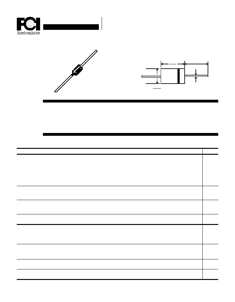
Mechanical Dimensions
Maximum Ratings
Peak Repetitive Reverse Voltage...V
RRM
RMS Reverse Voltage...V
R(rms)
DC Blocking Voltage...V
DC
SF61 . . . 66 Series
Average Forward Rectified Current...I
F(av)
T
A
= 55
∞
C
Non-Repetitive Peak Forward Surge Current...I
FSM
@ Rated Current & Temp
Operating & Storage Temperature Range...T
J
, T
STRG
Maximum Forward Voltage @ 6.0A...V
F
Maximum DC Reverse Current...I
R
T
A
= 25
∞
C
@ Rated DC Blocking Voltage
T
A
=100
∞
C
Typical Junction Capacitance...C
J
(Note 1)
Maximum Reverse Recovery Time...t
RR
(Note 2)
Page 4-30
Data Sheet
6.0 Amp SUPER FAST
PLASTIC RECTIFIERS
Units
Amps
Amps
∞
C
Volts
µ
Amps
µ
Amps
pF
ns
n LOW COST
n LOW LEAKAGE
n HIGH SURGE CAPABILITY
n MEETS UL SPECIFICATION 94V-O
SF61 . . . 66 Series
Volts
Volts
Volts
............................................. 6.0 ...............................................
............................................. 150 ...............................................
........................................ -65 to 150 .........................................
............................................. 5.0 ...............................................
............................................. 200 ...............................................
............................................. 170 ...............................................
< ......................... 0.95 ........................ > < ........ 1.4 ....... >
< ......................... 35 ........................ > < ........ 75 ....... >
SF61
SF62
SF63
SF64
SF66
50
100
150
200
400
35
70
105
140
280
50
100
150
200
400
Electrical Characteristics
D0-27A
.285
.375
.180
.210
.031 Typ.
1.00 Typ.

Data Sheet
6.0 Amp SUPER FAST
PLASTIC RECTIFIERS
SF61 . . . 66 Series
Page 4-31
NOTES: 1. Measured @ 1 MHz and applied reverse voltage of 4.0V.
2. Conditions: I
F
= 0.5A, I
R
= 1.0A, I
RR
= 0.25A.
Ratings at
25 Deg. C ambient
temperature
unless otherwise
specified.
Single Phase Half
Wave, 60 Hz
Resistive or
Inductive Load.
For Capacitive
Load, Derate
Current by 20%.
Forward Current Derating Curve
6
4
2
0
25
50
75 100
150
125
175
Ambient Temperature (
∞
∞
∞
∞
∞
C)
Average Forward Current (A)
Junction Capacitance (pF)
Reverse Voltage (V)
Typical Junction Capacitance
Peak Forward Surge Current (A)
Non-Repetitive
Peak Forward Surge Current
Number of Cycles @ 60 Hz
125
75
25
10
100
Reverse Recovery
Characteristics
Typical Instantaneous
Forward Characteristics
Oscilliscope
Note 1
Pulse
Generator
Note 2
(-)
(+)
Notes:
1. Rise Time = 7 ns Max.
Impedance = 1 megohm, 22 pF
2. Rise Time = 10 ns Max.
Source Impedance = 50 Ohms
Time Base Set @ 50/100ns/cm
+.5A
0A
-.25A
-1.0A
1 cm
1
Typical Reverse Characteristics
1000
10
1
.1
40
80
120
Reverse Current (
µ
µ
µ
µ
µ
A)
t
RR
Forward Voltage (V)
50
(-)
(+)
25 VDC
Non-Inductive
1
Non-
Inductive
D.U.T 10
Percent of Rated Peak Voltage
175
8.3 ms
Single Half Sine Wave
100
T
J
= 25
∞
C
Forward Current (A)
T
J
= 25
∞
C
Pulse Width = 300
µ
µ
µ
µ
µ
s
% Duty Cycle
T
J
= 25
∞
C
T
J
= 100
∞
C
T
J
= 150
∞
C