
Description
Features
Mechanical Dimensions
Maximum Ratings
SMC320 . . . 3100 Series
Average Forward Rectified Current...I
F(av)
Non-Repetitive Peak Forward Surge Current...I
FSM
Operating Temperature Range...T
J
Storage Temperature Range...T
STRG
Maximum Forward Voltage...V
F
(Note 2)
Maximum DC Reverse Current...I
R
@ Rated DC Blocking Voltage
T
C
= 25
∞
C
T
C
=100
∞
C
Typical Junction Capacitance...C
J
Typical Thermal Resistance...R
JA
Page 10-14
SMC320 . . . 3100 Series
Data Sheet
3.0 Amp SCHOTTKY
BARRIER RECTIFIERS
Units
Volts
Volts
Volts
Volts
n EXTREMELY LOW V
F
n LOW STORAGED CHARGE
n LOW POWER LOSS HIGH EFFICIENCY
n MAJORITY CARRIER CONDUCTION
n MEETS UL SPECIFICATION 94V-0
............................................. 3.0 ...............................................
............................................. 100 ...............................................
............................................. 0.5 ...............................................
............................................. 20 ...............................................
Amps
Amps
∞
C
∞
C
Volts
mAmps
mAmps
pF
∞
C / W
SMC320 SMC330 SMC340 SMC350 SMC360 SMC3100
20
30
40
50
60
100
20
30
40
50
60
100
20
30
40
50
60
100
14
21
28
35
42
70
Peak Repetitive Reverse Voltage...V
RRM
Working Peak Reverse Voltage...V
RWM
DC Blocking Voltage...V
DC
RMS Reverse Voltage...V
R(rms)
.50
.50
.55
.70
.70
.85
< ............... 250 .............. > < ........... 360 ......... >
............................................. 60 ...............................................
< .......................... -65 to 125 ............................. >
< .......................... -65 to 125 ............................. >
-65 to 150
-65 to 150
200
Electrical Characteristics
DO-214AB
(SMC)
Data Sheet
3.0 Amp SCHOTTKY
BARRIER RECTIFIERS
SMC320 . . . 310O Series
Page 10-15
Ratings at
25 Deg. C ambient
temperature
unless otherwise
specified.
Single Phase Half
Wave, 60 Hz
Resistive or
Inductive Load.
For Capacitive
Load, Derate
Current by 20%.
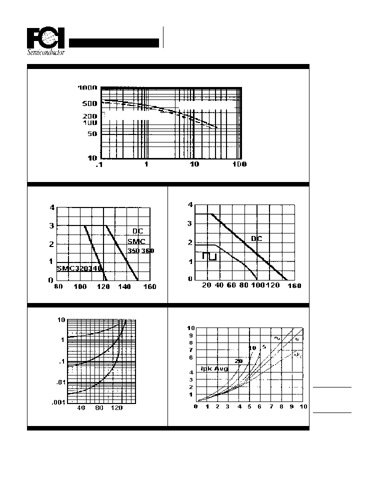
Forward Current Derating Curve
Ambient Temperature (
∞
∞
∞
∞
∞
C)
Junction Capacitance (pF)
Typical Reverse Characteristics
Forward Current Derating Curve
Reverse Current (mA)
Percent of Rated Peak Voltage
Average Power Dissipation
Average Forward Current (A)
Power (W)
Typical Junction Capacitance
Reverse Voltage (V)
Case Temperature (
∞
∞
∞
∞
∞
C)
Average Forward Current (A)
Average Forward Current (A)
SMC320...340
SMC350...360
NOTES: 1. Measured @ 1 MHz and applied reverse voltage of 4.0V.
2. Measured with Pulse Width = 300
µ
S, 2% Duty Cycle.