Preliminary Data Sheet
1.0
FMS2002 ES1
SP3T Reflective pHEMT MMIC Switch
FMS2002 ES1
Description
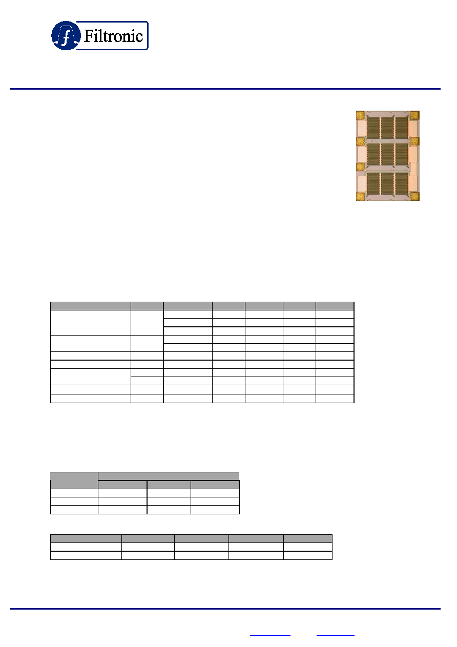
The FMS2002 is a linear high power Single-Pole Three-Throw MMIC
Antenna Switch designed for use in Dual-band handsets GSM900 and
GSM1800/1900 combinations. The switch is designed with one antenna
port that can be routed to any one of the three RF ports
.
Features
∑ Low insertion loss (0.5dB @ 900 MHz)
∑ Operation down to 2V control
∑ 3 control lines. Single positive voltage supply
∑ Low harmonics (Typical -73dBc at Pin=+34.5dBm)
∑ High Isolation (30 dB @ 900 MHz)
∑
Filtronic Advanced GaAs pHEMT Technology
Electrical Characteristics
(at 25C
∞, [V
ctrl
0,+2.7V], 50 Ohm system, under CW )
Parameter
Symbol Condition
Min.
Typ.
Max.
Unit
1
0.45
dB
2
0.55
dB
Insertion Loss
IL
3
0.5
dB
1
35
dB
Isolation ≠
RF ≠ Ant on.
ISO
2
26
dB
S11
S11
1
-25
dB
S11
S11
2
-18
dB
2fo 3
-74
dBc
Harmonics
3fo 3
-73
dBc
Leakage Current - Tx
I
lkTx
3
2.9 mA
Leakage Current ≠ Rx
I
lkRx
3
3.2 mA
Condition
1
Small signal, DC ≠ 1GHz, Vctrl = 2.7V/0V
2
Small signal, 1-2 GHz, Vctrl = 2.7V/0V
3
Input power=34.5dBm, EGSM Tx 880-915MHz, Vctrl=2.7V/0V
GaAs MMIC's are ESD sensitive devices. Special handling precautions are required.
Truth Table
Control Voltage
Operation
Vctrl 1
Vctrl 2
Vctrl 3
RF1-Ant HIGH
0
0
RF2-Ant 0
HIGH 0
RF3-Ant 0
0
HIGH
Control values
Control
Min
Typ.
Max
Unit
High -
2.7
-
V
Low -
0.0
-
V
Preliminary specifications subject to change without notice
Filtronic Compound Semiconductors Ltd, Heighington Lane Business Park, Newton Aycliffe, Co Durham. DL5 6JW.
Contact Details: Tel: +44 (0) 1325 301111 Fax: +44 (0) 1325 306177 Email:
sales@filcs.com
Website:
www.filcs.com

Preliminary Data Sheet
1.0
FMS2002 ES1
Typical Jig Measurements
Harmonic Rejection vs. Control Voltage
Insertion Loss vs. Frequency
-76
-74
-72
-70
-68
-66
-64
-62
-60
1.
7
1.
9
2.
1
2.
3
2.
5
2.
7
2.
9
Control Voltage (V)
Ha
rm
onic
Re
je
c
t
ion (
d
Bc
)
2nd Harmonic
3rd Harmonic
Pin = 34.5 dBm @ 900 MHz
0.3
0.8
1.3
1.8
2
Frequency (GHz)
-1
-0.9
-0.8
-0.7
-0.6
-0.5
-0.4
-0.3
-0.2
-0.1
0
I
n
s
e
rt
i
o
n
L
o
s
s
(d
B
)
Isolation vs. Frequency
0.3
0.8
1.3
1.8
2
Frequency (GHz)
-45
-35
-25
-15
-5
0
I
s
ol
a
t
i
on (
d
B
)
Preliminary specifications subject to change without notice
Filtronic Compound Semiconductors Ltd, Heighington Lane Business Park, Newton Aycliffe, Co Durham. DL5 6JW.
Contact Details: Tel: +44 (0) 1325 301111 Fax: +44 (0) 1325 306177 Email:
sales@filcs.com
Website:
www.filcs.com

Preliminary Data Sheet
1.0
subject to change without notice
miconductors Ltd, Heighington Lane Business Park, Newton Aycliffe, Co Durham. DL5 6JW
+44 (0) 1325 301111 Fax: +44 (0) 1325 306177 Email:
sales@filcs.com
Website:
www.filcs.com
Filtronic Compound Se
.
Contact Details: Tel:
FMS2002 ES1
SP3T Bonding Configuration
Pad Number
Port
Symbol
Connection on Board*
1
RF input port 1
RF 1
RF1
2
RF input port 2
RF 2
RF3
3
DC Control line 2
Vctrl 2
V3
4
RF input port 3
RF 3
RF2
5
DC Control line 1
Vctrl 1
V1
6 Antenna
ANT
ANT
7
DC Control line 3
Vctrl 3
V2
*
RF4, RF 5, V4 and V5 lines are unused.
Bonding Pad Layout
0.00
mm
97 µm (x)
792
µm
(y)
SP3T F1
5
6
593 µm (x)
97 µm (x)
319
µm
(y)
792
µm
(y)
554.75
µm
(y)
48.5
µm
(y)
593 µm (x)
2
1
3
7
4
48.5
µm
(y)
551.5
µm
(y)
97 µm (x)
792
µm
(y)
SP3T F1
SP3T F1
5
6
593 µm (x)
97 µm (x)
319
µm
(y)
792
µm
(y)
554.75
µm
(y)
48.5
µm
(y)
593 µm (x)
2
1
3
2
1
3
7
4
48.5
µm
(y)
551.5
µm
(y)
Preliminary specifications

Preliminary Data Sheet
1.0
Preliminary specifications subject to change without notice
Filtronic Compound Semiconductors Ltd, Heighington Lane Business Park, Newton Aycliffe, Co Durham. DL5 6JW.
Contact Details: Tel: +44 (0) 1325 301111 Fax: +44 (0) 1325 306177 Email:
sales@filcs.com
Website:
www.filcs.com
FMS2002 ES1
Suggested Application Board Layout
0603 100pF surface mount ceramic capacitors
0603 100pF surface mount ceramic capacitors
PCB material: FR4
All transmission lines 50 ohm
90 deg SMA connectors
90 deg SMA connectors
90 deg SMA connector
90 deg SMA connector
0603 100pF surface mount ceramic capacitors
0603 100pF surface mount ceramic capacitors
PCB material: FR4
All transmission lines 50 ohm
90 deg SMA connectors
90 deg SMA connectors
90 deg SMA connector
90 deg SMA connector
Generic SPDT, 3T and 4T Evaluation Board Layout