Document order number: MC33975
Rev 4.0, 08/2005
Freescale Semiconductor
Technical Data
* This document contains certain information on a new product.
Specifications and information herein are subject to change without notice.
© Freescale Semiconductor, Inc., 2005. All rights reserved.
Multiple Switch Detection
Interface with Suppressed
Wake-Up and 32mA Wetting
Current
Freescale offers multiple Switch Detection Interface Devices. The
33975 Multiple Switch Detection Interface with Suppressed Wake-Up
is designed to detect the closing and opening of up to 22 switch
contacts. The switch status, either open or closed, is transferred to the
microprocessor unit (MCU) through a serial peripheral interface (SPI).
The device also features a 22-to-1 analog multiplexer for reading
inputs as analog.
The 33975 device has two modes of operation, Normal and Sleep.
Normal mode allows programming of the device and supplies switch
contacts with pull-up or pull-down current as it monitors switch change
of state. The Sleep mode provides low quiescent current, which makes
the 33975 ideal for automotive and industrial products requiring low
sleep state currents.
Improvements are a programmable interrupt timer for Sleep mode
that can be disabled, switch detection currents of 32 mA and 4.0 mA
for switch-to-ground inputs, and an interrupt bit that can be reset.
Features
∑ Designed to Operate 5.5 V V
PWR
28 V
∑ Switch Input Voltage Range -14 V to V
PWR
∑ Interfaces Directly to Microprocessor Using 3.3 V/5.0 V SPI
Protocol
∑ Selectable Wake-Up on Change of State
∑ Selectable Wetting Current (32 mA or 4.0 mA for switch-to-ground
inputs)
∑ 8 Programmable Inputs (Switches to Battery or Ground)
∑ 14 Switch-to-Ground Inputs
∑ V
PWR
Standby Current 100 µA Typical, V
DD
Standby Current 20 µA Typical
∑ Pb-free 32-terminal suffix EK
Figure 1. 33975 Simplified Application Diagram
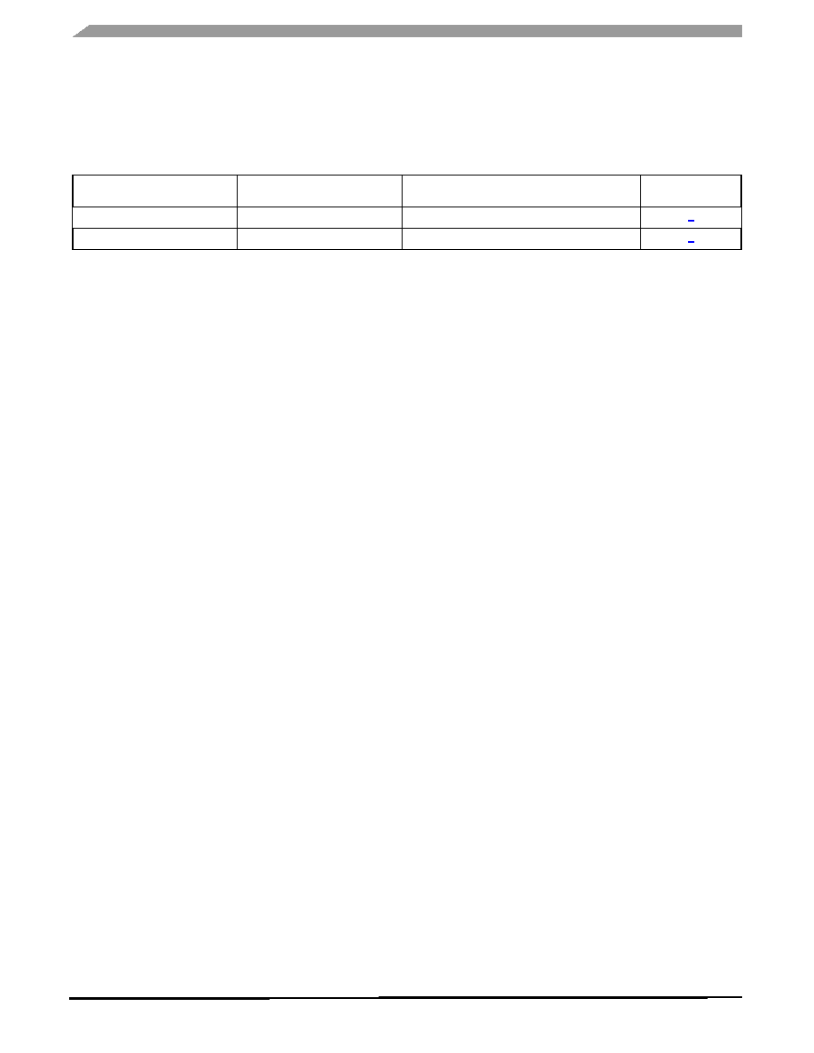
ORDERING INFORMATION
Device
Temperature
Range (T
A
)
Package
MC33975EK/R2
-40∞C to 125∞C
32 SOICW-EP
PC33975AEK/R2
EK Suffix (Pb-Free)
98ARL10543D
32-TERMINAL SOICW EP
33975
33975A
MULTIPLE SWITCH
DETECTION INTERFACE WITH
SUPPRESSED WAKE-UP
33975
VBAT
VBAT
SP0
SP1
SP7
SG0
SG1
SG12
SG13
VPWR
VDD
AMUX
WAKE
GND
INT
SO
SI
SCLK
CS
MCU
AN0
INT
MISO
MOSI
SCLK
CS
Power Supply
LVI
Watchdog
Reset
Enable
VBAT
VDD
VDD
Analog Integrated Circuit Device Data
4
Freescale Semiconductor
33975
TERMINAL CONNECTIONS
TERMINAL CONNECTIONS
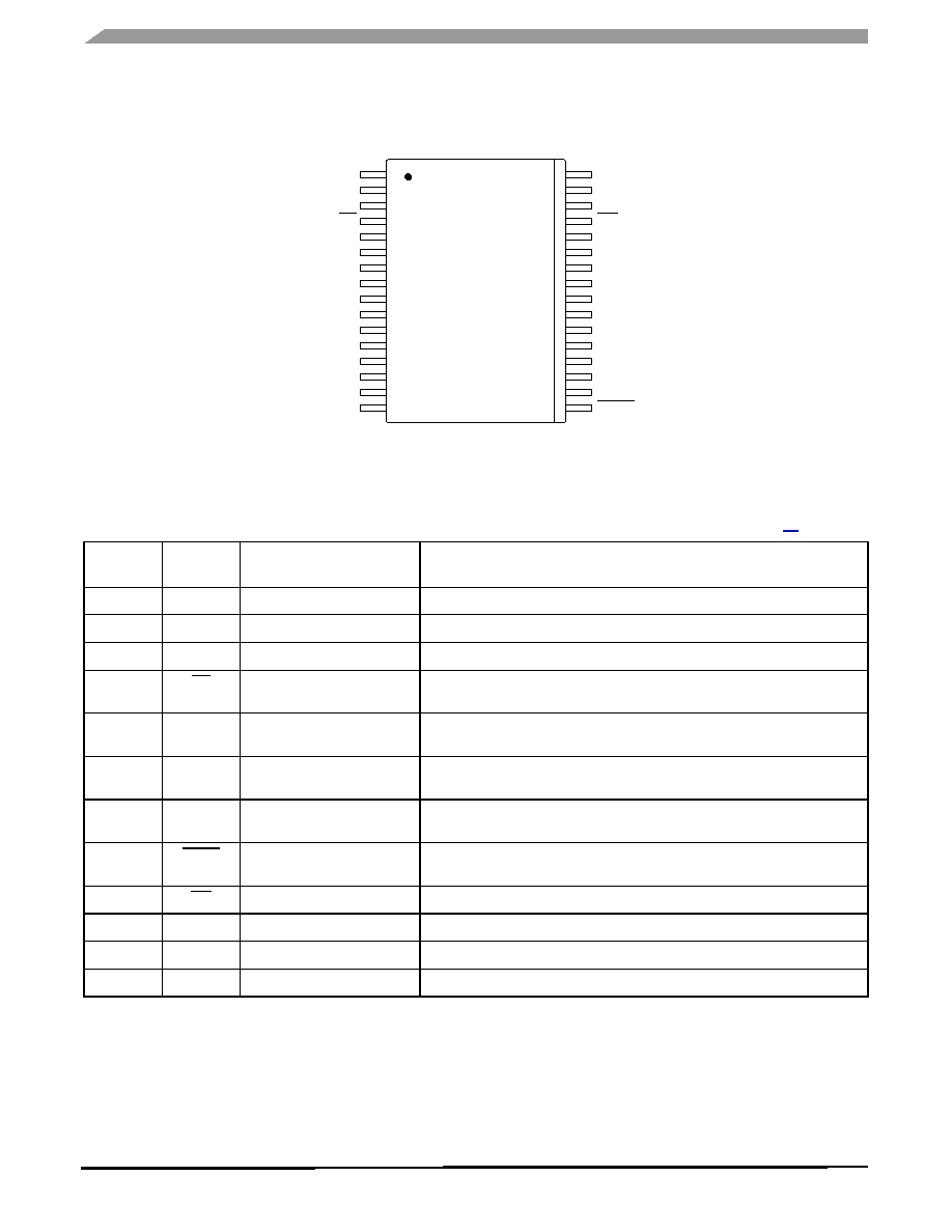
Figure 3. 33975 Terminal Connections
Table 2. Terminal Definitions
A functional description of each terminal can be found in the Functional Terminal Description section on page
11
.
Terminal
Terminal
Name
Formal Name
Description
1
GND
Ground
Ground for logic, analog, and switch-to-battery inputs.
2
SI
SPI Slave In
SPI control data input terminal from MCU to 33975.
3
SCLK
Serial Clock
SPI control clock input terminal.
4
CS
Chip Select
SPI control chip select input terminal from MCU to 33975. Logic [0] allows data
to be transferred in.
5≠8
25≠28
SPn
Programmable Switches 0≠3
Programmable Switches 4≠7
Programmable switch-to-battery or switch-to-ground input terminals.
9≠15,
18≠24
SGn
Switch-to-Ground Inputs 0≠6
Switch-to-Ground Inputs 13≠7
Switch-to-ground input terminals.
16
VPWR
Battery Input
Battery supply input terminal. This terminal requires external reverse battery
protection.
17
WAKE
Wake-Up
Open drain wake-up output is designed to control a power supply enable
terminal.
29
INT
Interrupt
Open-drain output to MCU is used to indicate input switch change of state.
30
AMUX
Analog Multiplex Output
Analog multiplex output.
31
VDD
Voltage Drain Supply
3.3/5.0 V supply sets SPI communication level for SO driver.
32
SO
SPI Slave Out
Provides digital data from 33975 to MCU.
SO
1
SP7
SP6
SP5
SP4
SG7
SG8
SG9
SG10
SG11
SG13
WAKE
SG12
INT
VDD
AMUX
GND
SP0
SP1
SP2
SP3
SG0
SG1
SG2
SG3
SG4
SG6
VPWR
SG5
CS
SI
SCLK
8
9
10
11
12
13
14
15
16
3
4
5
6
7
2
32
25
24
23
22
21
20
19
18
17
30
29
28
27
26
31
Analog Integrated Circuit Device Data
Freescale Semiconductor
5
33975
MAXIMUM RATINGS
MAXIMUM RATINGS
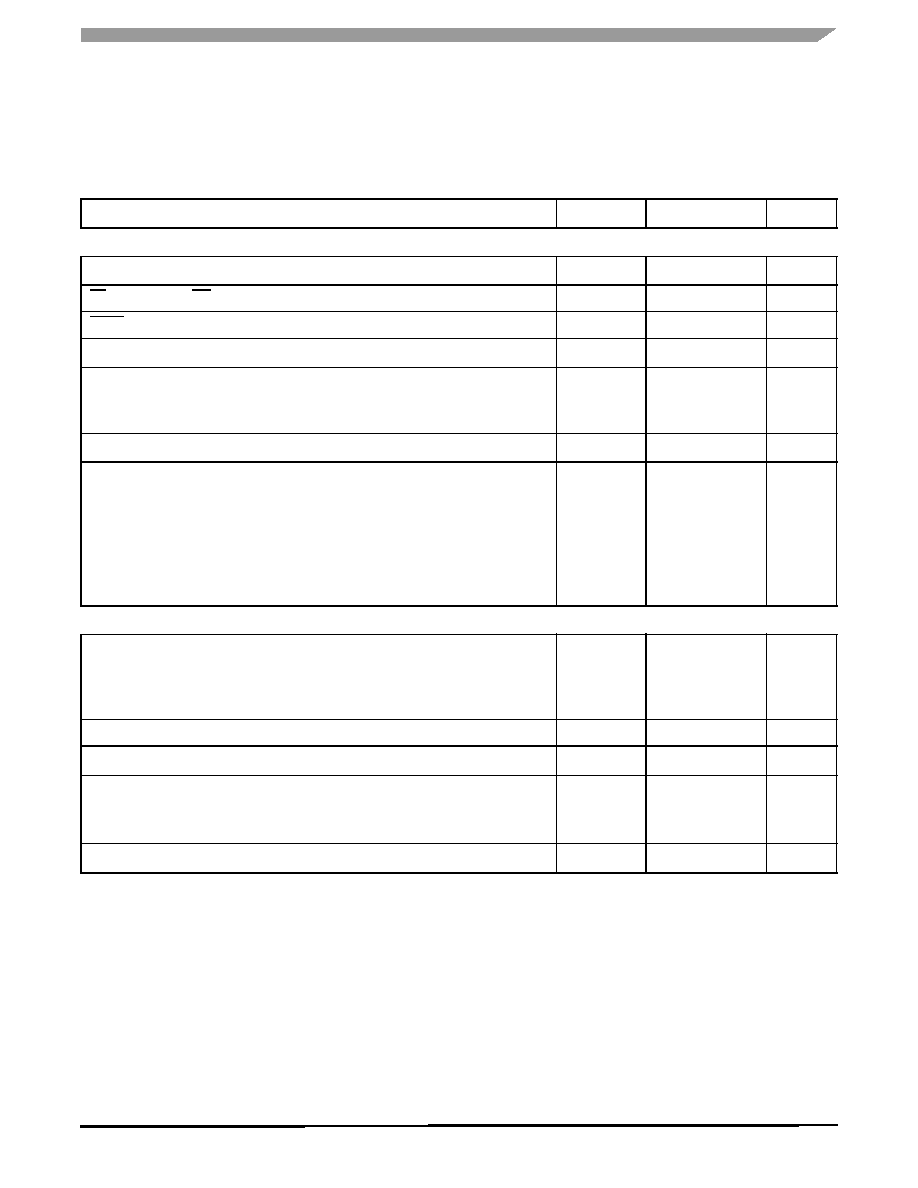
Table 3. Maximum Ratings
All voltages are with respect to ground unless otherwise noted. Exceeding these limits may cause malfunction or permanent
damage to the device.
Rating
Symbol
Value
Unit
ELECTRICAL RATINGS
V
DD
Supply Voltage
≠
-0.3 to 7.0
V
DC
CS,
SI, SO, SCLK, INT, AMUX
≠
-0.3 to 7.0
V
DC
WAKE
≠
-0.3 to 40
V
DC
V
PWR
Supply Voltage
≠
-0.3 to 50
V
DC
Switch Input Voltage Range
MC33975
PC339775A
≠
-14 to 38
-14 to 40
V
DC
Frequency of SPI Operation (V
DD
= 5.0 V)
≠
6.0
MHz
ESD Voltage
(1)
Human Body Model
(2)
Applies to all non-input terminals
Machine Model
Charge Device Model
Corner Terminals
Interior Terminals
V
ESD
±4000
±2500
±200
750
500
V
THERMAL RATINGS
Operating Temperature
Ambient
Junction
Case
T
A
T
J
T
C
-40 to 125
-40 to 150
-40 to 125
∞
C
Storage Temperature
T
STG
-55 to 150
∞
C
Power Dissipation
(3)
P
D
1.7
W
Thermal Resistance
Junction to Ambient
Between the Die and the Exposed Die Pad
(4)
R
JA
R
JC
71
1.2
∞
C/W
Peak Package Reflow Temperature During Solder Mounting
(5)
T
SOLDER
245
∞
C
Notes
1.
ESD testing is performed in accordance with the Human Body Model (C
ZAP
= 100 pF, R
ZAP
= 1500 ), the Machine Model (C
ZAP
= 200
pF, R
ZAP
= 0 ), and the Charge Device Model.
2.
All Programmable Switches (SP) and Switch-to-Ground (SG) input terminals when tested individually.
3.
Maximum power dissipation at T
J
=150
∞
C junction temperature with no heatsink used.
4.
Thermal resistance between the die and the exposed die pad.
5.
Terminal soldering temperature limit is for 10 seconds maximum duration. Not designed for immersion soldering. Exceeding these limits
may cause malfunction or permanent damage to the device.