 | –≠–ª–µ–∫—Ç—Ä–æ–Ω–Ω—ã–π –∫–æ–º–ø–æ–Ω–µ–Ω—Ç: AS-48W-K | –°–∫–∞—á–∞—Ç—å:  PDF PDF  ZIP ZIP |

s
FEATURES
q
Flat type relay for surface mounting
q
Super small and light weight
--Height: 6.5 mm
--Weight: approximately 1.5 g
q
UL, CSA recognized
q
Conforms to FCC Part 68
--Surge strength 1,500 V
q
High sensitivity and low power consumption
q
High reliability--bifurcated contacts
q
DIL pitch terminals
q
Plastic sealed type
(a)
Series Name
AS : AS Series
(b)
Operation Function
Nil : Standard type
L
: Latching type
(c)
Number of Coil
Nil : Single winding type
D : Double winding type
(d)
Nominal Voltage
Refer to the COIL DATA CHART
(e)
Contact
W : Bifurcated type
(f )
Enclosure
K : Plastic sealed type
(g)
Packing Orientation
B : Standard type
(h)
Packing Quantity
05 : 500 pieces
Note: Actual marking omits the hyphen (-) of (*) and "-B05"
s
ORDERING INFORMATION
AS
L
≠
D
12 W
≠
K
≠
B
05
[Example]
(a)
(b) (*) (c) (d) (e) (*) (f ) (*) (g) (h)
AS SERIES
MINIATURE RELAY
2 POLES--1 to 2 A
(FOR SIGNAL SWITCHING)
NOT FOR NEW
DESIGNS
2
AS SERIES
NOT FOR NEW
DESIGNS
Nominal voltage
Contact rating
0.5 A
125 VAC
1.5 to 48 VDC
2 A 30 VDC
resistive
0.3 A 110 VDC
s
SAFETY STANDARD AND FILE NUMBERS
UL478, 508 (File No. E45026)
C22.2 No. 14 (File No. LR35579)
Only UL/CSA approval markings are marked on the cover.
s
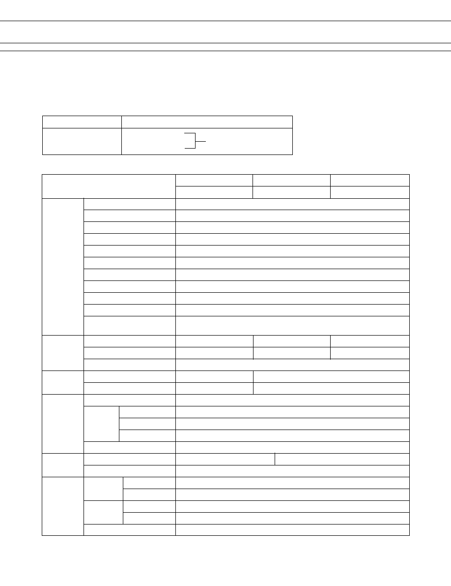
SPECIFICATIONS
Standard Type
Single Winding Latching Type Double Winding Latching Type
Item
AS-( ) W-K
ASL-( ) W-K
ASL-D ( ) W-K
Contact
Arrangement
2 Form C (DPDT)
Material
Gold overlay silver alloy
Style
Bifurcated
Resistance (initial)
Maximum 50 m
(at 1 A 6 VDC)
Rating (resistive)
0.5 A 125 VAC or 1 A 30 VDC
Maximum Carrying Current
2 A
Maximum Switching Power
62.5 AV, 30 W
Maximum Switching Voltage
250 VAC, 220 VDC
Maximum Switching Current
2 A
Minimum Switching Load*
1
0.01 mA 10 mVDC
Capacitance
Approximately 0.5 pF (between open contacts, adjacent contacts)
(at 1 kHz)
Approximately 1.0 pF (between coil and contacts)
Coil
Nominal Power (at 20
∞
C)
0.14 to 0.3 W 0.1 to 0.15 W
0.20 to 0.3 W
Operate Power (at 20
∞
C)
0.08 to 0.17 W 0.06 to 0.085 W 0.11 5 to 0.17 W
Operating Temperature
≠40
∞
C to +85
∞
C (no frost) (refer to the CHARACTERISTIC DATA)
Time Value
Operate (at nominal voltage)
Maximum 6 ms Maximum 6 ms (set)
Release (at nominal voltage)
Maximum 4 ms Maximum 6 ms (reset)
Insulation
Resistance (at 500 VDC)
Minimum 1,000 M
between open contacts
750 VAC 1 minute
Dielectric
between adjacent contacts
1,000 VAC 1 minute
Strength
between coil and contacts
1,000 VAC 1 minute
Surge Strength
1,500 V (at 10
◊
160
µ
s) (between coil and contacts)
Life
Mechanical
1
◊
10
8
operations minimum 1
◊
10
7
operations minimum
Electrical
2
◊
10
5
ops. min. (0.5 A 125 VAC), 5
◊
10
5
ops. min. (1 A 30 VDC)
Other
Vibration Misoperation
10 to 55 Hz (double amplitude of 3.3 mm)
Resistance Endurance
10 to 55 Hz (double amplitude of 5.0 mm)
Shock Misoperation
500 m/s
2
(11
±
1 ms)
Resistance Endurance
1,000 m/s
2
( 6
±
1 ms)
Weight
Approximately 1.5 g
*
1
Minimum switching loads mentioned above are reference values. Please perform the confirmation test with the actual
load before production since reference values may vary according to switching frequencies, environmental conditions
and expected reliability levels.

3
AS SERIES
NOT FOR NEW
DESIGNS
MODEL
Nominal
Coil resistance
Must operate
Must release
Nominal
voltage
(
±
10%)
voltage*
1
voltage*
1
power
AS-1.5 W-K
1.5 VDC
16.1
+1.13 VDC
+0.15 VDC
140 mW
AS- 3 W-K
3 VDC
64.3
+2.25 VDC
+0.3 VDC
140 mW
AS-4.5 W-K
4.5 VDC
145
+3.38 VDC
+0.45 VDC
140 mW
AS- 5 W-K
5 VDC
178
+3.75 VDC
+0.5 VDC
140 mW
AS- 6 W-K
6 VDC
257
+4.5 VDC
+0.6 VDC
140 mW
AS- 9 W-K
9 VDC
579
+6.75 VDC
+0.9 VDC
140 mW
AS- 12 W-K
12 VDC
1,028
+9.0 VDC
+1.2 VDC
140 mW
AS- 18 W-K
18 VDC
1,620
+13.5 VDC
+1.8 VDC
200 mW
AS- 24 W-K
24 VDC
2,880
+18.0 VDC
+2.4 VDC
200 mW
AS- 48 W-K
48 VDC
7,680
+36.0 VDC
+4.8 VDC
300 mW
s
COIL DATA CHART
Standard T
ype
Note: *
1
Specified values are subject to pulse wave voltage.
All values in the table are measured at 20
∞
C.
Nominal
Coil resistance
Set
Reset
Nominal
MODEL
voltage
(
±
10%)
voltage*
1
voltage*
1
power
ASL-1.5 W-K
1.5 VDC
22.5
+1.13 VDC
-1.13 VDC
100 mW
ASL- 3 W-K
3 VDC
90
+2.25 VDC
-2.25 VDC
100 mW
ASL-4.5 W-K
4.5 VDC
203
+3.38 VDC
-3.38 VDC
100 mW
ASL- 5 W-K
5 VDC
250
+3.75 VDC
-3.75 VDC
100 mW
ASL- 6 W-K
6 VDC
360
+4.5 VDC
-4.5 VDC
100 mW
ASL- 9 W-K
9 VDC
810
+6.75 VDC
-6.75 VDC
100 mW
ASL- 12 W-K
12 VDC
1,440
+9.0 VDC
-9.0 VDC
100 mW
ASL- 18 W-K
18 VDC
2,160
+13.5 VDC
-13.5 VDC
150 mW
ASL- 24 W-K
24 VDC
3,840
+18.0 VDC
-18.0 VDC
150 mW
ASL-D1.5 W-K
1.5 VDC
P 11.25
+1.13 VDC
200 mW
S 11.25
+1.13 VDC
ASL-D 3 W-K
3 VDC
P 45
+2.25 VDC
200 mW
S 45
+2.25 VDC
ASL-D4.5 W-K
4.5 VDC
P 101
+3.38 VDC
200 mW
S 101
+3.38 VDC
ASL-D 5 W-K
5 VDC
P 125
+3.75 VDC
200 mW
S 125
+3.75 VDC
ASL-D 6 W-K
6 VDC
P 180
+4.5 VDC
200 mW
S 180
+4.5 VDC
ASL-D 9 W-K
9 VDC
P 405
+6.75 VDC
200 mW
S 405
+6.75 VDC
ASL-D 12 W-K
12 VDC
P 720
+9.0 VDC
200 mW
S 720
+9.0 VDC
ASL-D 18 W-K
18 VDC
P 1,080
+13.5 VDC
300 mW
S 1,080
+13.5 VDC
ASL-D 24 W-K
24 VDC
P 1,920
+18.0 VDC
300 mW
S 1,920
+18.0 VDC
Single W
inding Latching
T
ype
Double Winding Latching
T
ype
P: Primary coil S: Secondary coil
Note: *
1
Specified values are subject to pulse wave voltage.
All values in the table are measured at 20
∞
C.
4
AS SERIES
NOT FOR NEW
DESIGNS
s
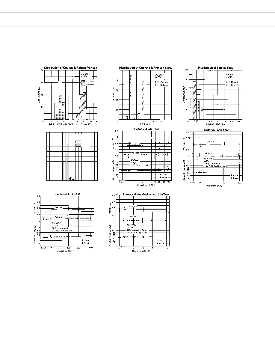
REFERENCE DATA
s
CHARACTERISTIC DATA
Please see A relays.
100
80
60
40
20
0
10
20
30
40
50
60
70
80
AS-5W-K
n=100
Make
Break
P
z
P
~
Contact Res istance (m
)
Distribution
(%)
Distribution of Contact Resistance

5
AS SERIES
NOT FOR NEW
DESIGNS
s
DIMENSIONS
q
Dimensions
q
Schematics
(TOP VIEW)
q
PC board mounting
pad layout
(TOP VIEW)
AS, ASL type (Non-latching type, single winding latching type)
ASL-D type (Double winding latching type)
s
RECOMMENDED SOLDERING CONDITIONS
(TEMPERATURE PROFILE)
Note:
1. Temperature profiles show the temperature of the PC board sur-
face.
2. Please perform soldering test with your actual PC board before
mass production, since the temperatures of PC board surfaces
vary according to the size of PC board, status of parts mounting
and heating method.
Unit: mm
6
AS SERIES
NOT FOR NEW
DESIGNS
s
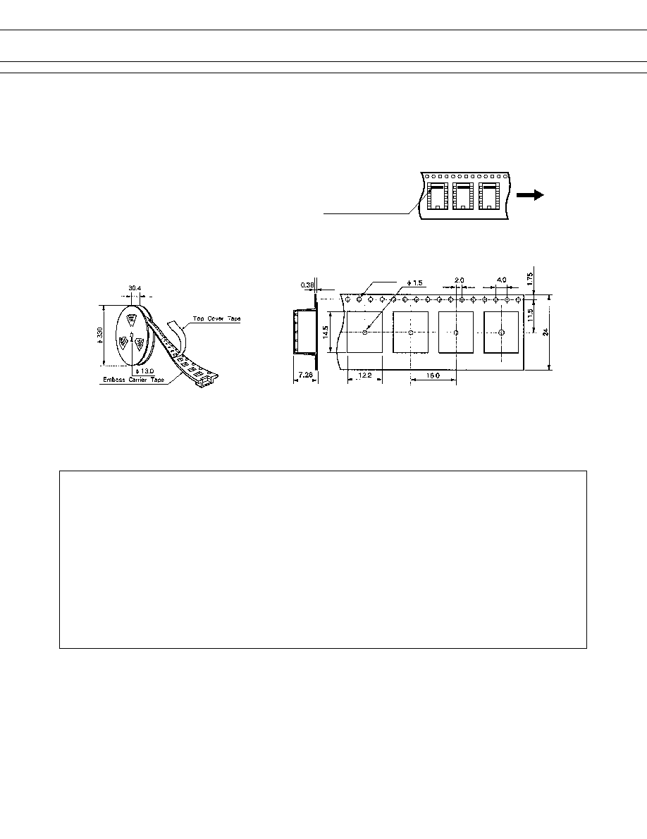
PACKING
(1) PACKING METHOD (ONLY TAPE PACKING IS AVAILABLE)
∑ Taping standards : JIS C 0806 and
RC - 1009B (EIAJ)
∑ Tape type : TB2416 or TE2416
∑ Reel type : R24D
∑ Quantity of 1 reel : 500 pieces
∑ Packing orientation code : B
Feeding
Orientation mark side
(2) DIMENSIONS (in mm)
∑ REEL DIMENSIONS
∑ TAPE DIMENSIONS
Note:
Relays are sold in packs of 500 pieces, please order
500 pieces as one unit.
¯ 1.55
© 2002 Fujitsu Components America, Inc. All company and product names are trademarks or registered trademarks
of their respective owners. Rev. 03/2002
Japan
Fujitsu Component Limited
Gotanda-Chuo Building
3-5, Higashigotanda 2-chome, Shinagawa-ku
Tokyo 141, Japan
Tel: (81-3) 5449-7010
Fax: (81-3) 5449-2626
Email: promothq@ft.ed.fujitsu.com
Web: www.fcl.fujitsu.com
North and South America
Fujitsu Components America, Inc.
250 E. Caribbean Drive
Sunnyvale, CA 94089 U.S.A.
Tel: (1-408) 745-4900
Fax: (1-408) 745-4970
Email: marcom@fcai.fujitsu.com
Web: www.fcai.fujitsu.com
Europe
Fujitsu Components Europe B.V.
Diamantlaan 25
2132 WV Hoofddorp
Netherlands
Tel: (31-23) 5560910
Fax: (31-23) 5560950
Email: info@fceu.fujitsu.com
Web: www.fceu.fujitsu.com
Asia Pacific
Fujitsu Components Asia Ltd.
102E Pasir Panjang Road
#04-01 Citilink Warehouse Complex
Singapore 118529
Tel: (65) 375-8560
Fax: (65) 273-3021
Email: fcal@fcal.fujitsu.com
www.fcal.fujitsu.com
Fujitsu Components
International
Headquarter
Offices