DS04-23121-1E
FUJITSU SEMICONDUCTOR
DATA SHEET
ASSP
Mobile Communication Systems
SAW Dual Filter
(700 to 2000 MHz)
G5/G6 Series (L2/D2 type)
s
DESCRIPTION
As the market for handheld phones continues to increase, so has demand for smaller size, lighter weight and
lower cost. Dual band phones, such as GSM + PCN and AMPS + PCS, are rising in popularity. To support these
requests, Fujitsu has developed a new series of SAW dual filter (G5/G6 series) incorporating two SAW filters in
one package.
For example, Fujitsu can offer a GSM Rx filter and a PCN Rx filter of combination in small 3.8 mm sq. package.
The G5/G6 series of SAW dual filter applies to the 700 to 2000 MHz, frequency range, and are available in two
package types: 2 input/2 output type or 1 input/2 output (2 input/1 output).
s
FEATURES
∑ Two functions are incorporated in one package
(Useful for multi-band phone and multi-mode phone)
∑ Ultra compact and light package (3.8 mm sq. or 3.0 mm sq.)
∑ 50
of input/output impedance
∑ Low insertion loss
∑ 2 in/2 out and 1 in/2 out (2 in/1 out) of package types are available
s
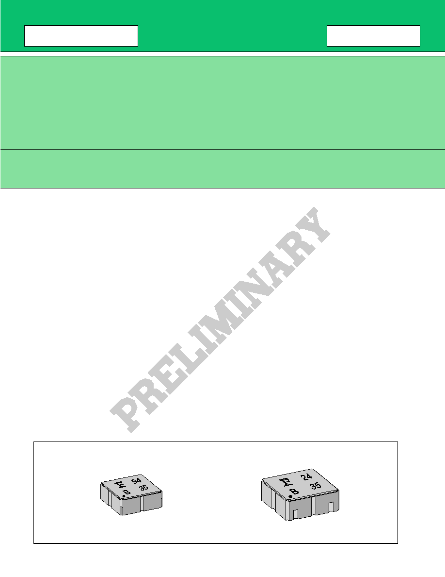
PACKAGES
To Top / Lineup / Index

3
G5/G6 Series
s
ABSOLUTE MAXIMUM RATINGS
WARNING: Piezoelectric devices can be permanently damaged by application of stress (voltage, current,
temperature, etc.) in excess of absolute maximum ratings. Do not exceed these ratings.
s
RECOMMENDED OPERATING CONDITIONS
WARNING: The recommended operating conditions are required in order to ensure the normal operation of the
piezoelectric device. All of the device's electrical characteristics are warranted when the device is
operated within these ranges.
Always use piezoelectric devices within their recommended operating condition ranges. Operation
outside this range may adversely affect reliability and could result in device failure.
No warranty is made with respect to uses, operating conditions, or combinations not represented on
the data sheet. Users considering application outside the listed conditions are advised to contact their
FUJITSU representatives beforehand.
Item
Symbol
Rating
Unit
Min.
Max.
Operating temperature
Ta
≠30
+85
∞
C
Storage temperature
Tstg
≠40
+100
∞
C
Maximum DC voltage
DC
≠5
+5
V
Maximum input power
P
IN
Depends on each design.
See "
s
ELECTRICAL CHARACTERISTICS".
Item
Symbol
Value
Unit
Min.
Max.
Operating temperature
Ta
≠30
+85
∞
C
To Top / Lineup / Index

4
G5/G6 Series
s
STANDARD FREQUENCIES
No.
Part number
System
Frequency (MHz)
Part
symbol
Input/
Output
Remarks
1
FAR-G5CN-942M50-D294
PDC800 Tx
893 to 898 MHz
94
1 in/
2 out
925 to 960 MHz
2
FAR-G5CN-877M50-D292
PDC800 Rx
810 to 843 MHz
92
1 in/
2 out
870 to 885 MHz
3
FAR-G6CH-1G8800-L214
AMPS Tx
(TDMA, CDMA)
PCS Tx
824 to 849 MHz
14
2 in/
2 out
1850 to 1910 MHz
4
FAR-G6CH-1G9600-L215
AMPS Rx
(TDMA, CDMA)
PCS Rx
869 to 894 MHz
15
2 in/
2 out
1930 to 1990 MHz
5
FAR-G6CH-1G7475-L216
GSM Tx
890 to 915 MHz
16
2 in/
2 out
PCN Tx
1710 to 1785 MHz
6
FAR-G6CH-1G8425-L217
GSM Rx
935 to 960 MHz
17
2 in/
2 out
PCN Rx
1805 to 1880 MHz
7
FAR-G6CH-1G8425-L224
EGSM Rx
925 to 960 MHz
24
2 in/
2 out
PCN Rx
1805 to 1880 MHz
8
FAR-G6CH-1G9600-L219
PCN Rx
1805 to 1880 MHz
19
2 in/
2 out
PCS Rx
1930 to 1990 MHz
9
FAR-G6CH-1G8950-L210D
PCS Tx
Split
Low
1850 to 1880 MHz
10
2 in/
2 out
High
1880 to 1910 MHz
10
FAR-G6CH-1G9750-L230
PCS Rx
Split
Low
1930 to 1960 MHz
30
2 in/
2 out
High
1960 to 1990 MHz
To Top / Lineup / Index

5
G5/G6 Series
s
ELECTRICAL CHARACTERISTICS
1. PDC800 (Tx) 1 in/2 out
Part number: FAR-G5CN-942M50-D294
(Ta = ≠30 to +85
∞
C)
Item
Symbol
Condition
Value
Unit
Remarks
Min.
Typ.
Max.
Insertion Loss
IL
893 to 898 MHz
--
--
4.0
dB
≠30 to +20
∞
C
--
2.5
3.2
dB
+20 to +85
∞
C
Inband Ripple
--
893 to 898 MHz
--
1.7
dB
≠30 to +20
∞
C
--
0.2
1.0
dB
+20 to +85
∞
C
Absolute
Attenuation
--
500 to 570 MHz
35
42
--
dB
--
570 to 700 MHz
30
33
--
dB
--
700 to 810 MHz
22
26
--
dB
--
810 to 875 MHz
15
20
--
dB
--
875 to 885 MHz
10
15
--
dB
≠30 to +30
∞
C
7
--
--
dB
+30 to +85
∞
C
--
925 to 1000 MHz
14
17
--
dB
--
1000 to 1200 MHz
25
29
--
dB
Inband VSWR
--
893 to 898 MHz
--
1.9
3.0
--
Max. Input Power
Pin
893 to 898 MHz
--
--
15
dBm
Insertion Loss
IL
925 to 960 MHz
--
3.2
4.2
dB
Inband Ripple
--
925 to 960 MHz
--
1.7
2.7
dB
Absolute
Attenuation
--
500 to 630 MHz
40
45
--
dB
--
630 to 710 MHz
35
40
--
dB
--
710 to 740 MHz
30
38
--
dB
--
740 to 800 MHz
28
33
--
dB
--
800 to 885 MHz
23
28
--
dB
--
1000 to 1050 MHz
15
18
--
dB
--
1050 to 1200 MHz
28
32
--
dB
Inband VSWR
--
925 to 960 MHz
--
1.9
3.0
--
Max. Input Power
Pin
925 to 960 MHz
--
--
15
dBm
Filter 1
Filter 2
To Top / Lineup / Index
