 | –≠–ª–µ–∫—Ç—Ä–æ–Ω–Ω—ã–π –∫–æ–º–ø–æ–Ω–µ–Ω—Ç: VB-60M | –°–∫–∞—á–∞—Ç—å:  PDF PDF  ZIP ZIP |

s
ORDERING INFORMATION
VB
≠
12
S
M
B
U
≠
5
[Example]
(a) (*) (b)
(c) (d) (e) (f) (*) (g)
s
FEATURES
q
UL, CSA, VDE, SEV, SEMKO, FIMKO, IMQ recognized
TV-3 rated
q
Working class: C
q
UL class B (130
∞
C) insulation
q
Type of service: continuous duty
q
Heavy duty miniature slim type power relay
q
High isolation in small package
--Insulation distance: 8 mm
--Dielectric strength: 5,000 VAC (between coil and con-
tacts)
--Surge strength: 10,000 V
q
Standard and high sensitivity types available
q
Flux free type and plastic sealed type available
(a)
Series Name
VB: VB Series
(b)
Nominal Voltage
Refer to the COIL DATA CHART
(c)
Coil Type
Nil : Standard type
S : High sensitive type (non TV-rating)
(d)
Contact Arrangement
M : 2 form A (DPST-NO)
T : 2 form C (DPDT)
B : Flux free type
(e)
Enclosure
C : Plastic sealed type (with tape)
K : Plastic sealed type
(f)
Standard
Nil : TV-rating
U : General (non TV-rating)
Nil : Silver cadmium oxide (TV-3 rating)
(g)
Contact Material
5 : Silver cadmium oxide (non TV-rating)
Nil : Gold overlay silver-nickel (non TV-rating)
E : Silver-nickel (non TV-rating)
Actual marking omits the hyphen (≠) of (*)
VB SERIES
POWER RELAY
2 POLE--5 A
(MEDIUM LOAD CONTROL)
1
2
VB SERIES
Type
Nominal voltage
Contact rating
TV-3
120 VAC
TV-Rating
VB-( ) M
3 to 100 VDC
1/6HP
120 VAC/240 VAC
5 A
24 VDC/240 VAC resistive
1.9A 250VAC indcutive (PF=0.4)
Pilot duty C 150
VB-( ) ( ) U-( )
1/6HP
120 VAC/240 VAC
Standard
VB-( ) S ( ) U-( )
3 to 100 VDC
5 A
24 VDC/240 VAC resistive
1.9A 250VAC inductive (PF=0.4)
Pilot duty C 150
s
SAFETY STANDARD AND FILE NUMBERS
UL508, 873 (File No. E56140, E108658)
C 22.2 No. 1, No. 14 (File No. LR35579)
VDE0435, 0630, 0631, 0700, 0860 (File No. 11039-4940-1009)
Please note that UL/CSA ratings may differ from the standard ratings. Please request when the approval markings
are required on the cover and/or when a relay recognized by VDE, SEV, SEMKO, FIMKO, IMQ is required.

3
VB SERIES
s
SPECIFICATIONS
Item
TV-3 Rating
Standard Type
VB-( ) M
VB-( ) U-5
VB-( ) U
VB-( )-E
Contact
Arrangement
2 form A (DPST-NO)
2 form A (DPST-NO) or 2 form C (DPDT)
Material
Silver-cadmium oxide
Gold overlay
silver-nickel
(non gold overlay
only VB-E)
Style
Single
Resistance (initial)
Maximum 200 m
Maximum 100 m
(at 1 A 6 VDC)
Rating (resistive)
5 A 240 VAC/24 VDC
Maximum Carrying Current
7 A
Maximum Switching Power
1,200 VA, 120 W
Maximum Switching Voltage
380 VAC, 150 VDC
Maximum Switching Current
5 A
Minimum Switching Load *
1
100 mA 5 VDC (VB-M, 5, E) 10 mA 5 VDC (VB-)
Maximum Inrush Current
51 A 120 VAC (at lamp load) --
Coil
Nominal Power (at 20
∞
C)
Standard type: 0.70 to 0.75 W, high sensitivity type: 0.53 W
Operate Power (at 20
∞
C)
Standard type: 0.35 to 0.37 W, high sensitivity type: 0.26 W
Operating Temperature
Standard type: ≠40
∞
C to +65
∞
C, high sensitivity type: ≠40
∞
C to +75
∞
C (no frost)
Time Value
Operate (at nominal voltage)
Maximum 15 ms
Release (at nominal voltage)
Maximum 10 ms
Insulation
Resistance (at 500 VDC)
Minimum 1,000 M
Dielectric
between open contacts
1,000 VAC 1 minute (3000 VAC between adjacent contacts)
Strength
between coil and contacts*
2
5,000 VAC 1 minute
Surge Strength*
3
10,000 V at(1.2
◊
50
µ
s)
Life
Mechanical
2
◊
10
7
operations minimum
Electrical
1
◊
10
5
operations minimum at rated load
5
◊
10
4
operations 3
◊
10
4
operations minimum
minimum at motor load at motor load
(1/8HP 120 VAC) (1/8HP 120 VAC)
5
◊
10
4
operations
--
minimum at lamp load
Other
Vibration
Misoperation
10 to 55 Hz (double amplitude of 1.5 mm)
Resistance
Endurance
10 to 55 Hz (double amplitude of 1.5 mm)
Shock
Misoperation
100 m/s
2
(11
±
1
ms)
Resistance
Endurance
1,000 m/s
2
(6
±
1
ms)
Weight
Approximately 17 g
*
1
Minimum switching loads mentioned above are reference values. Please perform the confirmation test with the actual load
before production since reference values may vary according to switching frequencies, environmental conditions and
expected reliability levels.
*
2
IMQ
*
3
IMQ
2
0

4
VB SERIES
s
COIL DATA CHART
MODEL
Nominal
Coil resistance Must operate Must release
Nominal
TV-3 Rating
Standard
voltage
(10%)
voltage
voltage
power
VB- 3M ( )
VB- 3 ( ) ( ) U-( )
3 V DC
12.5
2.1 VDC
0.3 VDC
0.72 W
VB- 5M ( )
VB- 5 ( ) ( ) U-( )
5 V DC
36
3.5 VDC
0.5 VDC
0.70 W
VB- 6M ( )
VB- 6 ( ) ( ) U-( )
6 V DC
50
4.2 VDC
0.6 VDC
0.72 W
VB- 9M ( )
VB- 9 ( ) ( ) U-( )
9 V DC
115
6.3 VDC
0.9 VDC
0.70 W
VB- 12M ( )
VB- 12 ( ) ( ) U-( )
12 V DC
200
8.4 VDC
1.2 VDC
0.72 W
VB- 14M ( )
VB- 14 ( ) ( ) U-( )
14 V DC
280
9.8 VDC
1.4 VDC
0.70 W
VB- 18M ( )
VB- 18 ( ) ( ) U-( )
18 V DC
460
12.6 VDC
1.8 VDC
0.70 W
VB- 24M ( )
VB- 24 ( ) ( ) U-( )
24 V DC
820
16.8 VDC
2.4 VDC
0.70 W
VB- 36M ( )
VB- 36 ( ) ( ) U-( )
36 V DC
1,850
25.2 VDC
3.6 VDC
0.70 W
VB- 48M ( )
VB- 48 ( ) ( ) U-( )
48 V DC
3,300
33.6 VDC
4.8 VDC
0.70 W
VB- 60M ( )
VB- 60 ( ) ( ) U-( )
60 V DC
5,100
42.0 VDC
6.0 VDC
0.70 W
VB-100M ( )
VB-100 ( ) ( ) U-( )
100 V DC
13,400
70.0 VDC
10.0 VDC
0.75 W
VB- 3S( ) ( ) U-( )
3 V DC
17
2.1 VDC
0.3 VDC
0.53 W
VB- 5S( ) ( ) U-( )
5 V DC
47
3.5 VDC
0.5 VDC
0.53 W
VB- 6S( ) ( ) U-( )
6 V DC
68
4.2 VDC
0.6 VDC
0.53 W
VB- 9S( ) ( ) U-( )
9 V DC
155
6.3 VDC
0.9 VDC
0.53 W
VB-12S( ) ( ) U-( )
12 V DC
270
8.4 VDC
1.2 VDC
0.53 W
VB-14S( ) ( ) U-( )
14 V DC
370
9.8 VDC
1.4 VDC
0.53 W
VB-18S( ) ( ) U-( )
18 V DC
610
12.6 VDC
1.8 VDC
0.53 W
VB-24S( ) ( ) U-( )
24 V DC
1,100
16.8 VDC
2.4 VDC
0.53 W
VB-36S( ) ( ) U-( )
36 V DC
2,450
25.2 VDC
3.6 VDC
0.53 W
VB-48S( ) ( ) U-( )
48 V DC
4,400
33.6 VDC
4.8 VDC
0.53 W
VB-60S( ) ( ) U-( )
60 V DC
6,800
42.0 VDC
6.0 VDC
0.53 W
VB-100S( ) ( ) U-( )
100 V DC
18,860
70.0 VDC
10.0 VDC
0.53 W
Standard T
ype
High Sensitivity
T
ype
s
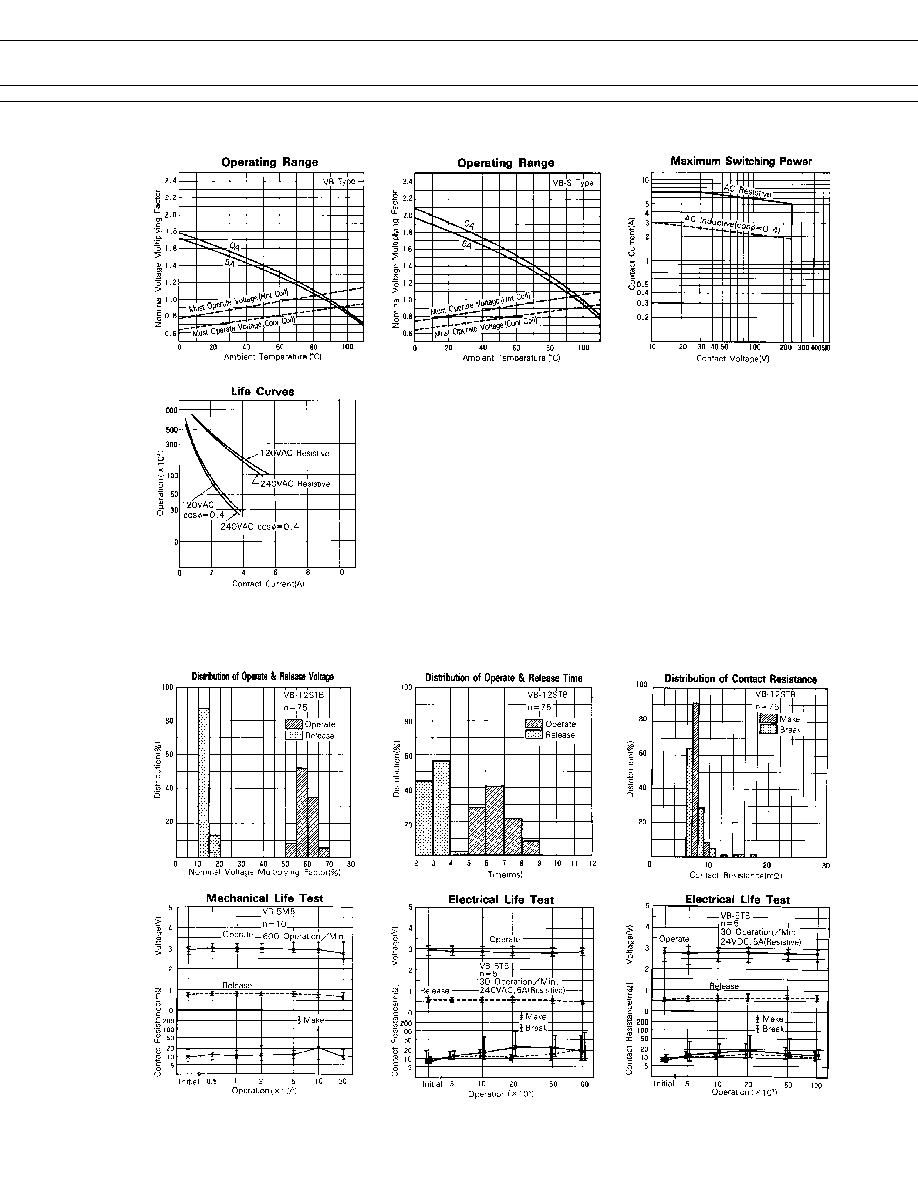
CHARACTERISTIC DATA
Note: All values in the table are measured at 20
∞
C.
5
VB SERIES
s
REFERENCE DATA
6
VB SERIES
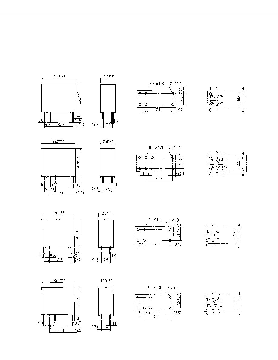
s
DIMENSIONS
VB-K type (Plastic sealed type)
q
Dimensions
q
Schematics
(BOTTOM VIEW)
q
PC board mounting
hole layout
(BOTTOM VIEW)
VB-M type
VB type
VB-MK type (Plastic sealed type)
Unit: mm

7
VB SERIES
VB-MC type (Plastic sealed type with tape)
VB-C type (Plastic sealed type with tape)
Unit: mm
© 2003 Fujitsu Components America, Inc. All company and product names are trademarks or registered trademarks
of their respective owners. Rev. 02/18/2003
Japan
Fujitsu Component Limited
Gotanda-Chuo Building
3-5, Higashigotanda 2-chome, Shinagawa-ku
Tokyo 141, Japan
Tel: (81-3) 5449-7010
Fax: (81-3) 5449-2626
Email: promothq@ft.ed.fujitsu.com
Web: www.fcl.fujitsu.com
North and South America
Fujitsu Components America, Inc.
250 E. Caribbean Drive
Sunnyvale, CA 94089 U.S.A.
Tel: (1-408) 745-4900
Fax: (1-408) 745-4970
Email: marcom@fcai.fujitsu.com
Web: www.fcai.fujitsu.com
Europe
Fujitsu Components Europe B.V.
Diamantlaan 25
2132 WV Hoofddorp
Netherlands
Tel: (31-23) 5560910
Fax: (31-23) 5560950
Email: info@fceu.fujitsu.com
Web: www.fceu.fujitsu.com
Asia Pacific
Fujitsu Components Asia Ltd.
102E Pasir Panjang Road
#04-01 Citilink Warehouse Complex
Singapore 118529
Tel: (65) 6375-8560
Fax: (65) 6273-3021
Email: fcal@fcal.fujitsu.com
www.fcal.fujitsu.com
Fujitsu Components
International
Headquarter
Offices