 | ÐлекÑÑоннÑй компоненÑ: VG-48 | СкаÑаÑÑ:  PDF PDF  ZIP ZIP |
28. VG WEB Series (184-191)1
DISCONTINUED
s
FEATURES
q
UL, CSA recognized, TV-5 rated
q
1 form A (SPST-NO) or 1 form C (SPDT) contact
q
Reliable, low power consumption miniature power relay
--Surge strength 7,000 V
q
Slim type--meets high density mounting requirement
q
Easy circuit design with completely separated terminal
arrangement (coil and contact terminals)
q
Plastic sealed type backfilled with nitrogen available
q
Environmentally friendly cadmium free contact type is
available
(a)
Series Name
VG: VG Series
(b)
Nominal Voltage
Refer to the COIL DATA CHART
(c)
Contact Rating
Nil : 3 A
H : 5 A
T : 5 A (only TV-5)
(d)
Contact Arrangement
Nil : 1 form C (SPDT)
M : 1 form A (SPST-NO)
(e)
Coil Type
Nil : Standard type
S : High sensitivity type (only 3 A type available)
(f)
Contact Material (Rating)
Nil : Gold overlay silver-nickel (3 A, 5 A)
Nil : Silver alloy (only TV-5)
E : Silver-nickel (3 A, 5 A)
(g)
Enclosure
Nil : Flux free type
C : Plastic sealed type (with tape)
K : Plastic sealed type
(h)
Standard
UL : UL, CSA approved type
s
ORDERING INFORMATION
VG 12
H
M
S
E
K
UL
[Example]
(a) (*) (b) (c) (d) (e) (f )
(g)
(h)
VG SERIES
POWER RELAY
1 POLE--3A to 5 A
(CADMIUM FREE CONTACTS TYPE)
Note: Actual marking omits the hyphen (-) of (*)
1
2
VG SERIES
DISCONTINUED
s
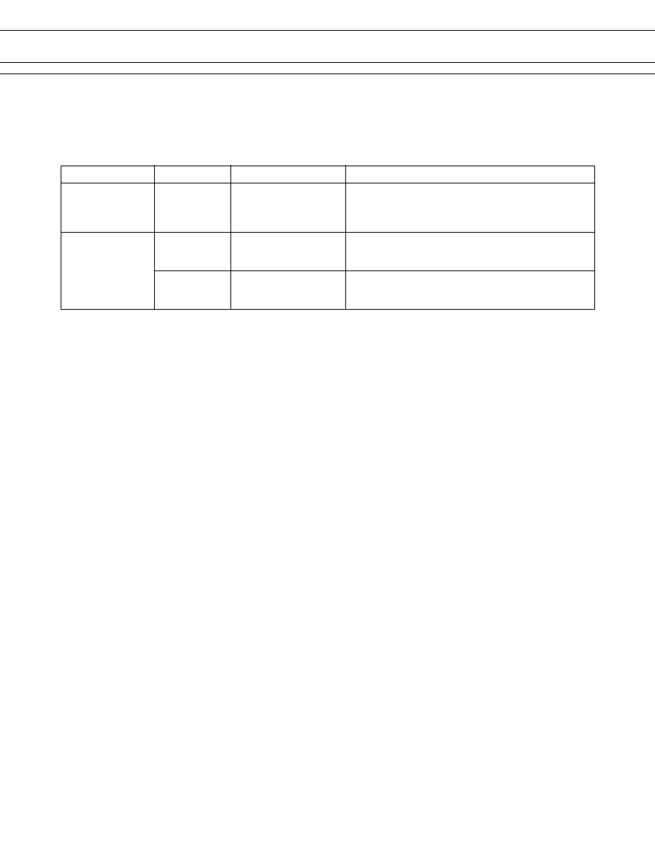
SAFETY STANDARD AND FILE NUMBERS
UL508, 873 (File No. E56140)
C22.2 No. 1, No. 14 (File No. LR35579)
Please note that UL/CSA ratings may differ from the standard ratings.
Type
Nominal voltage
Contact rating
TV-Rating
VG-TM
5 to 48 VDC
TV-5 120 VAC
1/8 HP 120 VAC/240 VAC
5 A 24 VDC/240 VAC resistive (*)
Pilot duty C 150
General
VG-H
5 to 48 VDC
1/8 HP 120 VAC/240 VAC
5 A 24 VDC/120 VAC resistive
Pilot duty C 150
VG
5 to 48 VDC
1/10 HP 120 VAC/240 VAC
3 A 30 VDC/120 VAC resistive
Pilot duty D 150
*
Only UL approval
3
VG SERIES
DISCONTINUED
Standard Type
High Sensitive Type
Item
TV-5 Type
5 A Type
3 A Type
3 A Type
VG-( ) TM
VG-( ) H
VG
VG-S
VG-( ) HE
VG-E
VG-SE
Contact
Arrangement
1 form A (SPST-NO) 1 form A (SPST-NO) or 1 form C (SPDT)
Material
Silver alloy
Gold overlay silver alloy (VG-H, VG), silver alloy (VG-HE,E)
Style
Single
Resistance (initial) (at 1 A 6 VDC)
Maximum 200 m
Maximum 70 m
(VG-H,VG), Max. 100 m
(VG-HE, E)
Rating (resistive)
5 A 120 VAC 3 A 120 VAC
5 A 24 VDC 3 A 30 VDC
Maximum Carrying Current
5 A
Maximum Switching Power
1,000 VA, 150 W 500 VA, 90 W
Maximum Switching Voltage
250 VAC, 150 VDC
Maximum Switching Current
5 A 3 A
Minimum Switching Load*
1
10 mA 5 VDC (VG-H,VG), 100 mA 5 VDC (VG-TM,VG-HE, E)
Coil
Nominal Power (at 20
°
C)
0.36 to 0.4 W
0.21 to 0.26 W
Operate Power (at 20
°
C)
0.18 to 0.2 W
0.102 to 0.13 W
Operating Temperature
40
°
C to +70
°
C (no frost)
40
°
C to +85
°
C (no frost)
Time Value
Operate (at nominal voltage)
Maximum 10 ms
Release (at nominal voltage)
Maximum 5 ms
Insulation
Resistance (at 500 VDC)
Minimum 1,000 M
between open
900 VAC 1 minute 750 VAC 1 minute
Dielectric contacts
Strength
between coil
4,000 VAC 1 minute
and contacts
Surge Strength
7,000 V (at 1.2
×
50
µ
s)
Life
Mechanical 1
×
10
7
operations minimum
Electrical
1
×
10
5
operations minimum (at contact rating)
Other
Vibration Misoperation
10 to 55 Hz (double amplitude of 1.5 mm)
Resistance
Endurance
10 to 55 Hz (double amplitude of 1.5 mm)
Shock Misoperation
100 m/s
2
(11
±
1 ms)
Resistance
Endurance
1,000 m/s
2
(6
±
1 ms)
Weight
Approximately 12 g
s
SPECIFICATIONS
*
1
Minimum switching loads mentioned above are reference values. Please perform the confirmation test with the actual
load before production since reference values may vary according to switching frequencies, environmental conditions
and expected reliability levels.
4
VG SERIES
DISCONTINUED
s
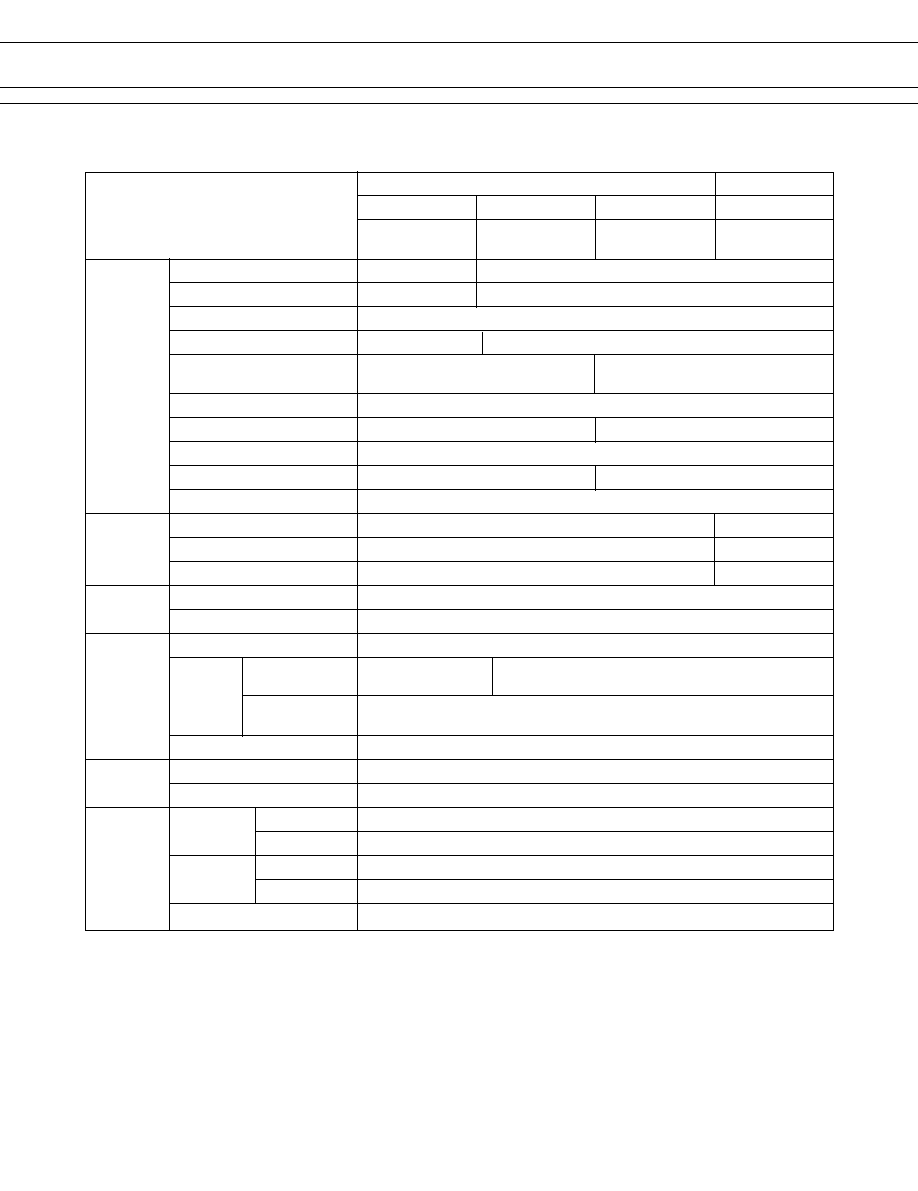
COIL DATA CHART
MODEL
Nominal
Coil
Must
Must
Nominal
TV
Standard Type
resistance
operate
release
voltage
(
±
10%)
voltage
voltage
power
5 A Type
5 A Type
3 A Type
VG- 5TM
VG- 5H (M) (E)
VG- 5 (M) (E)
5 VDC
69
35 VDC
0.25 VDC
360 mW
VG- 6TM
VG- 6H (M) (E)
VG- 6 (M) (E)
6 VDC
100
4.2 VDC
0.3 VDC
360 mW
VG- 9TM
VG- 9H (M) (E)
VG- 9 (M) (E)
9 VDC
225
6.3 VDC
0.45 VDC
360 mW
VG-12TM
VG-12H (M) (E)
VG-12 (M) (E)
12 VDC
400
8.4 VDC
0.6 VDC
360 mW
VG-18TM
VG-18H (M) (E)
VG-18 (M) (E)
18 VDC
870
12.6 VDC
0.9 VDC
380 mW
VG-24TM
VG-24H (M) (E)
VG-24 (M) (E)
24 VDC
1,450
16.8 VDC
1.2 VDC
400 mW
VG-48TM
VG-48H (M) (E)
VG-48 (M) (E)
48 VDC
6,000
33.6 VDC
2.4 VDC
390 mW
VG- 5 (M) S (E)
5 VDC
120
3.5 VDC
0.25 VDC
210 mW
VG- 6 (M) S (E)
6 VDC
150
4.2 VDC
0.3 VDC
240 mW
VG- 9 (M) S (E)
9 VDC
325
6.3 VDC
0.45 VDC
250 mW
VG-12 (M) S (E)
12 VDC
575
8.4 VDC
0.6 VDC
250 mW
VG-18 (M) S (E)
18 VDC
1,400
12.6 VDC
0.9 VDC
240 mW
VG-24 (M) S (E)
24 VDC
2,230
16.8 VDC
1.2 VDC
260 mW
High Sensitive
T
ype
Standard
T
ype
s
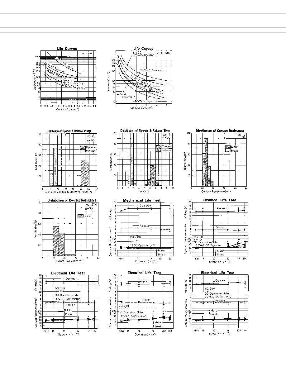
CHARACTERISTIC DATA
Note: All values in the table are measured at 20
°
C.
5
VG SERIES
DISCONTINUED
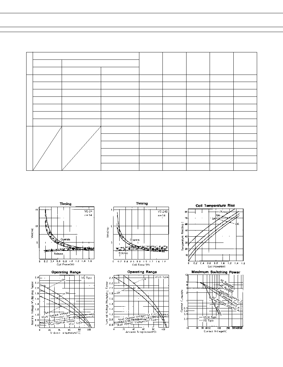
s
REFERENCE DATA