Dorado, Page 1
Part No. 01-002 Rev. 1.0≠110802
PRODUCT PREVIEW
Industry's Lowest Cost High-efficiency
DC/DC Converter
Industry Standard Quarter Brick Pinout and
Footprint
Typical Efficiency: 83% at 3.3V, 15A
Low Profile
Very Low Common-mode Noise for a
Commercial DC/DC Converter
Constant Switching Frequency
Remote Sense
Uses Innovative Control and Power Topology
for Lower Parts Count
Single Board Design
Optional Low Profile Heatsink for Improved
Thermal Performance
Header with M3 Metal Inserts for Mechanical
Connection to PCB
Two Year Warranty
DORADO
Control Functions
Microprocessor Controlled
Primary-side Enable, Choice of Logic
Protection Features
Over Temperature Protection
Over Voltage Protection
Over Current Protection
Over/Under Input Voltage Protection
Typical Characteristics
Output Setpoint Accuracy:
±1%
Load Regulation:
±0.2%
Line Regulation:
±0.2%
Regulation over Line, Load, and Temperature:
±2%
Low Output Ripple
Industry Standard Output Trim
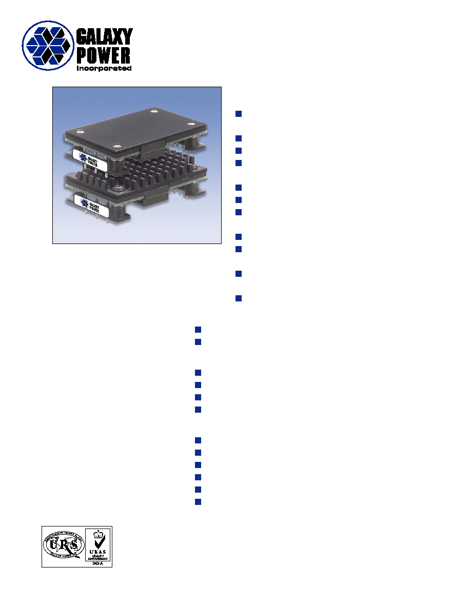
The Dorado is available with an optional low profile
heatsink for improved thermal performance.
24V or 48V Input, 1.5V, 1.8V, 2.0V, 2.5V, 3.3V DC,
20A Output or 5.0V DC, 15A Output
Dorado, Page 2
Part No. 01-002 Rev. 1.0≠110802
PRODUCT PREVIEW
General Specifications
Operating Temperature
-40
∞C to +100∞C
Storage Temperature
-55
∞C to +125∞C
Relative Humidity
10% to 95% RH,
Non-condensing
Vibration
2 to 9Hz, 3mm disp.,
9 to 200Hz 1g
Material Flammability
UL V-0
Weight
30 grams
MTBF
Telcordia (Bellcore)
2,000,000 hours
General Specifications
V
IN
= 48V
DC
, T
A
@25
∞C, 300 LFM Airflow, V
OUT
= 3.3V, I
OUT
= full load unless otherwise noted.
Available output power depends on ambient temperature and good thermal management. (See application graphs for limits.)
Input Characteristics
Parameter
Min
Typ
Max
Units
Operating Input Voltage
36
48
75
V
DC
Input Current
4
A
Input Capacitance
2
µF
Input Hysteresis, Low Line
2
V
DC
Output Characteristics
Regulation Over Line, Load & Temperature
98
102
%V
NOM
Voltage Ripple
20
mV
RMS
Voltage Ripple, 20MHz BW
100
mV
P≠P
Current Range
0
20
A
Current Limit Inception
22
27
A
Short Circuit Current, Peak (see Note below)
30
A
Output Transient Response, 50% to 75% load change, 1A/
µsec
5
%V
OUT
Settling Time to
±1%
300
µS
Turn-on Time to 98%Vnom
30
mS
Output Overshoot at Turn-on
1
%V
OUT
Trim Range
60
110
%V
OUT
Overvoltage Protection, Latching
130
%V
OUT
Isolation
Isolation Test Voltage, Input/Output (Basic)
2000
V
DC
Isolation Resistance
10
M
Features
Overtemperature Protection, Thermal Sensor, Latching*
117
∞C
Switching Frequency, Fixed
300
kHz
Notes: During short circuit, converter will shut down and attempt to restart once per second. The average current during this
condition will be very low and the device can be safely left in this condition continuously. For specific output voltage
specifications, see the corresponding detailed data sheet.
*PCB less than 130
∞C
Approvals and Standards
UL and c-UL Recognized Component, TUV,
UL60950, CSA 22.2 No. 950, IEC/EN 60950**
EMC Characteristics:
Designed to meet emission and immunity
requirements per EN55022, CISPR 22, Class B,
and CISPR 24.
** An external fuse shall be used to comply with the
requirements.
Dorado, Page 3
Part No. 01-002 Rev. 1.0≠110802
PRODUCT PREVIEW
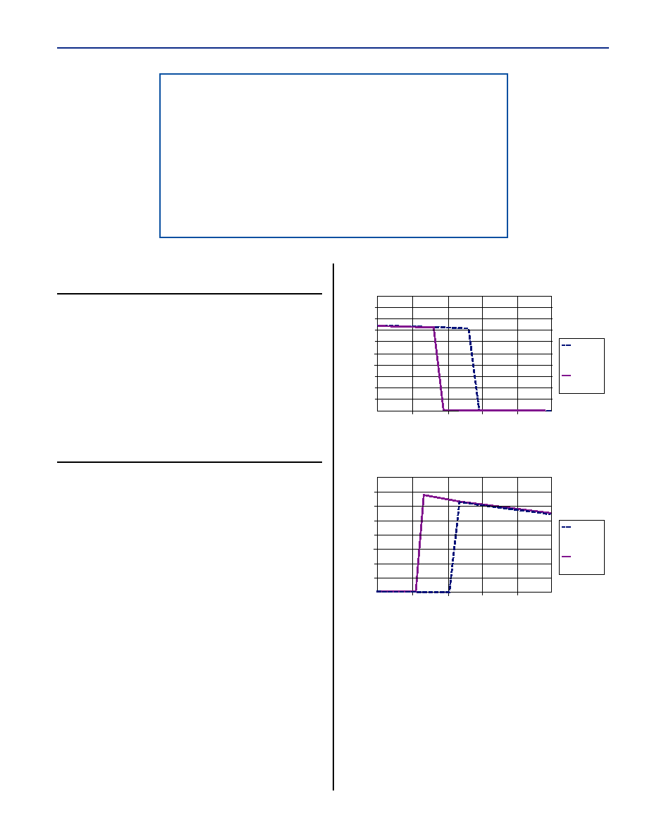
Undervoltage Lockout
30
32
36
34
40
38
Input Voltage (V)
Input Curr
ent
Voltage
Rising
Voltage
Falling
Overvoltage Lockout
75
76
78
77
80
79
Input Voltage (V)
Input Curr
ent
Voltage
Rising
Voltage
Falling
CoolConverter
TM
Galaxy's proprietary CoolConverter
TM
provides:
∑ Patent Pending single-stage power conversion
architecture, control, and magnetic design allow
unprecedented power density and efficiency in an isolated
power supply.
∑ An advanced microcontroller reduces parts count while
adding features, performance, and flexibility in the design.
Protection and Control
Valid Input Voltage Range:
The converter measures the input voltage and will not
allow operation outside of the input voltage
specification. As shown by the graphs, hysteresis is
added to both the high and low voltage to prevent the
converter from turning on and off repeatedly when the
voltage is held near either voltage extreme. At low line
this assures the maximum input current is not exceeded;
at high line this assures the semiconductor devices in
the converter are not damaged by excessive voltage
stress.
ON/OFF Logic Option:
The ON/OFF control logic can be either Negative
(standard) or Positive to enable the converter. For
Negative logic, the ON/OFF pin is brought below 1.0 V
with respect to the ≠INPUT pin to enable the converter.
For Positive logic, the ON/OFF pin is brought to greater
than 4.0 V with respect to the ≠INPUT pin. To request
the Positive logic version, add the suffix (P) to the
standard part number. The positive version has a built-
in pull up resistor of approximately 100 k
.
Application Notes
Dorado, Page 4
Part No. 01-002 Rev. 1.0≠110802
PRODUCT PREVIEW
Output Over Voltage Protection:
The output voltage is constantly monitored by the
microprocessor and a parallel regulation path with an
independent reference. If the output voltage exceeds
the over-voltage specification, the microprocessor will
latch the converter off. To turn the converter on requires
either cycling the ON/OFF pin or power to the
converter. This advanced feature prevents the converter
from damaging the load if there is a converter failure or
application error. If non-latching is required, consult
factory.
Thermal Shutdown:
The printed circuit board temperature is measured
using a semiconductor sensor. If the maximum rated
temperature is exceeded, the converter is latched off. To
re-enable the converter requires cycling the ON/OFF
pin or power to the converter. If non-latching is
required, consult factory.
Control Options:
As the behavior of the circuit is determined by
firmware in the microcontroller, specific customer
requirements such as
∑ non-latching thermal protection
∑ custom valid input voltage range
∑ controlled delay from initiating an ON/OFF
signal for power sequencing
can be accomplished with no change to hardware.
The standard behavior was chosen based on system
design experience but we understand that customers
often have their own requirements.
Please consult Galaxy Power for your special needs.
Remote Sense:
The output voltage is regulated at the point where the
sense pins connect to the power output pins. Total sense
compensation should not exceed 0.4V or 10% of Vout,
whichever is greater.
Safety:
An external input fuse must always be used to meet
these safety requirements.
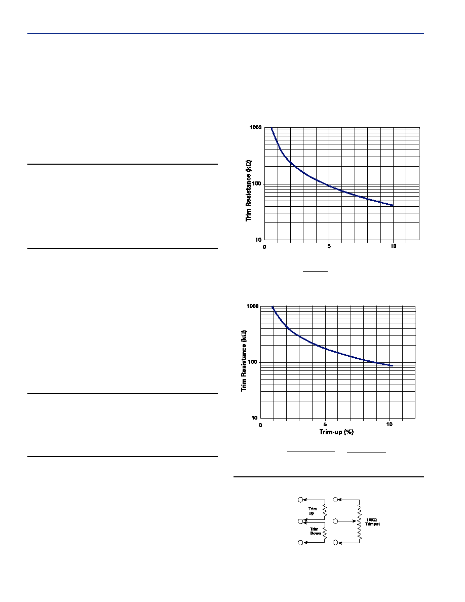
Trim:
To trim the output voltage higher, connect the
required trim resistor from the Trim pin to the +Sense
pin. To trim the output voltage lower, connect the
required trim resistor from the Trim pin to the ≠Sense
pin. See diagram below.
Trim-down (%)
Trim-down
R
TRIM-DOWN
=
100
≠ 2
5.11k
%
{ }
Trim-up
R
TRIM-UP
=
V
O
(100+
%)
≠
(100+
2%)
5.11k
1.225%
%
{
}
External Output Trimming
Application Notes
+ Sense
Trim
≠ Sense
Dorado, Page 5
Part No. 01-002 Rev. 1.0≠110802
PRODUCT PREVIEW
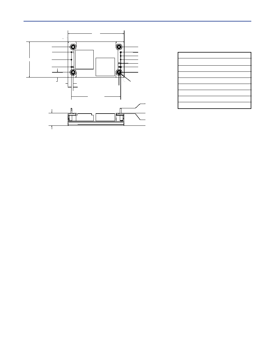
.50
(opt. L = .465)
.50
.030
.20
0
SIDE VIEW
BOTTOM VIEW
A
A
B
A
A
MOUNTING INSERT
CONNECTED TO CASE PIN
MOUNTING INSERT
M3 X 0.5 4 PLACES
.070
2.000
PIN TO PIN
.210
.210
1.45
2.28
1.030
.815
PIN 1
.515
PIN 2
.215
PIN 3
0
PIN 4
.215
1.030
PIN 8
.815
PIN 7
.665
PIN 6
.515
PIN 5
.365
0
1
.
860
0
Pin
Function
Pin Dia. (in.)
1
≠ Input
0.040
2
On/Off
0.040
3
+ Input
0.040
4
+ Output
0.060
5
+ Sense
0.040
6
Trim
0.040
7
≠ Sense
0.040
8
≠ Output
0.060
Notes:
1. Mechanical tolerances
x.xxx in. =
±0.005 in.
x.xx in. =
±0.01 in.
2. Pin material: brass with tin/lead plating over nickel
3. Workmanship: Meets or exceeds IPC-A-610B Class II
PACKAGE DETAIL