
Genesis Microchip Publication
Genesis Microchip Inc.
2150 Gold Street, Alviso, P.O. Box 2150, CA USA 95002 Tel: (408) 262-6599 Fax: (408) 262-6365
165 Commerce Valley Dr. West, Thornhill, ON Canada L3T 7V8 Tel: (905) 889-5400 Fax: (905) 889-5422
George Thangiah Complex(E), 2nd Floor, 80 Feet Road, Jeevan Bhima Nagar, Bangalore 560 075, India, Tel 91-80-526 3878 Fax 91-80-529 6245
4F , No 57 , Sing Jung Road , NeiHu , Taipei, Taiwan 114 .R.O.C Tel: 886-2-2791-0118 Fax: 886-2-2791-0196
143-37 Hyundai Tower, #902, Samsung-dong, Kangnam-gu, Seoul, Korea 135-090 Tel 82-2-553-5693 Fax 82-2-552-4942
Rm2614-2618 Shenzhen Office Tower, 6007 Shennan Blvd, 518040, Shenzhen, Guandong, P.R.C., Tel (0755)386-0101, Fax (0755)386-7874
2-9-5 Higashigotanda, Shinagawa-ku, Tokyo, 141-0022, Japan, Tel 81-3-5798-2758, Fax 81-3-5798-2759
www.genesis-microchip.com /
info@genesis-microchip.com
DATA SHEET
gmZAN2
Flat Panel Monitor Controller IC
Publication number: C0022-DAT-01D
Publication date: August 2002
gmZAN2 Data Sheet
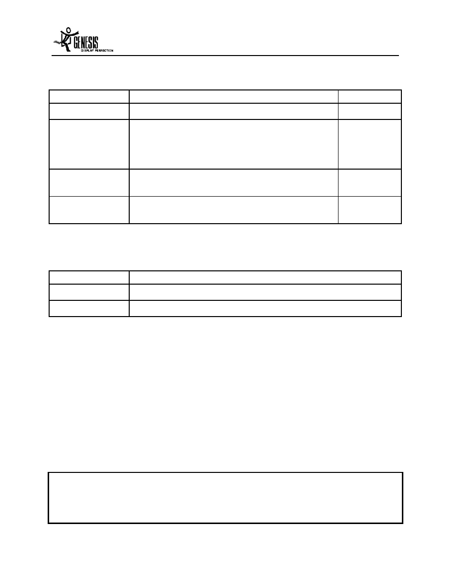
Document History:
Revision Description Date
C0022-DAT-01A
Initial Release
June 2001
C0022-DAT-01B
4 pins were changed from reserve to three VSS (pin 5,
59 and 147) one VDD (pin 60). Voltages have been
swapped (pin 40 and108) from 2.5V to 3.3V and vice
versa (pin 125); Table 3 and Table 6
July 2001
C0022-DAT-01C
Added ESM in section 1 and 2.1.15 and updated
section 3 with measured values
October 2001
C0022-DAT-01D
Changed max. external OSD Clock frequency to 80MHz
in section 2.8.4 and in Table 18 and Figure 14
August 2002
Related Documents:
Doc Number
Title
C0022-PBR-01C
gmZAN2 Product Brief
C0021-DAT-01F
gmZAN1 Data Sheet
Copyright 2002, Genesis Microchip Inc. All Rights Reserved.
Genesis Microchip Inc. reserves the right to change or modify the information contained herein without
notice. It is the customer's responsibility to obtain the most recent revision of the document. Genesis
Microchip Inc. makes no warranty for the use of its products and bears no responsibility for any errors or
omissions that may appear in this document.

gmZAN2 Data Sheet
August 2002
-iii-
C0022-DAT-01D
Table of Contents
1.
Overview .......................................................................................................................... 1
1.1
Features .................................................................................................................... 2
1.2
Pin Out Diagram........................................................................................................ 3
1.3
Pin Description .......................................................................................................... 4
1.4
System-level Block Diagram ................................................................................... 10
1.5
Operating Modes..................................................................................................... 11
1.5.1
Native ................................................................................................................ 11
1.5.2
Slow DCLK ........................................................................................................ 11
1.5.3
Zoom ................................................................................................................. 12
1.5.4
Downscaling (Recovery).................................................................................... 12
1.5.5
Destination Stand Alone.................................................................................... 12
1.5.6
Source Stand Alone .......................................................................................... 12
2.
Functional Description ................................................................................................. 13
2.1
Overall Architecture................................................................................................. 13
2.2
Clock Recovery Circuit ............................................................................................ 13
2.2.1
Reset................................................................................................................. 15
2.2.2
Sampling Phase Adjustment ............................................................................. 15
2.2.3
Source Timing Generator .................................................................................. 15
2.3
Analog-to-Digital Converter ..................................................................................... 16
2.3.1
Pin Connection .................................................................................................. 16
2.3.2
Display Mode Support ....................................................................................... 18
2.4
Input Timing Measurement...................................................................................... 18
2.4.1
Source Timing Measurement ............................................................................ 18
2.4.2
IRQ Controller ................................................................................................... 19
2.5
Data Path ................................................................................................................ 20
2.5.1
Scaling Filter...................................................................................................... 20
2.5.2
Gamma Table.................................................................................................... 20
2.5.3
RGB Offset........................................................................................................ 21
2.5.4
Panel Data Dither .............................................................................................. 21
2.5.5
Panel Background Color.................................................................................... 21
2.6
Panel Interface ........................................................................................................ 21
2.6.1
TFT Panel Interface Timing Specification.......................................................... 21
2.6.2
Power Manager ................................................................................................. 24
2.6.3
Energy Spectrum Management (ESM).............................................................. 26
2.6.4
Panel Interface Drive Strength .......................................................................... 26
2.7
Host Interface .......................................................................................................... 26
2.7.1
Serial Communication Protocol ......................................................................... 27

gmZAN2 Data Sheet
August 2002
-iv-
C0022-DAT-01D
2.7.2
Four bit Parallel Host interface .......................................................................... 29
2.7.3
Multi-Function Bus (MFB).................................................................................. 31
2.8
On-Screen Display Control...................................................................................... 31
2.8.1
OSD Color Map ................................................................................................. 31
2.8.2
On-Chip OSD Controller.................................................................................... 31
2.8.3
Built-in OSD Fonts............................................................................................. 34
2.8.4
External OSD Support....................................................................................... 35
2.9
On-chip TCLK Oscillator.......................................................................................... 37
2.9.1
External Oscillator mode ................................................................................... 37
2.9.2
Internal Oscillator mode .................................................................................... 38
2.10
Sleep Mode Power Down........................................................................................ 41
3.
Electrical Characteristics ............................................................................................. 42
4.
Ordering Information .................................................................................................... 43
5.
Mechanical Dimensions ............................................................................................... 44

gmZAN2 Data Sheet
August 2002
-v-
C0022-DAT-01D
Table of Figures
Figure 1.
gmZAN2 Pin Diagram....................................................................................... 3
Figure 2.
Typical Stand-alone Configuration.................................................................. 10
Figure 3.
Block Diagram for gmZAN2 ............................................................................ 13
Figure 4.
Clock Recovery Circuit ................................................................................... 14
Figure 5.
Capture Window ............................................................................................. 16
Figure 6.
gmZAN2 Data Path......................................................................................... 20
Figure 7.
Timing Diagrams of the TFT Panel Interface (one pixel per clock)................. 23
Figure 8.
Data latch timing of the TFT Panel Interface .................................................. 24
Figure 9.
Panel Power Sequence .................................................................................. 25
Figure 10.
Timing Diagram of the gmZAN2 Serial Communication ................................. 28
Figure 11.
Timing diagram for read/write using 4-bit Parallel Host Interface ................... 30
Figure 12.
On-Chip OSD Window Location ..................................................................... 33
Figure 13.
Built-in OSD Fonts .......................................................................................... 35
Figure 14.
External OSD Interface Data Latch Timing..................................................... 36
Figure 15.
Using an External Oscillator ........................................................................... 38
Figure 16.
Using an Internal Oscillator............................................................................ 39
Figure 17.
Internal Oscillator output at TCLK................................................................... 39
Figure 18.
Parasitic Capacitance Sources....................................................................... 40
Figure 19.
160 pin PQFP Package Dimensions .............................................................. 44