PRELIMINARY
GENLINX
TM
II
EB9024 Evaluation Board
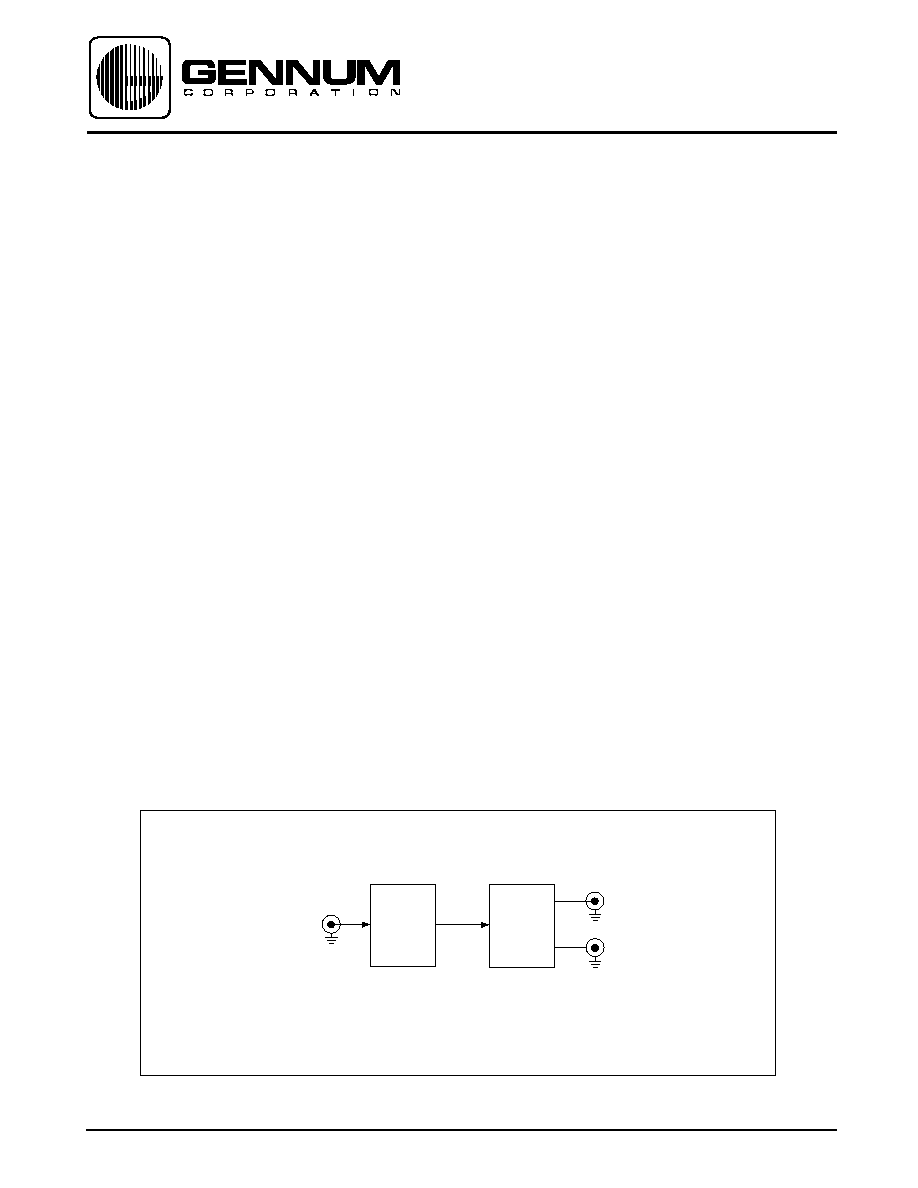
EB9024 BLOCK DIAGRAM
Document No. VB2932 - 1
INTRODUCTION
The EB9024 is an evaluation and reference design platform
for the GENLINX
TM
II
GS9024 Equalizer and the GS9028
Cable Driver.
CIRCUIT DESCRIPTION
A functional block diagram is shown below and illustrates
the primary circuit functions. These include equalization
and driving 75
co-axial cables. A complete schematic is
also included.
The EB9024 accepts a serial digital data input signal
which first goes into the GS9024 equalizer. Equalization
of the input signal is completely automatic for signal
attenuation due to cable length from 0dB to in excess of
30dB. The signal strength/carrier detect output of the
equalizer, which is proportional to the amount of equalization
taking place, is available via test point TP1. Also available
as an output, is the equalizer "Output Eye Monitor" signal
via a SMA connector (J2). The signal strength/carrier
detect and Output Eye Monitor are useful diagnostic
outputs.
After equalization, the differential data signal is supplied
to the GS9028 cable driver which provides two
complementary data outputs at BNC connectors J3 and
J4. The GS9028 is configured to drive 75
co-axial
cables with SMPTE defined 800mV levels.
BOARD SET-UP AND TEST
The CD_ADJ input of the GS9024 is biased via a resistor
network including a potentiometer allowing the user to
adjust the level at which loss of carrier is detected. For a
detailed description of the CD_ADJ voltage level versus
muting threshold refer to the GS9024 data sheet. Turning
the potentiometer completely clockwise allows for maxi-
mum possible cable length equalization. In addition, the
GS9024 outputs can be put in a HIGH-Z state by putting
jumper JMP1 into the 1-2 position.
To verify operation of the EB9024, a source of serial digital
video should be applied to the input BNC connector using
75
co-axial cable. Using a signal source that is not
compliant to the SMPTE standards, can provide mislead-
ing results for equalizer cable length performance. The
output data stream is available at the serial output and can
be supplied to a D to A converter for verification via a
monitor. Note that jumper JMP1 must be in the 2-3 position
such that the equalizer outputs are enabled.
The power supply requirement for the EB9024 is +5V for
VCC at a current rating of 86mA (nominally).
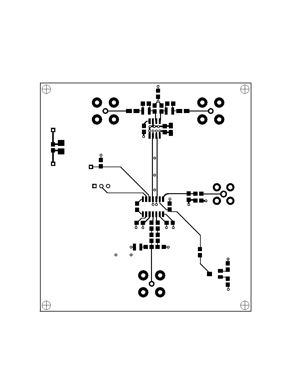
PCB DETAILS
The EB9024 is a four layer printed circuit board con-
structed of standard FR-4 material and measures approxi-
mately 3.5" by 3.25". Ground and power plane layers are
internal to the board with signal layers on the top and
GS9024
EQUALIZER
SERIAL
DATA
INPUT
SERIAL
DATA
OUTPUTS
GS9028
CABLE
DRIVER
1

VB2932 - 1
2
bottom of the board. Components are mounted both on the
top and bottom sides. The silkscreen (top and bottom) and
all four layers are shown on the following pages. Note the
following special artwork features used to optimize perform-
ance:
- A continuous ground plane is provided underneath all high
speed traces avoiding impedance discontinuities and en-
suring maximum signal integrity
- Copper on the power and ground planes has been re-
moved from the area surrounding the center pin of the output
BNC connectors and from underneath the output compo-
nents of the GS9028 cable driver. The purpose of these
cutouts is to reduce the effect of the capacitance added by
the connector and the pads of the components.
- The ground plane associated with the input BNC connector
and input components is isolated from the main board
ground. The purpose of this is to provide a differential input
signal to the equalizer.
APPLICATIONS
The EB9024 evaluation board is designed to show the
characteristics of the GS9024 Equalizer and the GS9028
Cable Driver. This board can also be used as a stand alone
non-reclocking distribution amplifier for serial digital video
signals.
CAUTION
ELECTROSTATIC
SENSITIVE DEVICES
DO NOT OPEN PACKAGES OR HANDLE
EXCEPT AT A STATIC-FREE
Gennum Corporation assumes no responsibility for the use of any circuits described herein and makes no representations that they are free from patent infringement.
Please be advised that this preliminary document does not conform to Gennum's ISO9001 standards.
© Copyright March 1998 Gennum Corporation. All rights reserved. Printed in Canada.