 | –≠–ª–µ–∫—Ç—Ä–æ–Ω–Ω—ã–π –∫–æ–º–ø–æ–Ω–µ–Ω—Ç: GA3216 | –°–∫–∞—á–∞—Ç—å:  PDF PDF  ZIP ZIP |

GA3216 PRELIMINARY DATA SHEET
GA
32
16
Doc.No.24501 - 3 [Rev. February 2004]
1 of 14
FEATURES
∑ efficient, high fidelity 1 or 2-channel WDRC signal
processing
∑ fully programmable via serial data interface
∑ SOUND
DESIGN
TM high-fidelity audio quality
∑ four trimmer inputs plus volume control
∑ flexible trimmer/parameter assignments
∑ optional two-terminal or three-terminal trimmers
∑ choice of wideband or independent 2-channel level
detection
∑ choice of two strategies for AGC-I parametric
adjustment
∑ 6, 12 or 24 dB/octave band split filter or configurable
as single-channel compressor.
∑ in-channel, low level squelch control (1:2 expansion)
∑ output compression limiting (AGC-O)
∑ flexible pre- and post-emphasis filters
∑ four independent memories
∑ pulse-density-modulated output stage drives zero-
bias 2-terminal receivers
thinSTAXTM PACKAGING
Hybrid typical dimensions:
0.190 x 0.123 x 0.060in
(4.82 x 3.12 x 1.52mm)
DESCRIPTION
The GA3216 hybrid is a trimmer-configurable DSP system
based on a two-channel compression circuit. It can
efficiently replace traditional hearing-aid compression
circuits without compromising fundamental performance
requirements.
A trimmer interface supports manual circuit configuration. It
continuously monitors trimmer positions and translates them
into the hearing-aid parameters of choice. A serial data
interface provides full programmability both at the factory
and in the field.
The GA3216 includes in-channel squelch to attenuate
microphone and circuit noise in quiet environments. It also
includes low-distortion compression limiting and
programmable high and low cut filters as well as five
configurable equalization filters. Unused blocks can be
powered down to save battery current, for example, when
using the device in single-channel mode.
The GA3216 Hybrid code programmed into the GC5020
controller chip is '1'.
This datasheet is part of a set of documents available for
this product. Please refer to
Getting Started with Foundation
Digital
, document #25786 for a list of other documents.
BLOCK DIAGRAM
MGND
GND1
IN
T
VREG
SDA
MS
MS2
TR4
TR3
TR2
TR1
VC
VB
GND2
PGND
OUT -
OUT+
VBP
VREG2
A/D
SQUELCH
SQUELCH
HP
LP
TRIMMER INTERFACE
24db/oct
BAND SPLIT
FILTER
COMPRESSOR
COMPRESSOR
PROGRAMMING
INTERFACE
EEPROM
REGULATOR
TWIN DETECTOR
PEAK
CLIPPING
D/A
HBRIDGE
TONE
GENERATOR
GA3216
EQ1
EQ2
EQ5
VC GAIN
EQ3
AGC-O
TWIN DETECTOR
EQ4
T-coil EQ
1st or 2nd
ORDER
1st to 3rd
ORDER
LC
HC
TWIN DETECTOR
TWIN DETECTOR
19
14
13
12
1
16
17
15
20
5
2
3
4
18
6
7
9
8
10
11
FOUNDATIONTM Digital
Single or Dual Channel
DSP Compression System
24501 - 3
2 of 14
GA
32
16
ABSOLUTE MAXIMUM RATING
PAD CONNECTION
Operating Temperature Range
-10∞C to 40∞C
Storage Temperature Range
-20∞C to 70∞C
Absolute Maximum Power Dissipation
25mW
Input ESD Voltage
2000V
Maximum Operating Supply Voltage
1.5VDC
Absolute Maximum Supply Voltage
2VDC
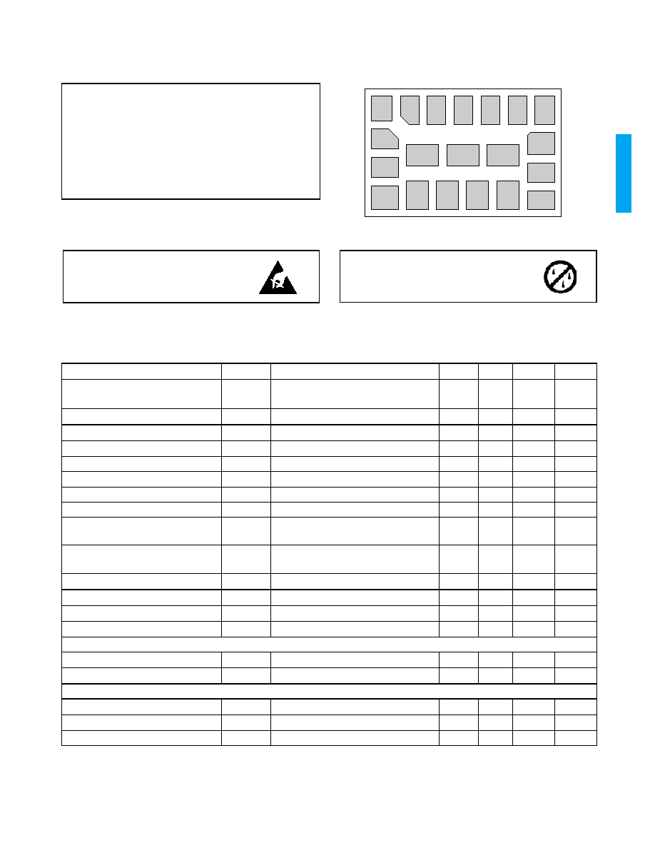
CAUTION
ELECTROSTATIC
SENSITIVE DEVICES
DO NOT OPEN PACKAGES OR HANDLE
EXCEPT AT A STATIC-FREE WORKSTATION
VC
TR2
TR3
TR1
GND1
TR4
PGND
OUT+
OUT -
IN
T
VBP
MGND
MS
SDA
VB
MS2
VREG
GND2
VREG2
18
17
16
19
13
14
15
12
8
9
10
20
2
3
4
5
1
7
6
11
CAUTION
LEVEL 3 MOISTURE
SENSITIVE DEVICES
DO NOT OPEN PACKAGES EXCEPT UNDER
CONTROLLED CONDITIONS
ELECTRICAL CHARACTERISTICS
Conditions: Supply Voltage V
B
= 1.3V; Temperature = 25∞C, 16 kHz bandwidth
PARAMETER
SYMBOL
CONDITIONS
MIN
TYP
MAX
UNITS
Hybrid Current
AMP
AMP
All functions, 24kHz sampling rate
All functions, 32kHz sampling rate
-
-
540
650
-
-
µA
µA
Minimum Operating Supply Voltage
V
BOFF
Ramp down
0.95
-
0.980
V
Supply Voltage Turn on Threshold
V
BON
Ramp up
1.065
1.10
1.160
V
Supply Voltage Hysteresis
V
BON -
V
BOFF
-
150
-
mV
Low Battery Warning Voltage
Ramp down
1.06
1.10
1.14
V
Supply Voltage During Communication
V
BC
During Communication
1.20
1.30
-
V
EEPROM Burn Cycles
Note 2
100k
-
-
cycles
Low Frequency System Bandwidth
-
130
-
Hz
High Frequency System Bandwidth
32 kHz sampling frequency
24 kHz sampling frequency
-
-
16
12
-
-
kHz
kHz
Total Maximum System Gain
A
V
V
IN
= -95 dBV @ 3kHz; squelch disabled
See Note 1.
82
83
84
dB
Converter Gain
A
CONV
A/D + D/A gain.
28
29
30
dB
Total Harmonic Distortion
THD
V
IN
= -40 dBV
-
-
1
%
THD at Maximum Input
THD
M
V
IN
= -14 dBV, HRX - ON
-
-
3
%
Clock Frequency
clk
1.963
2.048
2.115
MHz
REGULATOR
Regulator Voltage
V
REG
0.87
0.90
0.93
V
Regulator Supply Rejection
PSRR
REG
-
36
-
dB
VOLUME CONTROL AND TRIMMERS
Volume Control or Trimmer Resistance
R
VC
Two-Terminal Trimmer. See Note 3.
-
200
-
k
Volume Control or Trimmer Resistance
R
VC
Three-Terminal Trimmer. See Note 3.
0.1
-
1
M
Volume Control Range
A
-
48
-
dB

24501 - 3
3 of 14
GA
32
16
ELECTRICAL CHARACTERISTICS
(Continued)
MS AND MS2 INPUT
Pull Down/Up Resistance
-
1
-
M
Logic 1 Voltage
-
V
REG
-
V
Logic 0 Voltage
-
0
-
V
INPUT
Input Referred Noise
IRN
Bandwidth 100Hz - 8kHz
-
-
-108
dBV
Input Impedance
Z
IN
13.5
16
18.5
k
Crosstalk
Between microphone and telecoil inputs
-
-60
-
dB
Maximum Input Level
-
-14
-
dBV
Input Dynamic Range
HRX - ON, Bandwidth 100Hz - 8kHz
-
95
-
dB
A/D Dynamic Range
Bandwidth 100Hz - 8kHz
-
86
-
dB
OUTPUT
Maximum RMS Output Voltage
0dBFS = 1kHz
-
-1
-
dBV
D/A Dynamic Range
Bandwidth 100Hz - 8kHz
-
83
-
dB
Output Impedance
Z
OUT
-
10
20
SDA INPUT
Logic 0 Voltage
Note 2
0
-
0.3
V
Logic 1 Voltage
Note 2
1
-
1.3
V
SDA OUTPUT
Synchronization Time
(Synchronization Pulse Width)
T
SYNC
Baud = 0
Baud = 1
Baud = 2
237
118
59
250
125
62.5
263
132
66
µs
µs
µs
NOTE 1: Total System Gain consists of: Wideband System Gain + High and Low Independent Channel Gains + Converter Gain
Total System Gain is calibrated during Cal/Config process.
NOTE 2: Sample tested.
NOTE 3: Volume control is log taper, trimmers are linear taper.
ELECTRICAL CHARACTERISTICS
(Continued)
Conditions: Supply Voltage V
B
= 1.3V; Temperature = 25∞C, 16 kHz bandwidth
PARAMETER
SYMBOL
CONDITIONS
MIN
TYP
MAX
UNITS
PARAMETER
MIN
MAX
UNIT
ACCURACY
TELECOIL
Telecoil Gain
-8
23
dB
type 3
Low Pass compensation Filter
0.5
1
kHz
type 1
FREQUENCY SHAPING
Crossover Frequency
0.5
4.25
kHz
type 1, 2
High Cut Filter
1
16
kHz
type 1, 2
High Cut Filter Order
6 or 12
dB/Octave
N/A
Low Cut Filter
0.01
3
kHz
type 1, 2
Low Cut Filter Order
6, 12 or 18
dB/Octave
Equalization Filter Center
0.125
16
kHz
type 1, 2
Equalization Filter Depth
-30
30
dB
Equalization Filter Q
0.7079
70.7946
24501 - 3
4 of 14
GA
32
16
ELECTRICAL CHARACTERISTICS
(Continued)
INDEPENDENT CHANNEL PROCESSING
Bandsplit Filter Slopes
6, 12 or 24
dB/Octave
type 1, 2
Low Level Gain
-18
42
dB
type 3
High Level Gain
-18
42
dB
type 3
Lower Threshold
30
110
dBSPL
type 3
Upper Threshold
70
110
dBSPL
type 3
Compression Ratio
1:1
:1
Ratio
type 3
AGCi Attack Time Constant (Fast & Slow)
0.25
8192
ms
type 1, 3
AGCi Release Time Constant (Fast & Slow)
0.25
8192
ms
type 1, 3
Squelch Expansion Ratio
1:2
ratio
N/A
Squelch Threshold
20
60
dBSPL
type 3
Squelch Attack Time Constant
0.25
8192
ms
type 1, 3
Squelch Release Time Constant
0.25
8192
ms
type 1, 3
WIDEBAND SYSTEM GAIN
Wideband System Gain
-36
12
dB
type 3
Wideband Attack Time Constant (Fast & Slow)
0.25
8192
ms
type 1, 3
Wideband Release Time Constant (Fast & Slow)
0.25
8192
ms
type 1, 3
External VC
-48
0
dB
type 3
Internal VC Attenuator
-48
0
dB
type 3
TOTAL SYSTEM GAIN
Total System Gain
-19
83
dB
Note 1
AGC
O
AGCo Output Limiting
-30
-1
dBFS*
type 3
AGCo Compression Ratio
:1
Ratio
N/A
AGCo Attack Time Constant (Fast & Slow)
0.25
8192
ms
type 1, 3
AGCo Release Time Constant (Fast & Slow)
0.25
8192
ms
type 1, 3
PEAK CLIPPER
PC Output Limiting
-40
0
dBFS
type 3
TONE GENERATOR
Pure Tone Frequency (memory and low battery indicator)
0.25
16
kHz
type 1, 2
Pure Tone Amplitude (memory and low battery indicator)
-50
0
dBFS
type 3
*
peak output is defined as largest sine wave possible at the resonant frequency of the receiver
NOTE 1: Total System Gain consists of Wideband System Gain + High and Low Independent Channel Gains + Converter Gain and
accuracy of this parameter is dependent on accuracy of the components.
Accuracy definitions:
type 1: accuracy is determined by the clock frequency deviation
type 2: accuracy is determined by the quantization error of 16bit coefficient and 20bit or higher data word.
type 3: accuracy is determined by the quantization error of a parameter word (see table 2 for word length) and 20bit or higher data word.

24501 - 3
5 of 14
GA
32
16
Fig. 1 Test Circuit
Fig. 2 Example of Programmable Application Circuit
MGND
IN
T
VREG
SDA
MS
MS2
TR4
TR3
TR2
TR1
VC
VREG2
3k9
1k
LP FILTER
OUT
V
B
A/D
SQUELCH
SQUELCH
HP
LP
TRIMMER INTERFACE
24db/oct
BAND SPLIT
FILTER
COMPRESSOR
COMPRESSOR
PROGRAMMING
INTERFACE
EEPROM
REGULATOR
TWIN DETECTOR
PEAK
CLIPPING
D/A
HBRIDGE
TONE
GENERATOR
GA3216
EQ1
EQ2
EQ5
VC GAIN
EQ3
AGC-O
TWIN DETECTOR
EQ4
T-coil EQ
1st or 2nd
ORDER
1st to 3rd
ORDER
LC
HC
TWIN DETECTOR
TWIN DETECTOR
19
14
13
12
1
16
17
15
20
5
2
3
4
18
6
7
9
8
10
11
V
B
VC
200k(log)
To Programming box
A/D
SQUELCH
SQUELCH
HP
LP
TRIMMER INTERFACE
24db/oct
BAND SPLIT
FILTER
COMPRESSOR
COMPRESSOR
PROGRAMMING
INTERFACE
EEPROM
REGULATOR
TWIN DETECTOR
PEAK
CLIPPING
D/A
HBRIDGE
TONE
GENERATOR
GA3216
EQ1
EQ2
EQ5
VC GAIN
EQ3
AGC-O
TWIN DETECTOR
EQ4
T-coil EQ
1st or 2nd
ORDER
1st to 3rd
ORDER
LC
HC
TWIN DETECTOR
TWIN DETECTOR
19
14
13
12
1
16
17
15
20
5
2
3
4
18
6
7
9
8
10
11
MS2
MS