GENNUM CORPORATION P.O. Box 489, Stn. A, Burlington, Ontario, Canada L7R 3Y3
Tel. +1 (905) 632-2996 Fax. +1 (905) 632-5946 E-mail: info@gennum.com
www.gennum.com
Revision Date: March 2000
Document No. 521 - 88 - 03
DATA SHEET
FEATURES
∑ drop in replacement for the GF9105 with lower power
and increased functionality
∑ new mode for HVF output
∑ new mode for using low frequency clocks with non-
multiplexed I/O data
∑ optimized HOST IF control signals for ensured shared
bus compatibility
∑ multiple format conversions from one device
4:2:2:4 <-> 4:4:4:4
4:2:2:4 <-> R/G/B/KEY
4:2:2:4 <-> Y/U/V/KEY
Y/U/V/KEY <-> R/G/B/KEY
4:4:4:4 <-> R/G/B/KEY
4:4:4:4 <-> Y/U/V/KEY
∑ ITU-R-601 compliant interpolation/decimation filters
∑ supports both single link 4:4:4:4 (SMPTE RP174) and
dual link 4:4:4:4 (SMPTE RP175) compliant I/O
∑ transparent conversions between Y/U/V and R/G/B
color spaces.
∑ fully programmable 3X3 Color Space Converter (CSC)
∑ 13 bit Color Space Converter coefficients
∑ 13 bit KEY Channel scaling coefficient
∑ multiplexed and non-multiplexed I/O data
∑ bi-directional I/O data ports with tri-stating
∑ parallel HOST IF for reading and writing multiplier
coefficients and device configuration words
∑ single +5V power supply.
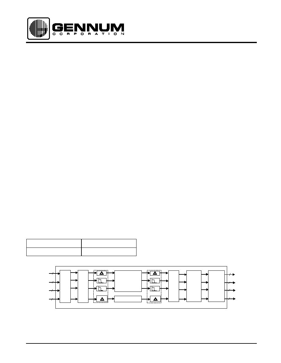
DEVICE OVERVIEW
The GF9105A is a drop in replacement for the GF9105 with
lower power and increased functionality. This increased
functionality gives the user the option of having HVF output
signals and the option of using a low frequency clock when
operating with non-multiplexed input and output data. The
GF9105A is a flexible VDSP engine capable of performing a
variety of format conversions. The flexible architecture of
the GF9105A also allows the user to perform a wide range
of DSP functions that require a general 3X3 multiplier
structure and/or high performance 1:2 interpolation and 2:1
decimation filters. Device configuration is selected by
writing configuration words through an asynchronous
parallel interface (HOST IF).
The GF9105A accepts either multiplexed or non-
multiplexed input data and may produce either multiplexed
or non-multiplexed output data. External H, V and F inputs
allow for the insertion of TRS words into multiplexed output
data streams.
All interpolation and decimation filtering required for ITU-R-
601 compliant 4:2:2:4 <-> 4:4:4:4 sample rate conversions
has been integrated into the GF9105A. In addition, all input
and output offset adjustments required for transparent
conversions between the Y/U/V and R/G/B color spaces
have been included within the GF9105A.
The color space converter within the GF9105A has 13 bit
multiplier coefficients, has 13 bit output resolution,
maintains full precision throughout the 3X3 calculation and
has a true unity gain by-pass mode. Sufficient resolution is
maintained within the color space converter to ensure that
truly transparent Y/U/V <-> R/G/B conversions may be
achieved. A user programmable output clipper allows the
GF9105A to output a variety of word lengths to meet
specific system requirements.
The GF9105A is packaged in a 160 pin MQFP package,
operates from a single +5V supply.
GENERAL FUNCTIONALITY OF GF9105A CORE
ORDERING INFORMATION
PART NUMBER
PACKAGE
GF9105ACQQ
160 Pin MQFP
OUTPUT
OFFSET
ADJUST
KEY
Y/G, CB/B, CR/R, KEY OR
Y/G, CB/B, CR/R, OR Y/G
KEY, CB/B, CR/R OR KEY
XX OR CR/R
XX OR CB/B
Y/G, CB/B, CR/R, KEY OR
Y/G, CB/B, CR/R, OR Y/G
CR/R OR XX
KEY OR KEY, CB/B, CR/R
CB/B OR XX
3 X 3
MATRIX
MULTIPLIER
KEY SCALER
DEMUX
4:4:4:4
OR
4:2:2:4
H_BLANK
AND
INPUT
OFFSET
ADJUST
Y/G
Y/G
Y/G
Y/G
Y/G
Y/G
Y/G
CB/B
CR/R
KEY
CB/B
CR/R
KEY
CB/B
CR/R
KEY
KEY
CB/B
CR/R
13
13
13
11
CB/B
CR/R
13
13
13
11
INT
INT
OUTPUT
CLIP
OUTPUT
MULTIPLEXER
KEY
KEY
CB/B
CR/R
CB/B
CR/R
DEC
DEC
MultiGEN
TM
GF9105A
Component Digital Transcoder

521 - 88 - 03
2
PIN DESCRIPTION
PIN NO.
SYMBOL
DESCRIPTION
11, 20, 51, 60, 80,
101, 121, 141, 150
V
DD
+5 V ±5% power supply.
4, 7, 10, 14, 21, 43,
52, 61, 63, 72, 81, 88,
96, 100, 105, 113,
120, 129, 138, 140,
149, 158
GND
Ground.
147, 148, 151-157,
159, 160, 1, 2
P1
12..0
Data Port No. 1: Depending on device configuration, P1
12..0
may operate as an input data port or
an output data port. Note: When HVF output is enabled H is always presented on P1
12
regardless
of the state of INPUT/
OUTPUT
.
131-137, 139, 142-
146
P2
12..0
Data Port No. 2: Depending on device configuration, P2
12..0
may operate as an input data port or
an output data port. Note: When HVF output is enabled V is always presented on P2
12
regardless
of the state of INPUT/
OUTPUT
.
115-119, 122-128,
130
P3
12..0
Data Port No. 3: Depending on device configuration, P3
12..0
may operate as an input data port or
an output data port. Note: When HVF output is enabled F is always presented on P3
12
regardless
of the state of INPUT/
OUTPUT
.
102-104, 106-112,
114
P4
10..0
Data Port No. 4: Depending on device configuration, P4
10..0
may operate as an input data port or
an output data port.
54, 53, 50-44, 42-39
P5
12..0
Data Port No. 5: Depending on device configuration, P5
12..0
may operate as an input data port or
an output data port.
70-64, 62, 59-55
P6
12..0
Data Port No. 6: Depending on device configuration, P6
12..0
may operate as an input data port or
an output data port.
86-82, 79-73, 71
P7
12..0
Data Port No. 7: Depending on device configuration, P7
12..0
may operate as an input data port or
an output data port.
99-97, 95-89, 87
P8
10..0
Data Port No. 8: Depending on device configuration, P8
10..0
may operate as an input data port or
an output data port.
22
SYNC_CB
Synchronization: Control signal input. SYNC_CB is used to synchronize the GF9105A to
the incoming data stream.
24
H_BLANK
Horizontal Blanking: Control signal input. H_BLANK is used to replace portions of the
input data with a user selectable set of blanking levels.
25
DP_EN
Data Port Enable: Control signal input. DP_EN is used to enable and disable data
ports P1 - P8.
17
H
Horizontal: Control signal input. H identifies the horizontal blanking interval for the
output multiplexer.
16
V
Vertical: Control signal input. V identifies the vertical blanking interval for the output
multiplexer.
18
F
Field: Control signal input. F is used to identify field information for the output
multiplexer.
26
CS
Chip Select: Host interface control signal input.
23
R/W
Read/Write: Host interface control signal input.
27-31
ADDR
4..0
Coefficient Address: Input port to identify which GF9105A device address shall be
written to/read from.
3, 5, 6, 8, 9, 12, 13,
15
COEFF_PORT
7..0
Coefficient Port: Host interface bi-directional data port for Color Space Converter
coefficients, KEY scaler coefficient and device configuration words.
19
CLK
System Clock: All timing information is relative to the rising edge of CLK.
32
TCK
JTAG Test Clock Input: Independent clock signal for JTAG.

521 - 88 - 03
3
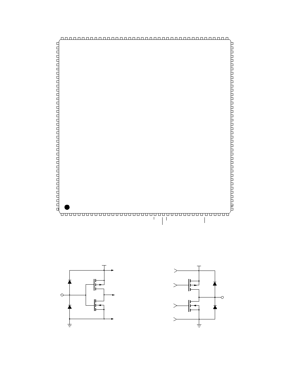
Fig. 1 GF9105A Data Pin Designations
33
TDI
JTAG Test Data Input: Serial input for JTAG test data.
34
TMS
JTAG Test Mode Select: Serial input for selecting JTAG test mode.
35
TRST
JTAG Test Reset: Connect to GND for normal operation.
36
TDO
JTAG Test Data Output: Serial output for JTAG test data.
37
TN_IN
Connect to V
DD
.
38
PTO
No Connect.
PIN DESCRIPTION
PIN NO.
SYMBOL
DESCRIPTION
147
148
151
152
153
154
155
156
157
159
160
1
2
131
132
133
134
135
136
137
139
142
143
144
145
146
115
116
117
118
119
122
123
124
125
126
127
128
130
102
103
104
106
107
108
109
110
111
112
114
27
28
29
30
31
3
5
6
8
9
12
13
15
54
53
50
49
48
47
46
45
44
42
41
40
39
70
69
68
67
66
65
64
62
59
58
57
56
55
86
85
84
83
82
79
78
77
76
75
74
73
71
99
98
97
95
94
93
92
91
90
89
87
GF9105A
22
24
25
17
16
18
26
23
19
32
33
34
35
36
37
38
P1
12
/H
OUT
P1
11
P1
10
P1
9
P1
8
P1
7
P1
6
P1
5
P1
4
P1
3
P1
2
P1
1
P1
0
P2
12
/V
OUT
P2
11
P2
10
P2
9
P2
8
P2
7
P2
6
P2
5
P2
4
P2
3
P2
2
P2
1
P2
0
P3
12
/F
OUT
P3
11
P3
10
P3
9
P3
8
P3
7
P3
6
P3
5
P3
4
P3
3
P3
2
P3
1
P3
0
P4
10
P4
9
P4
8
P4
7
P4
6
P4
5
P4
4
P4
3
P4
2
P4
1
P4
0
P8
10
P8
9
P8
8
P8
7
P8
6
P8
5
P8
4
P8
3
P8
2
P8
1
P8
0
P7
12
P7
11
P7
10
P7
9
P7
8
P7
7
P7
6
P7
5
P7
4
P7
3
P7
2
P7
1
P7
0
P6
12
P6
11
P6
10
P6
9
P6
8
P6
7
P6
6
P6
5
P6
4
P6
3
P6
2
P6
1
P6
0
P5
12
P5
11
P5
10
P5
9
P5
8
P5
7
P5
6
P5
5
P5
4
P5
3
P5
2
P5
1
P5
0
ADDR
4
ADDR
3
ADDR
2
ADDR
1
ADDR
0
COEFF_PORT
7
COEFF_PORT
6
COEFF_PORT
5
COEFF_PORT
4
COEFF_PORT
3
COEFF_PORT
2
COEFF_PORT
1
COEFF_PORT
0
SYNC_CB
H_BLANK
DP_EN
H
V
F
CS
R/W
CLK
TCK
TDI
TMS
TRST
TDO
TN_IN
PTO
P1
12..0
P2
12..0
P3
12..0
P4
10..0
P8
10..0
P7
12..0
P6
12..0
P5
12..0
V
DD
N.C
JT
AG
521 - 88 - 03
4
Fig. 2 GF9105A Pin Connections
Fig. 3a GF9105A Equivalent Input Circuit
Fig. 3b GF9105A Equivalent Output Circuit
V
DD
P3
7
P3
6
P3
5
P3
4
P3
3
P3
2
P3
1
GND
P3
0
P2
12
/V
OUT
P2
11
P2
10
P2
9
P2
8
P2
7
P2
6
GND
P2
5
GND
V
DD
P2
4
P2
3
P2
2
P2
1
P2
0
P1
12
/H
OUT
P1
11
GND
V
DD
P1
10
P1
9
P1
8
P1
7
P1
6
P1
5
P1
4
GND
P1
3
P1
2
GF9105A
TOP VIEW
80
79
78
77
76
75
74
73
72
71
70
69
68
67
66
65
64
63
62
61
60
59
58
57
56
55
54
53
52
51
50
49
48
47
46
45
44
43
42
41
121
122
123
124
125
126
127
128
129
130
131
132
133
134
135
136
137
138
139
140
141
142
143
144
145
146
147
148
149
150
151
152
153
154
155
156
157
158
159
160
1 2 3 4 5 6 7 8 9 10 11 12 13 14 15 16 17 18 19 20 21 22 23 24 25 26 27 28 29 30 31 32 33 34 35 36 37 38 39 40
99 98 97 96 95 94 93 92 91 90 89 88 87 86 85 84 83 82 81
V
DD
P7
7
P7
6
P7
5
P7
4
P7
3
P7
2
P7
1
GND
P7
0
P6
12
P6
11
P6
10
P6
9
P6
8
P6
7
P6
6
GND
P6
5
GND
V
DD
P6
4
P6
3
P6
2
P6
1
P6
0
P5
12
P5
11
GND
V
DD
P5
10
P5
9
P5
8
P5
7
P5
6
P5
5
P5
4
GND
P5
3
P5
2
P1
1
P1
0
COEFF
7
GND
COEFF
6
COEFF
5
GND
COEFF
4
COEFF
3
GND
V
DD
COEFF
2
COEFF
1
GND
COEFF
0
V
H
F
CLK
V
DD
GND
SYNC_CB
R/W
HBLANK
DP_EN
CS
ADDR
4
ADDR
3
ADDR
2
ADDR
1
ADDR
0
TCK
TDI
TMS
TRST
TDO
TN_IN
PT0
P5
0
P5
1
GND
P3
8
P3
9
P3
10
P3
11
P3
12
/F
OU
T
P4
0
GND
P4
1
P4
2
P4
3
P4
4
P4
5
P4
6
P4
7
GND
P4
8
P4
9
P4
10
V
DD
GND
P8
10
P8
9
P8
8
GND
P8
7
P8
6
P8
5
P8
4
P8
3
P8
2
P8
1
GND
P8
0
P7
12
P7
11
P7
10
P7
9
P7
8
GND
116 115 114 113 112 111 110 109 108 107 106 105 104 103 102 101 100
120 119 118 117
INPUT
n substrate
p WELL
GND
n
p
VDD
D1
D2
p+
n+
n substrate
p WELL
D1
D2
GND
OUTPUT
n
p
p+
n+
VDD
521 - 88 - 03
5
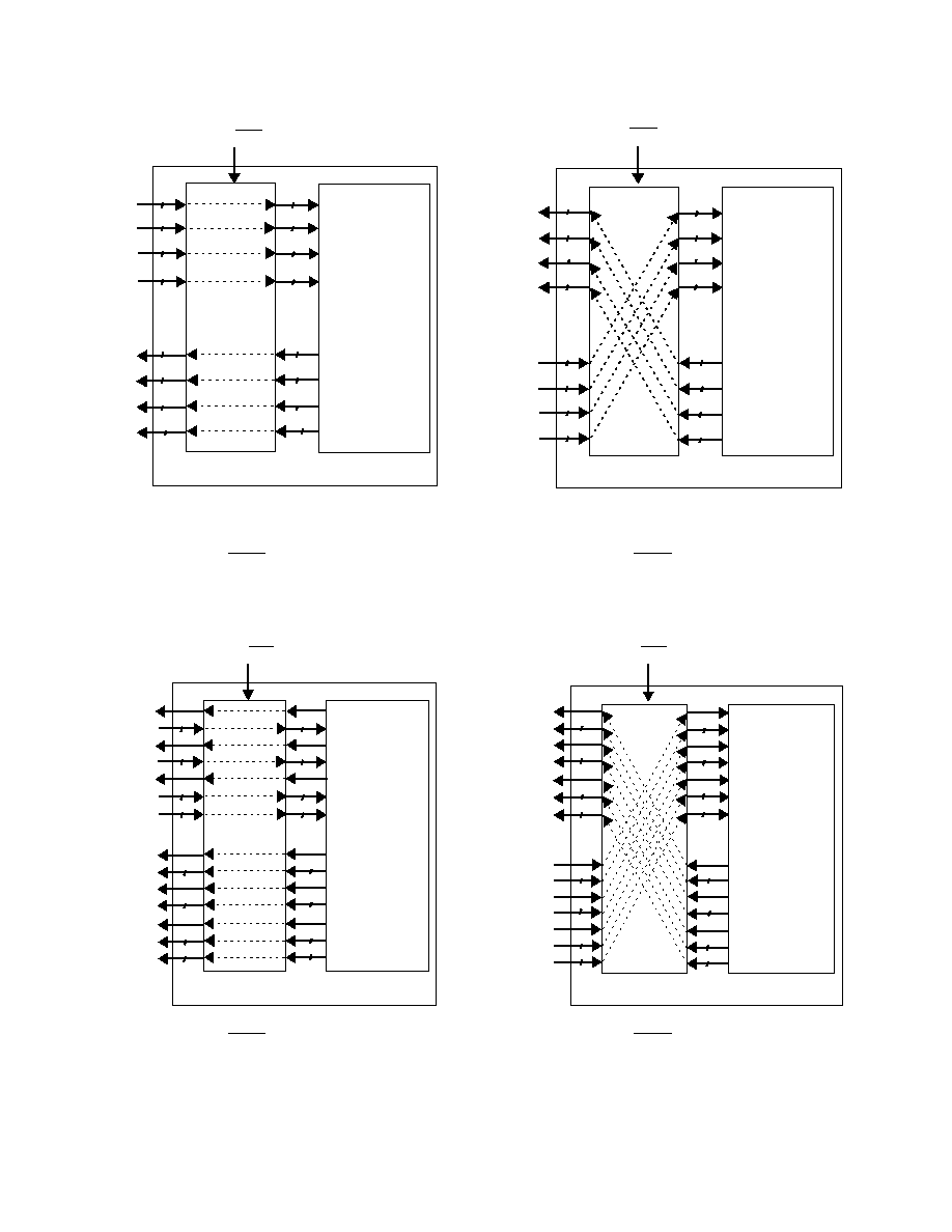
Fig. 4a Functional Block Diagram of GF9105A
(OUTPUT/INPUT = 0, HVF_OUT = 0)
Fig. 4c Functional Block Diagram of GF9105A
(OUTPUT/INPUT = 0, HVF_OUT = 1)
Fig. 4b Functional Block Diagram of GF9105A
(OUTPUT/INPUT = 1, HVF_OUT = 0)
Fig. 4d Functional Block Diagram of GF9105A
(OUTPUT/INPUT = 1, HVF_OUT = 1)
GF9105A SIGNAL
PROCESSING CORE
BI-DIRECTIONAL
DATA PORTS
PROCESSING
CORE OUTPUT
PROCESSING
CORE INPUT
OUTPUT/INPUT = 0
P1
12..0
P2
12..0
P3
12..0
P4
10..0
P5
12..0
P6
12..0
P7
12..0
P8
10..0
13
13
13
13
13
13
13
13
11
C1
C2
C3
C4
13
13
13
13
11
C5
C6
C7
C8
11
11
GF9105A SIGNAL
PROCESSING CORE
BI-DIRECTIONAL
DATA PORTS
PROCESSING
CORE OUTPUT
PROCESSING
CORE INPUT
OUTPUT/INPUT = 0
P1
12
/H
OUT
P1
11..0
P2
12
/V
OUT
P2
11..0
P3
12
/F
OUT
P3
11..0
P4
10..0
P5
12
P5
11..0
P6
12
P6
11..0
P7
12
P7
11..0
P8
10..0
12
12
12
11
}
}
}
}
C1
C2
C3
C4
12
12
12
11
}
}
}
}
C5
C6
C7
C8
12
12
12
11
12
12
12
11
P1
12..0
P2
12..0
P3
12..0
P4
10..0
PROCESSING
CORE OUTPUT
PROCESSING
CORE INPUT
P5
12..0
P6
12..0
P7
12..0
P8
10..0
OUTPUT/INPUT = 1
GF9105A SIGNAL
PROCESSING CORE
BI-DIRECTIONAL
DATA PORTS
C1
C2
C3
C4
C5
C6
C7
C8
13
13
13
13
13
13
13
13
13
13
13
13
11
11
11
11
P1
12
/H
OUT
P1
11..0
P2
12
/V
OUT
P2
11..0
P3
12
/F
OUT
P3
11..0
P4
10..0
PROCESSING
CORE OUTPUT
PROCESSING
CORE INPUT
P5
12
P5
11..0
P6
12
P6
11..0
P7
12
P7
11..0
P8
10..0
OUTPUT/INPUT = 1
GF9105A SIGNAL
PROCESSING CORE
BI-DIRECTIONAL
DATA PORTS
}
}
}
}
C1
C2
C3
C4
}
}
}
}
C5
C6
C7
C8
12
12
12
12
12
12
12
12
12
12
12
12
11
11
11
11