K73-24
___________________________________________________________________________________________
METALLIZED POLYESTER FILM CAPACITORS
:
.673633.010
,
,
.
73-17, 73-30,
73-34, 73-5.
:
.
Specifications:
.673633.010
Designed to operate in DC, AC and ripple
current circuits and in pulse mode.
Can be used instead of K73-17, K73-30,
K73-34, K73-5.
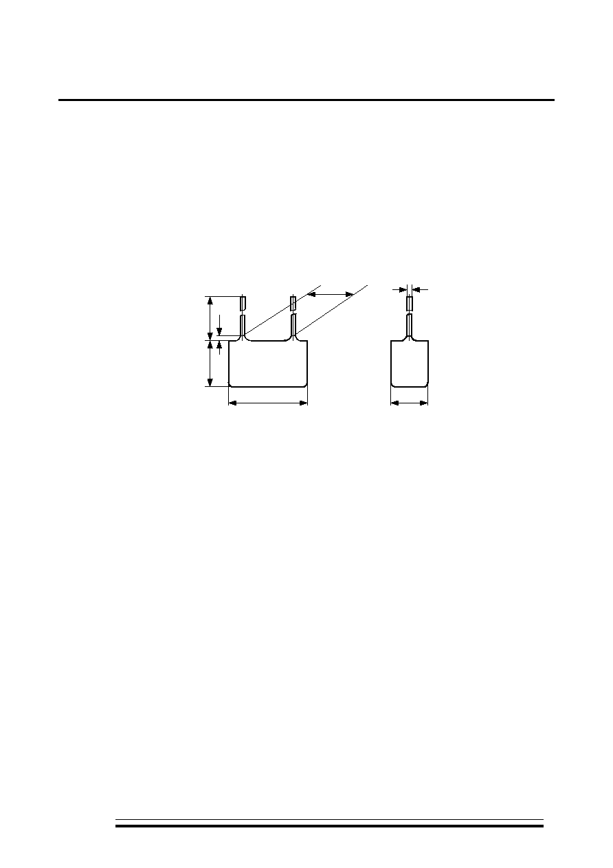
Design: dipped
.
20
+5
L max
H m
a
x
3 m
a
x
A
d
B max
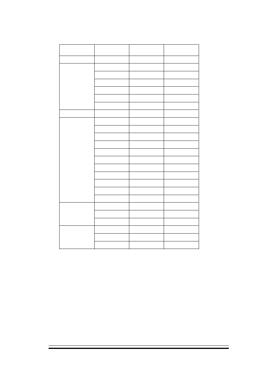
0,001 .... 6,8
Rated capacitance
0,001 .... 6,8 �F
(
-60
o
C ...+85
o
C)
63; 100; 160; 250;
400; 630
Rated voltage
(temperature range
-60
o
C...+85
o
C)
63; 100; 160; 250;
400; 630 V
�5; �10; �20 %
Capacitance tolerance
�5; �10; �20 %
f = 1
0,012
Dissipation factor at f = 1 kHz
0,012
C
0,33
3000 MO
Insulation
resistance
at Cr 0,33 �F
3000 MOhm
>0,33
1000 MO �
Time constant
at
r >0,33 �F
1000 MOhm��F
-60...+125
o
C
Operating
temperature
range
-60...+125
o
C
10%
Capacitance
change
within
positive temperature range
10%
15 000
Operating time
15 000 hours
10
Shelf
life
10
years
(93�3%
.
40�2
o
C, 10
)
Climatic categories
RH 93�3%,
40�2
o
C, 10 days
:
73-24 - 100 - 0,1
- � 20% -
7,5
( �
)
Ordering example:
Capacitor K73-24 - 100 V - 0,1 �F - � 20% -
7,5 mm ( � lead spacing)
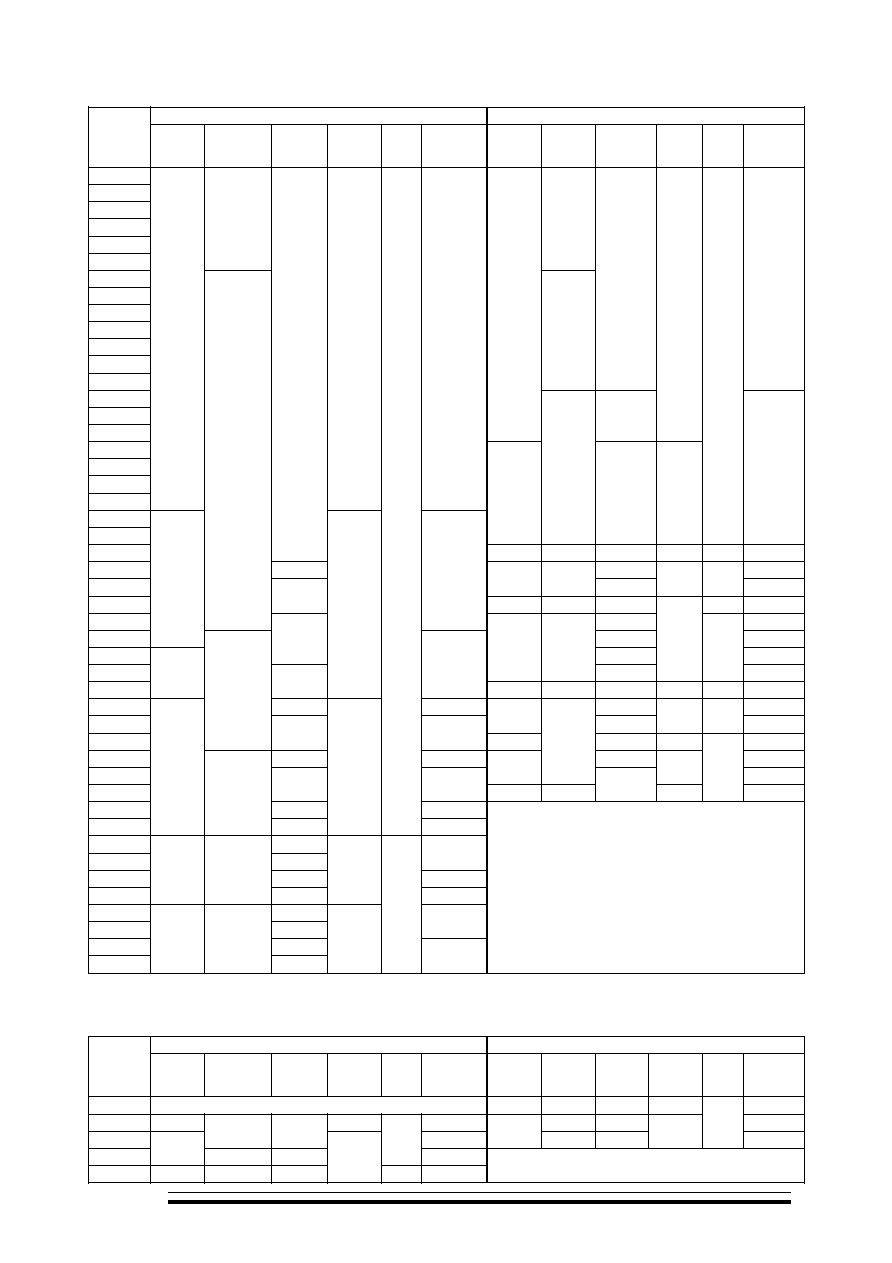
U
=400 / U
r
=400 V
U
=630 / U
r
=630 V
,
C
r
, �F
L
max
,
mm
H
max
,
mm
B
max
,
mm
A,
mm
d,
mm
,
Mass, g
max
L
max
,
mm
H
max
,
mm
B
max
,
mm
A,
mm
d,
mm
,
Mass,g
max
0.010 10.5
2.0
0.015
13
6 0.6
3.0
0.022 10.5
2.0
13
15 7
10
3.4
0.033 13
6 0.6
3.0 13
6
3.6
0.047
13
15 7
10
3.4 14
7
4.0
0.068 13
5
3.6
18
15 8
15
4.7
0.10 14
6
4.0 18
7
5.8
0.15
18
15 8
15
4.7 19
8.5
6.0
0.22 18
7
5.8
23
21 10.5
0.8
6.8
0.33 19
8.5
6.0 24
11.5
8.3
0.47
23
21 10
0.8
6.8
25
25 15.5
20
1.0
12.0
0.68 24
11
8.3
1.0
24
27 14
20
1.0
12.0
U
t
U
t
%
-60
0
20
40
60
80
t
o
100
125
100
75
50
25
120
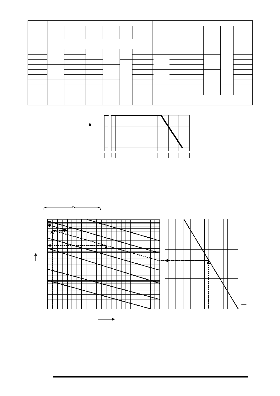
U
Permissible voltage
U
t
as a function of
ambient temperature
U
f
f
Permissible amplitude of AC sinusoidal voltage or amplitude of AC sinusoidal component of ripple voltage
U
f
as a function of frequency f
2
10
10
-1
0
10
2
10
10
-3
1
U
f
U
t
4
6
8
2
4
6
8
2
4
6
8
%
10
-1
1,5
10
10
10
10
1
2
0
5
f
10
3
10
4
10
-2
2,2 3,3 4,7 6,8
1,5 2,2 3,3 4,7 6,8
1,5 2,2 3,3 4,7 6,8
1,5 2,2 3,3 4,7 6,8
2
5
2
5
2
5
2
5
2
5
10
6
C
630
400
250
160
100
63
U
,
U
f
:
: f=1�10
4
, U
t
=U
=630 ,
=0,1
: U
f
=13%
U
=82
: f =1�10
4
, U
t
=U
=250 ,
=1500
: U
f
=64,5%
U
=161
Example of calculation of U
f
:
Given: f =1�10
4
Hz , U
t
=U
r
=630 V,
r
=0,1 �F
Finding: U
f
=13% of U
r
=82 V
Given: f =1�10
4
Hz , U
t
=U
r
=250 V,
r
=1500 pF
Finding: U
f
=64,5% of U
r
=161 V

U
F ,
,
,
Permissible peak-to-peak pulse voltage U as a function of pulse repetition frequency F , minimal temporal
sector ,corresponding pulse leading edge slope
or pulse trailing edge slope and rated capacitance
r
630
400
250
160
100
63
U
,
2
10
10
10
10
U
U
t
4
6
8
2
4
6
8
2
4
6
8
%
-1
0
2
1
10
-3
10
-1
1,5
10
10
10
10
1
2
0
5
F
10
3
10
4
10
-2
2,2 3,3 4,7 6,8
1,5 2,2 3,3 4,7 6,8
1,5 2,2 3,3 4,7 6,8
1,5 2,2 3,3 4,7 6,8
2
5
2
5
2
5
2
5
2
5
10
6
C
U
u
u =
10 C
-4
u =
10 C
u =
10 C
-5
-6
u
c
U :
:
F =2�10
4
,
=10
-6
c,
U
t
=U
=630 ,
=0,22
:
U =6%
U
=37,8
:
F =2�10
4
,
=10
-6
c,
U
t
=U
=63 ,
=0,01
:
U =40%
U
=25,2
Example of calculation of U :
Given:
F =2�10
4
Hz ,
=10
-6
s,
U
t
=U
r
=630 V,
r
=0,22 �F
Finding:
U =6% f U
r
=37,8 V
Given:
F =2�10
4
Hz ,
=10
-6
s,
U
t
=U
r
=63 V,
r
=0,01 �F
Finding:
U =40% f U
r
=25,2 V