 | –≠–ª–µ–∫—Ç—Ä–æ–Ω–Ω—ã–π –∫–æ–º–ø–æ–Ω–µ–Ω—Ç: –ö75-63 | –°–∫–∞—á–∞—Ç—å:  PDF PDF  ZIP ZIP |
75-63
____________________________________________________________________________
PAPER ≠ FILM CAPACITORS WITH FOIL ELECTRODES
,
,
.
75-15, 75-22, 75-29,
75-47.
:
.
Designed to operate in DC, AC and ripple
current circuits and in pulse mode.
Can be used instead of K75-15, K75-22, K75-
29, K75-47.
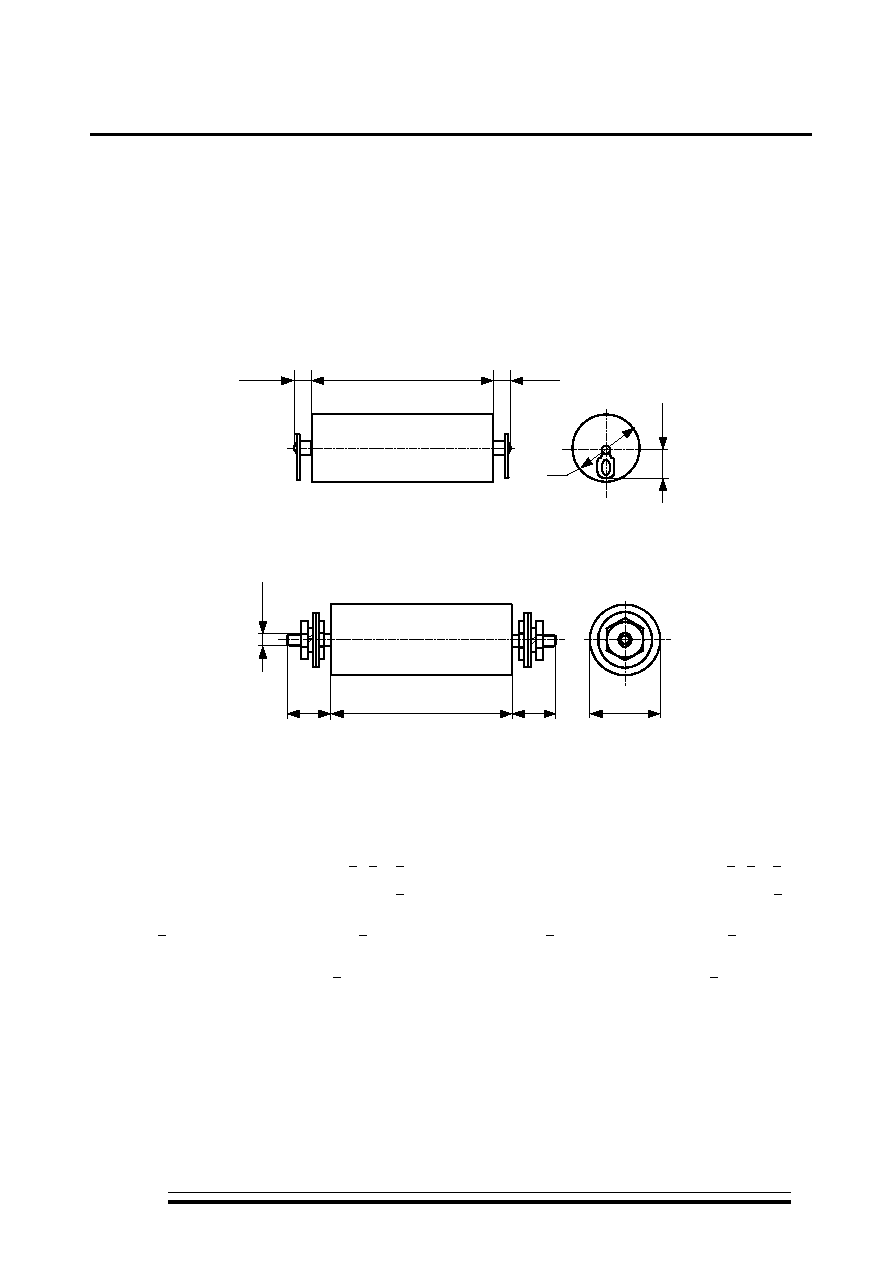
Design:
cylindrical housing made of
polymeric materials. Axial terminals.
L
12
max
12
max
12±
1
D
" "
Design
" "
L
22
max
22
max
M
6
-6
g
D
" "
Design
"b"
0,01...22
Rated capacitance
0.01...22 F
2,5...40
Rated voltage
2.5...40 kV
+5; +10; +20%
Capacitance tolerance
+5; +10; +20%
f = 1
<0,01
Dissipation factor at f=1 kHz
<0.01
r < 0,22
> 1200
Insulation
resistance
at r < 0.22 µF
> 1200 MOhm
r > 0,22
> 4000
.
Time
constant
at r > 0.22 µF
> 4000 MOhm.µF
-60...+85
o
C
Operating
temperature
range
-60...+85
o
C
K75-63 (+85
o
C)
K75-63 (+70
o
C)
2000
3000
Operating time
K75-63 (+85
o
C)
K75-63 (+70
o
C)
2000 hours
3000 hours
20
Shelf life
20 years
:
75-63 ≠ 4
≠ 0,1
- ± 10%
Ordering example:
Capacitor K75-63 ≠ 4 kV ≠ 0.1 µF - ± 10%
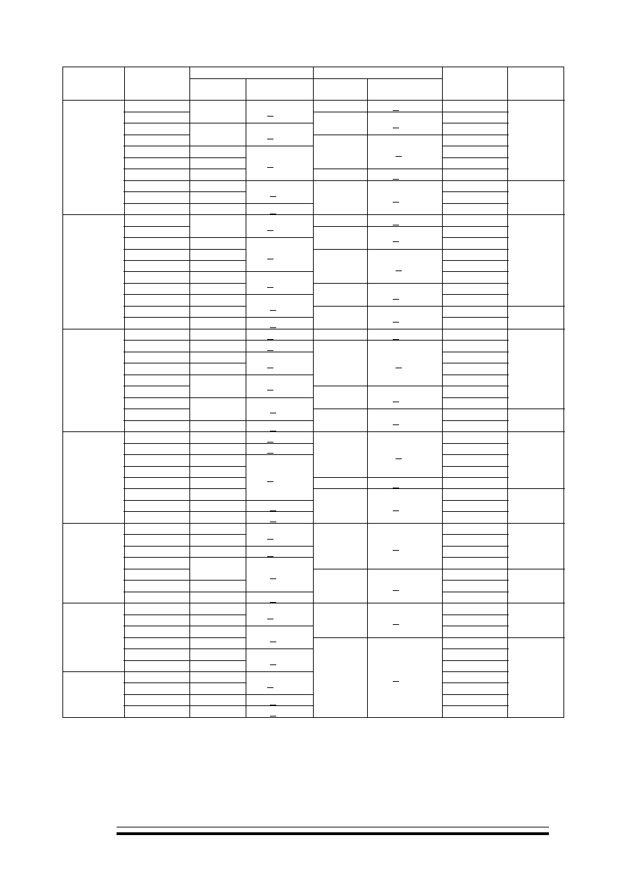
D, mm
L, mm
Ur, V
Cr, µF
Rated
value
Limit
discrepancy
Rated
value
Limit
discrepancy
Mass, g
max
Design
0.022
30
+1.65
20
0.047
16
+1.35
30
0.10
48
+1.95
50
0.22
22
+1.65
60
0.47
32
160
1.0
42
90
+2.7
230
2.2
50
+1.95
140
+3.15 500
a (a)
4.7
56
1200
10.0
75
+2.3
2100
2.5
22.0
95
+2.7
280
+4.05
3300
(b)
0.010
30
+1.65
20
0.022
16
+1.35
30
0.047
22
48
+1.95
50
0.10
20
80
0.22
28
+1.65
120
0.47
40
90
+2.7
230
1.0
42
+1.95
350
2.2
60
140
+3.15
700
a (a)
4.7
63
+2.3
1500
4.0
10.0
95
+2.7
280
+4.05
3300
(b)
0.010
20
+1.65
48
+1.95 40
0.022
16
+1.35
50
0.047
22
80
0.10
30
+1.65
140
0.22
90
+2.7
250
0.47
45
+1.95
400
1.0
140
+3.15
800
a (a)
2.2
63
+2.3
1500
6.3
4.7
90
+2.7
280
+4.05
2900
(b)
0.010
16
+1.35
50
0.022
24
+1.65
90
0.047
32
160
0.10
45
90
+2.7
250
0.22
48
140
+3.15 450
a (a)
0.47
50
+1.95
1000
1.0
67
+2.3
1700
10
2.2
85
+2.7
280
+4.05
2500
(b)
0.010
20
90
0.022
28
+1.65
190
0.047
40
+1.95 300
0.10
140 +3.15
650
a (a)
0.22
56
1200
0.47
75
+2.3
2100
16
1.0
95
+2.7
280
+4.05
3300
(b)
0.010
32
230
0.022
45
+1.95
400
0.047
63
140 +3.15
800
a (a)
0.10
60
+2.3
1400
0.22
85
2500
25
0.47
105
+2.7
4100
0.010
40
650
0.022
50
+1.95
1000
0.047 67 +2.3
1700
40
0.1 85 +2.7
280
+4.05
2500
(b)
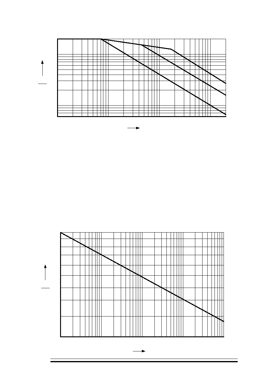
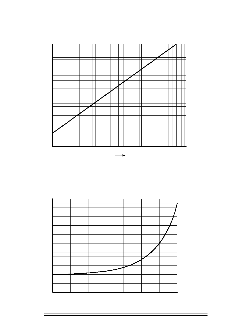
U
m
f
Permissible amplitude of AC sinusoidal component of ripple voltage U
m
as a function of frequency f
2
1
0.6
20
%
10
10
2
10
3
Hz
f
U
m
U
r
10
4
2 10
4
.
10
1)
16; 25; 40
;
2,5
(2,2; 4,7; 10; 22
);
4
(2,2; 4,7; 10
);
6,3
(1; 2,2; 4,7
);
10
(0,22; 0,47; 1,0; 2,2
);
2)
2,5
(0,47; 1,0
);
4
(0,1; 0,22; 0,47; 1,0
);
6,3
(0,047; 0,10; 0,22; 0,47
);
10
(0,022; 0,047; 0,10
);
3)
2,5
(0,022; 0,047; 0,10; 0,22
);
4
(0,01; 0,022; 0,047
);
6,3
(0,01; 0,022
);
10
(0,01
).
1)
16; 25; 40 kV;
2.5 kV (2.2; 4.7; 10; 22 F);
4 kV (2.2; 4.7; 10 F);
6.3 kV (1; 2.2; 4.7 F);
10 kV (0.22; 0.47; 1.0; 2.2 F);
2)
2.5 kV (0.47; 1.0 F);
4 kV (0.1; 0.22; 0.47; 1.0 F);
6.3 kV (0.047; 0.10; 0.22; 0.47 F);
10 kV (0.022; 0.047; 0.10 F);
3)
2.5 kV (0.022; 0.047; 0.10; 0.22 F);
4 kV (0.01; 0.022; 0.047 F);
6.3 kV (0.01; 0.022 F);
10 kV (0.01 F).
U
,
.
Peak-to-peak pulse voltage U
p
must not exceed the values defined from the Figure below.
U
F
Permissible amplitude of peak-to-peak pulse voltage U
p
as a function of pulse repetition rate F
p
65
60
55
50
45
40
35
30
25
20
%
0.1
1
10
10
2
10
3
Hz
F
p
U
p
U
r
U
I
F
,
:
U I F
≠
,
;
-
,
,
;
-
,
,
:
- 0,8 ≠
;
- 1,0 -
(
)
20%;
-
,
, -
;
I ≠
,
;
F -
.
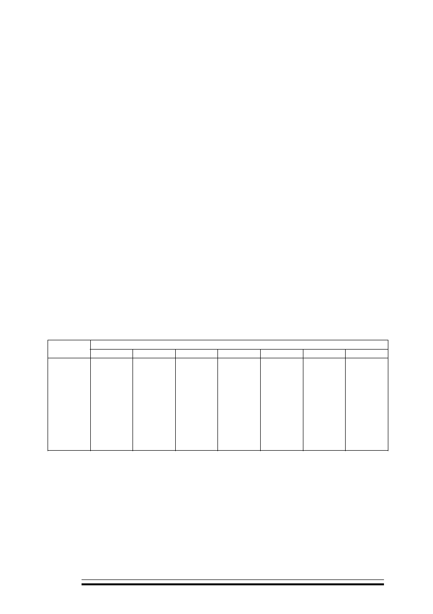
Permissible combinations of U
p
I
p
F
p
must not exceed the values calculated from the following
formula:
U
p
I
p
F
p
P,
where
P - a parameter specifying loss power tolerance at a natural convective heat transfer along the lateral
surface that is given in the table.
- a coefficient that allows for the capacitor discharge time. It depends on the duration of the discharge
current pulse and is determined from the Figure below
- a coefficient that allows for the discharge mode of the capacitor and is equal to:
- 0.8 ≠ for the aperiodic and oscillatory modes with one half-wave of the current;
- 1.0 - for the pulse mode with the discharge depths (voltage derating ratio) up to 20%;
- values measured from the figure for oscillatory damping mode of discharge
I
p
≠ discharge current amplitude of the capacitor
F
p
- pulse repetition rate
P 10
-6
, VA/c, at U
r
, kV
Cr, µF
2.5 4.7 6.3 10 16 25 40
0.010
0.022
0.047
0.10
0.22
0.47
1.0
2.2
4.7
10
22
-
4.5
7
10
16
22
27
46
60
70
140
4.5
7
10
15
20
25
40
48
70
75
-
9
12
16
21
30
40
50
70
75
-
-
12
17
22
30
42
60
70
75
-
-
-
17
25
36
45
60
75
140
-
-
-
-
32
40
50
65
75
150
-
-
-
-
-
55
60
75
130
-
-
-
-
-
-
-
(
0,5 I )
as a function of the discharge current pulse duration
p
(at a level of 0.5 I
p
)
20
10
1
0.1
0.1
1
10
100
p
s
U
/U
as a function of U
rev
/U
p
for the oscillatory damped mode of discharge
4
1
2
3
0
0.2
0.3
0.4
0.5
0.6
0.7
0.8
0.9
U
rev
U
p