K78-12
__________________________________________________________________________
HIGN-FREQUENCY POLYPROPYLENE FILM CAPACITORS
:
. 673635.006
,
,
.
:
,
.
" ": D 36 mm.
" ":
U
= 2000 , C
= 2,2
.
Specification:
. 673635.006
Designed to operate in DC, AC and ripple
current circuits and in pulse mode.
Design: wrapped with adhesive tape; capacitor
ends sealed with
compound.
Design " ": D 36 mm.
Design " ": for Ur = 2000 V, Cr = 2,2 µF
.
" "
Design " ":
" "
Design " ":
" "
Design " ":
" "
Design " ":
L max
D max
d
d
25
+5
25
+5
L max
L max
L max
D max
D max
D max
1,5
20
+
2
,6
20
+2,6
20
+
2
,6
20
+
2
,6
20
+5
20
20
+5
4
9
6,5
d
0,001 .... 15
Rated capacitance
0,001 .... 15 µF
500, 1000, 1600,
2000
Rated voltage
500, 1000, 1600,
2000 V
±5, ±10; ±20 %
Capacitance tolerance
±5, ±10; ±20 %
f=1
0,0015
Dissipation factor at f=1 kHz
0,0015
C
0,33
50 000 Mo
Insulation
resistance
at Cr 0,33 µF
50 000 MOhm
C
> 0,33
15 000
.
Time constant
at Cr > 0,33 µF
15 000 MOhm. µF
-60...+85
o
C
Operating
temperature
range
-60...+85
o
C
(-500... 0).10
-
6
-1
TC
(-500 ... 0) ppm/
o
C
10
000
Operating time
10 000 hours
12
Shelf
life
12
years
(93±3%
.
40±2
o
C, 21
)
Climatic categories
RH 93±3%, 40±2
o
C,
21 days
:
78-12 -1600 - 0,1
- ± 10%
Ordering example:
Capacitor K78-12 -1600 V - 0,1 µF - ± 10%
U
f
f
Permissible amplitude of AC sinusoidal voltage or amplitude AC sinusoidal component of ripple voltage U
f
as a function of frequency f
1
10
100
1000
f
10
1,5
4,7
10
0
2,2
2,2
4,7
10
-1
2,2
4,7
-2
10
2,2
4,7
-3
10
0,06
0,08
0,1
0,2
0,4
0,8
1,0
2
4
8
10
40
20
80
100
C
U
U
f
%
2
5
2
5
2
5
:
U
f
U
U
f
750 B
U
= 1000 B; 1600 B
U
f
1100 B
U
= 2000 B
Limits:
U
f
U
r
U
f
750 V for U
r
= 1000 V; 1600 V
U
f
1100 V for U
r
= 2000 V
U
f
:
:
f = 10
, U
= 1000 , C
= 1
:
U
f
= 40%
U
=400
Example of calculation of U
f
:
Given:
f = 10 kHz , U
r
= 1000 V, C
r
= 1 µF
Finding:
U
f
= 40% of U
r
= 400 V

U
F ,
,
,
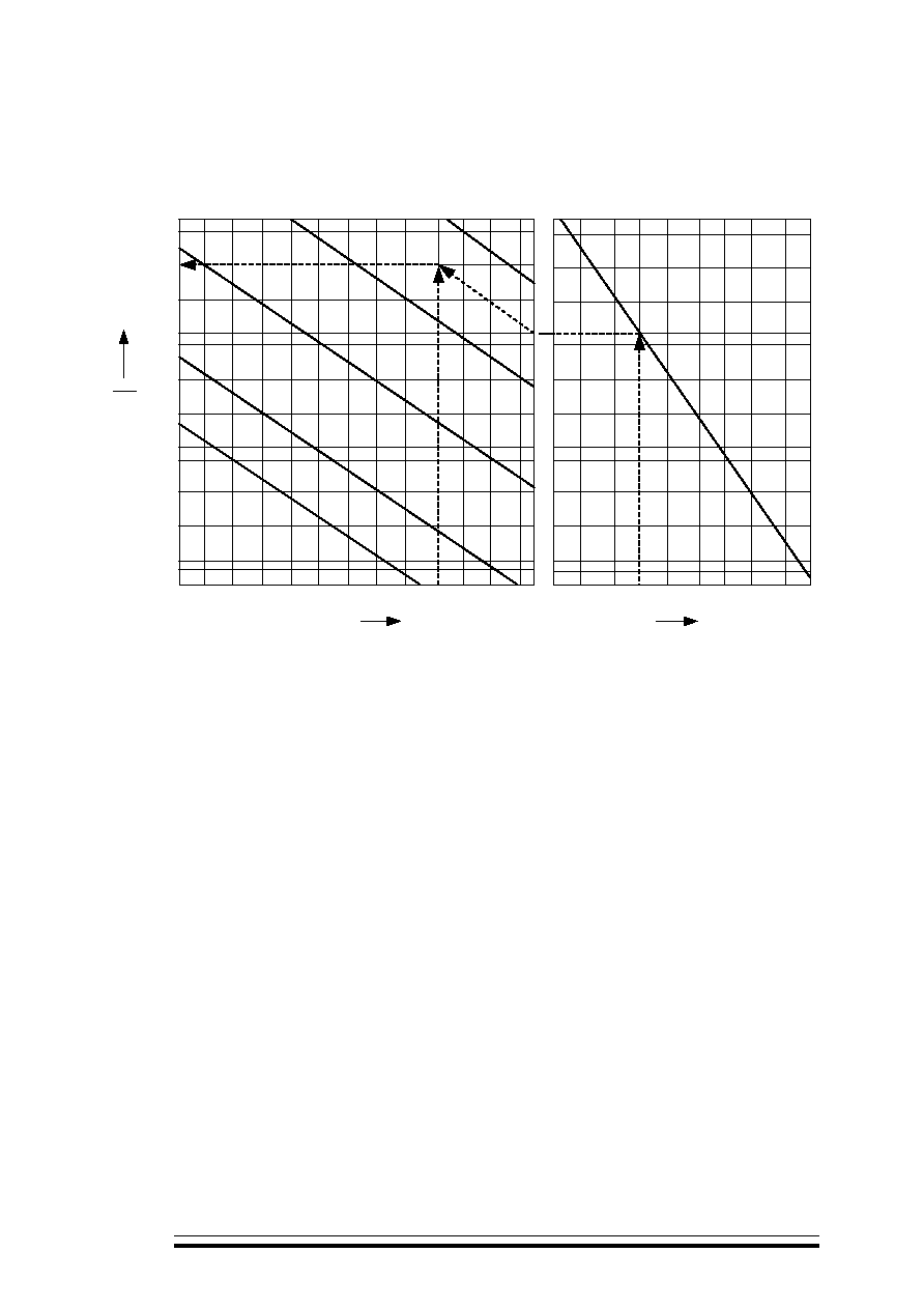
Permissible peak-to-peak pulse voltage U as a function of pulse repetition frequency F , minimal
temporal sector , corresponding pulse leading edge slope
or pulse trailing edge slope and rated
capacitance
r
2
10
10
10
10
U
4
6
8
2
4
6
8
1
4
6
8
%
-1
0
2
10
-1
10
10
10
1
2
0
10
3
10
-2
2,2
4,7
2,2
4,7
2,2
4,7
1,5
5
C
U
u
u =
10 C
-5
u =
10 C
u =
10 C
-6
-7
u
c
U
t
F
u
10
1
10
0
4,7
2
U
u
2
5
2
5
2
10
-3
2,2
:
U
U
U
1500 B
U
= 1600 B
Limits:
U
U
r
U
1500 V for U
r
= 1600 V
U :
:
F = 50
,
= 1
c,
U
= 1000 , C
= 0,47
:
U = 11%
U
= 110
Example of calculation of U :
Given:
F = 50 kHz ,
= 1 µs,
U
r
= 1000 V, C
r
= 0,47 µF
Finding:
U = 11% of U
r
= 110 V