Notes:
(1) Measured at 1.0MHz and applied reverse voltage of 4.0 VDC
(2) Thermal resistance junction to ambient
Symbols
1G1
1G2
1G3
1G4
1G5
1G6
1G7
Units
Maximum repetitive peak reverse voltage
V
RRM
50
100
200
400
600
800
1000
Volts
Maximum RMS voltage
V
RMS
35
70
140
280
420
560
700
Volts
Maximum DC blocking voltage
V
DC
50
100
200
400
600
800
1000
Volts
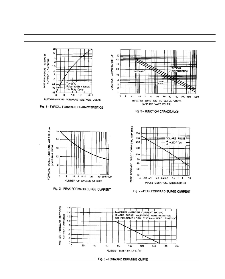
Maximum average forward rectified current
0.375" (9.5mm) lead length at T
A
=75
I
(AV)
1.0
Amp
Peak forward surge current, I
FM
(surge):
8.3mS single half sine-wave superimposed
on rated load (MIL-STD-750D 4066 method)
I
FSM
30.0
Amps
Maximum forward voltage at 1.0A
V
F
1.1
Volts
Maximum DC reverse current T
A
=25
at rated DC blocking voltage T
A
=100
I
R
5.0
100.0
A
Typical junction capacitance (Note 1)
C
J
15.0
F
Typical thermal resistance (Note 2)
R
JA
50.0
/W
Operating and storage temperature range
T
J
, T
STG
-55 to +150
Features
Mechanical Data
1G1 THRU 1G7
MINIATURE GLASS PASSIVATED JUNCTION RECTIFIER
Reverse Voltage -
50 to 1000 Volts
Forward Current -
1.0 Ampere
Plastic package has Underwriters Laboratory
Flammability Classification 94V-0 utilizing
Flame retardant epoxy molding compound
Glass passivated junction version of 1G1
thru 1G7 in R-1 package
1.0 ampere operation at T
A
=75 with no
thermal runaway
Case: Molded plastic, R-1
Terminals: Axial leads, solderable
per MIL-STD-202, method 208
Polarity: Color band denotes cathode
Mounting Position: Any
Weight: 0.007 ounce, 0.205 gram
DIMENSIONS
DIM
inches
mm
Note
Min.
Max.
Min.
Max.
A
0.114
0.138
2.9
3.5
B
0.095
0.099
2.42
2.51
C
0.020
0.024
0.5
0.6
D
1.000
-
25.40
-
Maximum Ratings and Electrical Characteristics
1
Ratings at 25 ambient temperature unless otherwise specified.
Single phase, half wave, 60Hz, resistive or inductive load.