
SSDK34-C7557-V2.00-01
99/09
C7557
MCD Controller
Application Software
Instruction manual

Notes
This instruction manual explains how to use the C7557 MCD (Multichannel Detector) Controller
Application Software, but does not provide a detailed description of the C7557 MCD Controller.
Please refer to the instruction manual supplied with the C7557.
The contents of this software instruction manual are subject to change without prior notice due
to product improvement and other factors.
Table of Contents
1. Software Overview
............................................................... 2
2. Measurement Condition Setup
............................................. 3
3. Data Display Window
........................................................... 7
4. Menu Description
............................................................... 20

2
1. Software Overview
This software contains the following files which are required to start this software and control the C7557
MCD controller.
File Name
Description
C7557APL.EXE
Execution file for this software
SENSOR.TBL
Sensor information list file
MCDMAIN.DLL
Interface DLL file for this software and an MCD controller
MCDCONT.DLL
DLL file for controlling an MCD controller
WNASPI132.DLL
DLL file for controlling a SCSI interface
When this software starts up, the main window as shown below first appears on the screen.
Figure 1: Software main window
This main window consists of three areas.
Measurement condition setup area
Data display area
Menu bar
The subsequent pages provide a description of each area.

3
2. Measurement Condition Setup
Figure 2: Measurement condition setup screen
The measurement condition setup area is divided into the following 5 boxes.
Detector Head Control box
Start Interval (ms)
Set an exposure time for the sensor.
It is not possible to set an exposure time which is shorter than the minimum time for each sensor.
True Integration Time (ms)
Shows an actual integration time.
Amp Gain
Select the output amplifier gain.
4
Cooling ON
Select this option to perform temperature control of the sensor head.
A check mark appears on the left when this option is selected indicating that the sensor
temperature is currently controlled. Each time you click this option, temperature control is switched
on and off.
Sensor head operation mode
Select here the sensor head operation mode.
Mode
Description
Line Scanning Mode
1D readout mode (InGaAs image sensor)
Line Binning Mode
1D readout mode (compatible with CCD)
Area Scanning Mode
2D readout mode (compatible with CCD)
Measurement Control box
Measurement mode
Select the measurement mode between the following two modes.
Mode
Description
Single Shot Measurement
Acquires one shot of data.
Continuous Measurement
Acquires data continuously.
Continuous Number
Set the measurement count in the continuous measurement mode.
When this parameter is set to "0", measurement continues until the Stop is clicked.
Number of Scans
Set the number of scans to acquire data in the continuous measurement mode.
Averaging ON
Select this option to take an average of data obtained in the continuous measurement mode.
A check mark appears on the left when this option is selected indicating that data is currently
averaged. Each time clicking this option, averaging is switched on and off.
Averaging Mode
Select the averaging mode.
Mode
Description
Hardware Averaging
Acquires data and then performs averaging.
Software Averaging
Performs averaging each time data is acquired.
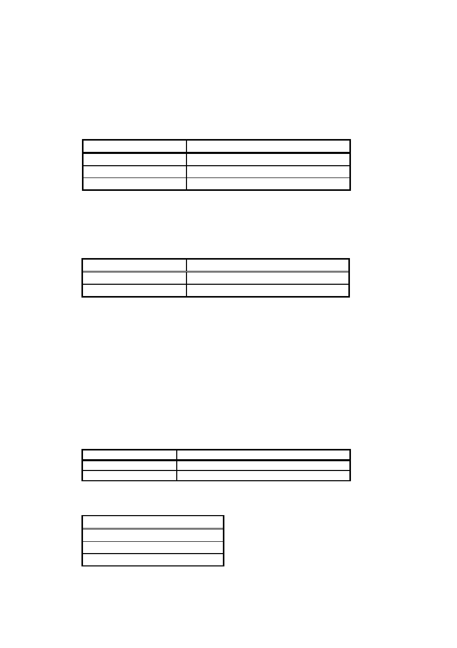
Acquired Mode
Select the type of data to be acquired.
Mode
Sample Acquired
Reference Acquired
Dark Acquired