 | –≠–ª–µ–∫—Ç—Ä–æ–Ω–Ω—ã–π –∫–æ–º–ø–æ–Ω–µ–Ω—Ç: L2783 | –°–∫–∞—á–∞—Ç—å:  PDF PDF  ZIP ZIP |

The Hamamatsu laser galvatron is an opto-galvanic sensor
taking advantage of the resonance phenomenon between the
discharge plasma and incident laser.
A laser is entered into a discharge plasma produced at the
see-through cathode of the galvatron. When the wavelength of
the laser is resonant with the absorbed wavelengths of atoms
and molecules inside the discharge plasma, the electrical
properties of the discharge plasma are altered. This
phenomenon is known as the opto-galvanic effect. The
galvatron L2783 series make use of an opto-galvanic signal
obtained by changes in the electrical properties, and it can be
used to calibrate the absolute wavelength of the incident laser
and stabilize the laser frequency.
Since the L2783 series are constructed with see-through
cathodes made with 63 elements and 6 types of filler gases,
any type of a galvatron can be selected to obtain the absorbed
wavelength of a discharge plasma which can resonate with the
wavelengths of the laser used.
OPTO-GALVANIC SENSOR
LASER GALVATRON
Æ
(SEE-THROUGH HOLLOW CATHODE LAMP)
L2783 SERIES
Laser Sensor Using The Opto-Galvanic Effect
Highly Stable Output, See-Through Cathode
Optimality for Laser Wavelength Calibration and Laser Frequency Stabilization
Information furnished by HAMAMATSU is believed to be reliable. However, no responsibility is assumed for possible inaccuracies or omissions. Specifications are
subject to change without notice. No patent rights are granted to any of the circuits described herein. ©2001 Hamamatsu Photonics K.K
Subject to local technical requirements and regulations, availability of products included in this promotional material may vary. Please consult with our sales office.
FEATURES
GHigh Stability Opto-Galvanic Signal
With respect to the incident laser beam, a highly stable, sensitive opto-
galvanic signal can be obtained.
GSee-Through Cathode
Since a see-through cathode is used, a laser does not strike the cath-
ode surface. So, it produces no photoelectric noise.
GBrewster Window with No Laser Interference
The input and output windows are inclined 10
∞ each so that no laser re-
flects to be returned. So, there are no laser interference results.
GSelective Cathode Materials and Filler Gases
This series can be selected from 63 elements and Ne (our standard
gas), other of filler gases in order to suit your applications. As for the
other filler gases, please contact us.
APPLICATIONS
GCalibration of dye laser absolute wavelength
GStabilization of laser frequency
GOptical communications
GMeasuring instrument standard

LASER GALVATRON
Æ
(SEE-THROUGH HOLLOW CATHODE LAMP)
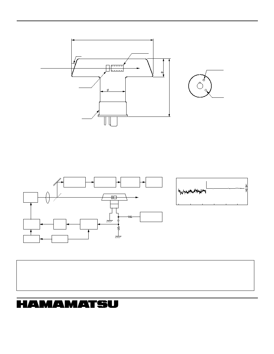
CONSTRUCTION
Galvatrons are constructed with a see-through cathode, a ring-
shaped anode mounted inside a T-shaped, Brewster glass bulb
and a filler gas. The construction is shown in Figure 1.
OPERATION CIRCUIT
To obtain an opto-galvanic signal using a galvatron, a driving
circuit for the laser galvatron to produce a discharge plasma
and a signal output circuit are required.
Figure 3 shows a schematic diagram for the driving and signal
circuits (operation circuit as a whole) of the galvatron.
PRINCIPLE OF OPERATION
When operating the galvatron, a discharge plasma is generated
at the hole of the see-through cathode. When a laser enters the
hole, and then the absorbed wavelengths of atoms and
molecules inside the discharge plasma resonate with the
wavelength of the incident laser, the electronic properties of the
discharge plasma are altered, such as discharge voltage,
discharge current and impedance, by which an opto-galvanic
signal is obtained. Figure 2 shows the relationship between the
absorbed wavelength and the opto-galvanic signal. When the
laser wavelength and the absorbed wavelength are perfectly
resonant (C), the strongest opto-galvanic signal is obtained.
When they are not resonant (B, D), the opto-galvanic signal
becomes much smaller than in the above case.
The absorbed spectral widths of atoms and molecules of the
cathode material and filler gas are sharper than that of the
incident laser beam. Since the absorbed wavelength is
generally known, observing the opto-galvanic signal obtained
here allows you to measure the peak absolute wavelength of
the incident laser with high precision.
In addition, since the opto-galvanic signal is obtained in
response to changes in the output and the frequency of the
incident laser, galvatrons can also be applied to stabilize the
incident laser.
To operate the galvatron properly, care should be taken to the
following precautions and assemble the operation circuit.
Using the operation circuit of Figure 3, the opto-galvanic signal
obtained when a dye laser beam excited by excimer laser pas-
ses through the galvatron is shown in Figure 4. The relationship
between the incident laser power and the opto-galvanic signal is
shown in Figure 5.
∑ A high voltage DC power supply with an output voltage of from 0 to
1000 V dc, an output current more than 20 mA and a ripple voltage
less than 0.5 mV should be used.
∑ A resistor R is used as a limit resistor for the discharge current and
a signal detection resistor.
For this reason, when using with a constant voltage power supply,
the resistor should be always added in to stabilize the galvatron in
operation.
∑ The capacitor C is used to obtain only AC current.
When using our recommended 0.047
µF capacitor, the signal
change from about 80 Hz to several KHz can be observed.
In addition, when changing the value to 0.5
µF, the lower frequency
than 80 Hz can be observed.
∑ In the measurements of opto-galvanic signals, it is difficult to obtain
the exact signal if there is an external electromagnetic induction.
For this reason, the circuit portion surrounded by dashed lines
shown in Figure 3 should be packed in a shield case. A shielded
cable should also be used.
Figure 1: Typical Construction of Galvatron
Figure 3: Schematic Diagram
Figure 4: Opto-Galvanic Signal of Galvatron
Figure 5: Incident Laser Power vs. Opto-Galvanic Signal
Figure 2: Absorbed Wavelength and Opto-Galvanic Signal
TLSOC0031EA
TLSOC0032EA
TLSOB0056EA
TLSOB0057EA
WAVELENGTH: 632.8 nm Ne line
LASER POWER: 7 mJ
LASER
INPUT WINDOW
OUTPUT WINDOW
ANODE
CATHODE
LASER SPECTRUM
KNOWN WAVELENGTH
(ABSORBED SPECTRUM OF
DISCHARGE PLASMA
SPECTRAL INTENSITY
WAVELENGTH
OPTO-GALVANIC
SIGNAL INTENSITY
TIME
C
B, D
A
B
C
D
E
HV DC POWER
R
SIGNAL
TERMINAL
RECOMMENDED
CIRCUIT CONSTANT
C = 0.047
µF
(WITHSTAND VOLTAGE 1 kV)
R = 40 k
(30 W)
SHIELD CASE
0 to 20 mA
C
OPTO-GALVANIC SIGNAL (V)
LASER POWER (mJ)
10
5
0
1
2
3
4
5
6
7
CONDITIONS
FOR DYE LASER
DYE: RHODAMINE 6 G
PULSE WIDTH: 5 ns
FREQUENCY: 10 Hz
FOR GALVATRON
(Ne FILTER GAS, Ba CATHODE)
OPERATION CURRENT: 10 mA
Ne LINE: 632.8 nm
(ABSORBED SPECTRUM)

SPECIFICATIONS
Cathode materials used for the L2783 series are shown in Table 1 respectively.
They can be selected according to your applications.
Type numbers for the L2783 series are organized as follows:
(L2783-47NE-Ag is used as an example here.)
Table 2: Filler Gas and Window Material Specifications
Table 1: Cathode Materials and Main Absorbed Wavelengths
Filler Gas
Window Material
Discharge Current
Charge Start Voltage
Guaranteed Life *
3
Ne *
1
UV glass *
2
The current value varies depending on the cathode material used. Handle the galvatron following the
instruction provided on it.
DC 400 V
As, Ga, Hg
Other cathode materials
: 3,000 mA hours
: 5,000 mA hours
Name
Atomic
No.
Absorption
wavelength
(nm)
Name
Atomic
No.
Absorption
wavelength
(nm)
Name
Atomic
No.
Absorption
wavelength
(nm)
Ag
Al
As
Au
B
Ba
Bi
Ca
Cd
Co
Cr
Cs
Cu
Dy
Er
Fe
Ga
Gd
Ge
Hf
Hg
Silver
Aluminum
Arsenic
Gold
Boron
Barium
Bismuth
Calcium
Cadmium
Cobalt
Chromium
Cesium
Copper
Dysprosium
Erbium
Iron
Gallium
Gadolinium
Germanium
Hafnium
Mercury
47
13
33
79
5
56
83
20
48
27
24
55
29
66
68
26
31
64
32
72
80
328.0683
309.2713
193.696
242.795
249.6778
553.551
223.0608
422.673
228.8018
240.725
357.869
852.110
324.7540
421.172
400.797
248.327
294.3637
368.413
265.1575
307.288
253.6519
Rh
Ru
Sb
Sc
Se
Si
Sm
Sn
Sr
Ta
Tb
Te
Ti
Tl
Tm
V
W
Y
Yb
Zn
Zr
Rhodium
Ruthenium
Antimony
Scandium
Selenium
Silicon
Samarium
Tin
Strontium
Tantalum
Terbium
Tellurium
Titanium
Thallium
Thulium
Vanadium
Tungsten
Yttrium
Ytterbium
Zinc
Zirconium
45
44
51
21
34
14
62
50
38
73
65
52
22
81
69
23
74
39
70
30
40
343.4893
349.894
217.5890
391.18213
196.030
251.6123
429.6750
224.6053
460.7331
271.4674
432.648
214.275
364.2675
276.787
371.792
306.638
255.135
407.738
398.7994
213.856
360.119
Ho
In
Ir
K
La
Li
Lu
Mg
Mn
Mo
Na
Nb
Nd
Ni
Os
Pb
Pd
Pr
Pt
Rb
Re
Holmium
Indium
Iridium
Potassium
Lanthanum
Lithium
Lutetium
Magnesium
Manganese
Molybdenum
Sodium
Niobium
Neodymium
Nickel
Osmium
Lead
Palladium
Praseodymium
Platinum
Rubidium
Rhenium
67
49
77
19
57
3
71
12
25
42
11
41
60
28
76
82
46
59
78
37
75
410.384
303.936
208.882
766.4907
550.1340
670.7844
335.956
285.2129
279.482
313.2594
588.9953
334.906
463.424
232.003
290.9061
216.999
244.7909
495.1357
265.9454
780.0227
346.047
L2783 -- 47 NE -- Ag
Atomic number
of the cathode
material used
(Silver in this case)
Abbreviation
for the filler
gas used
Symbol for
the cathode
material used
(Neon gas in this case)
As already stated, 6 types of filler gases are used. They are all
abbreviated as follows. NE for neon, H for hydrogen, HE for helium,
ANE for argon + neon, KNE for krypton + neon, and XNE for xenon
+ neon.
*1 Other filler gas (H, He, Ar+Ne, Kr+Ne, Xe+Ne) is available as custom made product.
*2 UV glass transmits a light of wavelength longer than 185 nm. If using lasers of wavelength short than that value, synthetics silica that can transmit lasers
of wavelength longer than 160 nm should be used. Hamamatsu has such synthetic silica available to you.
*3 When Ne is used as filler gas.
LASER GALVATRON
Æ
(SEE-THROUGH HOLLOW CATHODE LAMP)
TLSO1028E02
AUG. 2001 IP
Printed in Japan (500)
DIMENSIONAL OUTLINE
APPLICATION: Frequency Stabilization of 1.3
µm DFB Laser
A laser frequency of a light beam of 1.3
µm semiconductor DFB laser, well used in the optical communications field, can be stabil-
ized using the argon absorption line of the galvatron.
When a light beam of 1.3
µm DFB laser passes through the hole of the see-through cathode, an opto-galvanic signal is obtained.
The amount of opto-galvanic signals changes as the frequency is changed. A feedback circuit is provided so that the signal always
remains constant. By returning this signal change to the input current source of the laser as a feedback, the frequency of the DFB
laser can be stabilized with precision.
WARRANTY
The period of the Hamamatsu galvatron warranty is one year. The warranty is limited to replacement of the galvatron. The
warranty shall not apply, even within this one year period, in cases where the operating life of the galvatron in hours has been
exceeded, or in cases where trouble or failure has been encountered as a result of natural calamity, accident, or misuse.
TLSOA0054EA
TLSOC0033EA
REFERENCES:
Y. C. CHUNG
R. W. TKACH
AT & T Bell Laboratories
Crawford Hill Laboratory
Lightwave System Research Department
Holmdel, NJ07733, USA
16th March 1988
LASER
120
± 3
CATHODE
ANODE
10
∞
ANODE
BASE
38
± 1
25
±
1
82
±
3
CATHODE
SUITABLE SOCKET: E678-8A
BASE PIN CONNECTIONS
FREQUENCY
FREE TRANSIT
TIME
10 MHz
WHEN LOCKED
0
BEAM
SPLITTER
DFB
LASER
FABRY-PEROT
INTER-
FEROMETER
Ge PIN
PHOTODIODE
LOCK-IN
AMP.
LOCK-IN
AMP.
RECORDER
CONSTANT
VOLTAGE
POWER SUPPLY
STABLE
RESISTOR
GALVATRON
P.I
POWER
SUPPLY
ATTENUATOR
OSCILLATOR
10
20
30
40
50
MIRROR
HAMAMATSU PHOTONICS K.K., Electron Tube Center
314-5, Shimokanzo, Toyooka-village, Iwata-gun, Shizuoka-ken, 438-0193, Japan, Telephone: (81)539/62-5248, Fax: (81)539/62-2205
U.S.A.: Hamamatsu Corporation: 360 Foothill Road, P. O. Box 6910, Bridgewater. N.J. 08807-0910, U.S.A., Telephone: (1)908-231-0960, Fax: (1)908-231-1218 E-mail: usa@hamamatsu.com
Germany: Hamamatsu Photonics Deutschland GmbH: Arzbergerstr. 10, D-82211 Herrsching am Ammersee, Germany, Telephone: (49)8152-375-0, Fax: (49)8152-2658 E-mail: info@hamamatsu.de
France: Hamamatsu Photonics France S.A.R.L.: 8, Rue du Saule Trapu, Parc du Moulin de Massy, 91882 Massy Cedex, France, Telephone: (33)1 69 53 71 00, Fax: (33)1 69 53 71 10 E-mail: infos@hamamatsu.fr
United Kingdom: Hamamatsu Photonics UK Limited: 2 Howard Court, 10 Tewin Road Welwyn Garden City Hertfordshire AL7 1BW, United Kingdom, Telephone: 44-(0)1707-294888, Fax: 44(0)1707-325777 E-mail: info@hamamatsu.co.uk
North Europe: Hamamatsu Photonics Norden AB: Smidesv‰gen 12, SE-171-41 SOLNA, Sweden, Telephone: (46)8-509-031-00, Fax: (46)8-509-031-01 E-mail: info@hamamatsu.se
Italy: Hamamatsu Photonics Italia: S.R.L.: Strada della Moia, 1/E, 20020 Arese, (Milano), Italy, Telephone: (39)02-935 81 733, Fax: (39)02-935 81 741 E-mail: info@hamamatsu.it
HOMEPAGE URL http://www.hamamatsu.com