B23
Push-Pull Complete Locking Coaxial Connectors (PC Card Type
2
2
Mountable)
POD3 Series
s
Features
1. Excellent push-pull complete locking
method for ease of operation
The connector coupling portion uses a Hirose Electric
original push-pull complete locking system.
1) A sure lock is obtained by holding the connector outside
tube portion and just giving it a light push.
2) Positive lock prevents easy disconnection.
To remove the connector, just hold the connector outside
tube portion and pull for a simple release of the lock
s
Applications
Wireless LAN cards, GPS cards, and miniature wireless
communications devices.
s
Function Diagrams
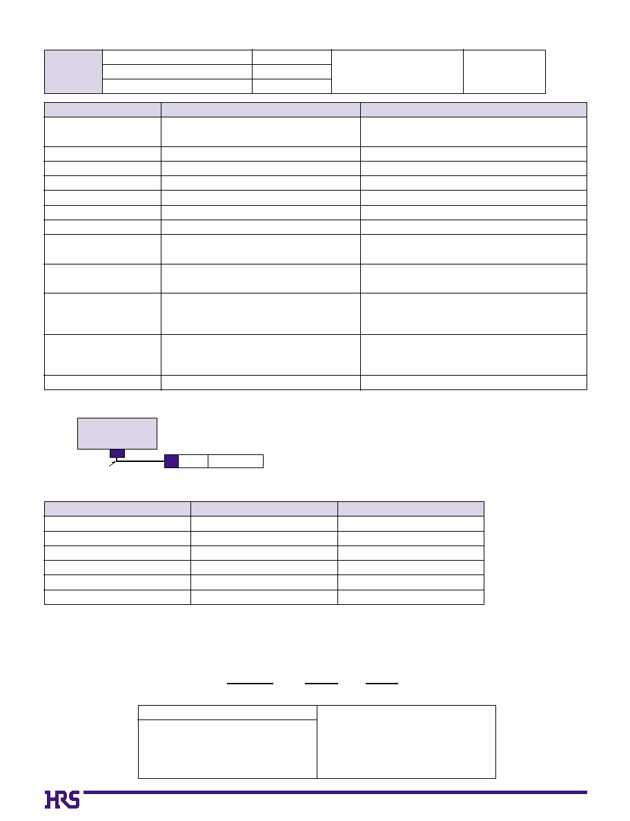
Jack Side
s
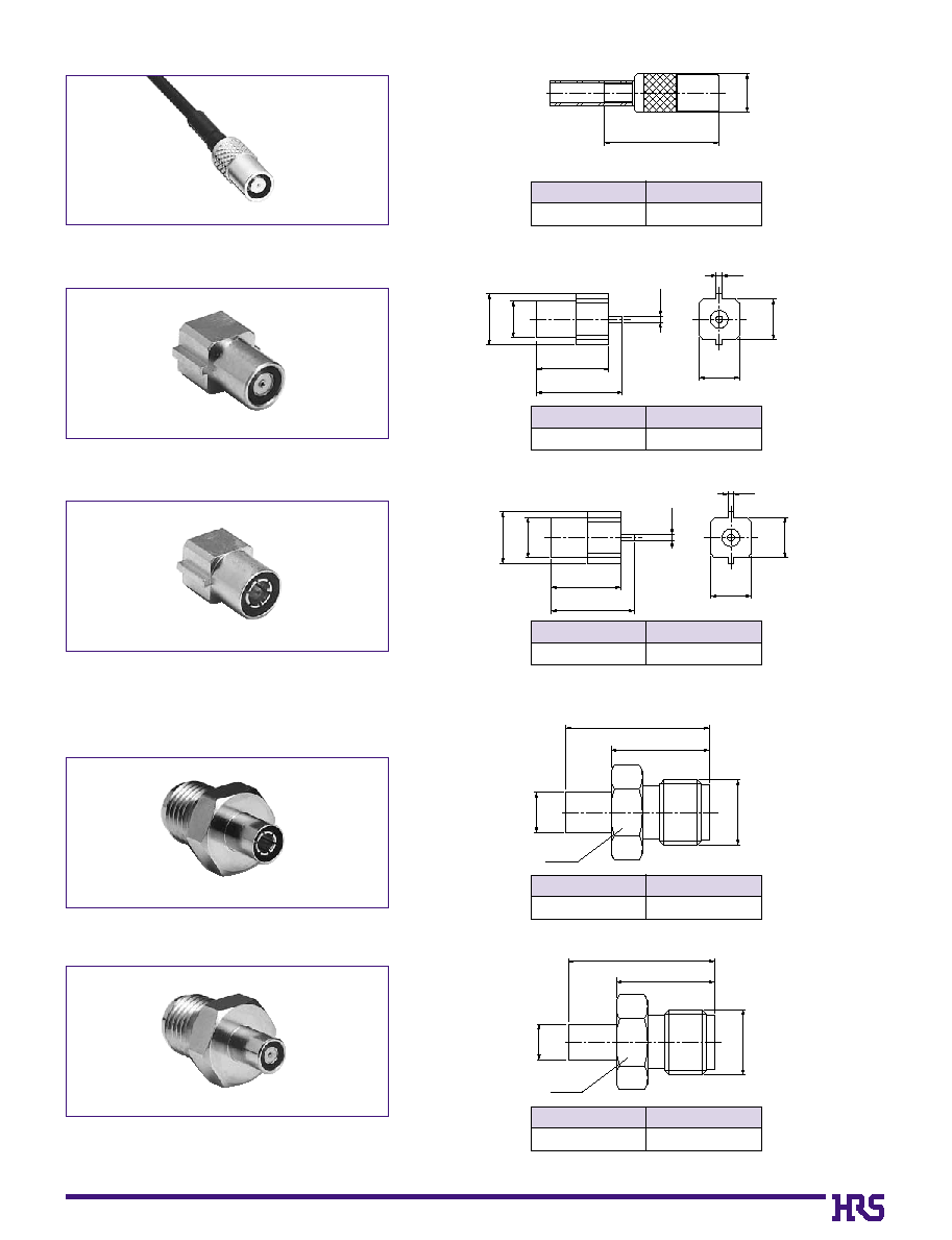
Jack
POD3-J-DFS111
s
Receptacle
POD3-R-1
s
Conversion Adapter
(Coupling portion: SMA side jack - POD3 side jack)
HRMJ-POD3J
Plug Side
s
Plug Receptacle
POD3-PR-1
s
Conversion Adapter
(Coupling portion: SMA side jack - POD3 side plug)
HRMJ-POD3P
2. Type
II
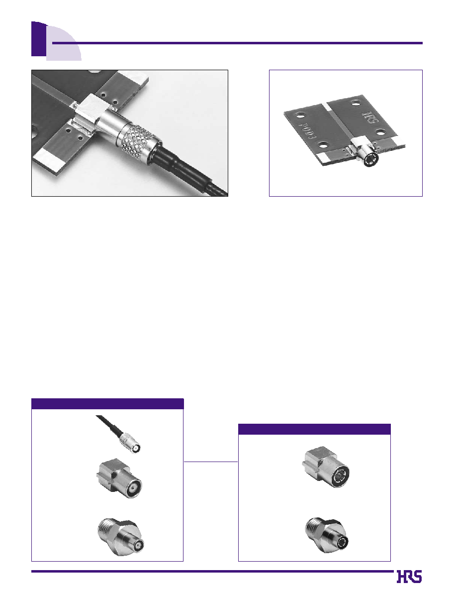
PC Card Mountable
The receptacle thickness is 3.9 mm which permits
mounting to the back side of a type II card.
(Note) that at the time of card mounting, use of 0.3mm offset of the board mounting
surface from the card center line will result in the same card center axis and
connector center axis.
3. High Degree of Matching
The top-touch system used for the coupling method
achieves high frequency performance from 0 to 3 GHz
with a V.S.W.R. of 1.3 or less.
4. Ultra-Miniature
As a complete locking type, this series achieves a size
reduction of approximately 50% in the direction of the
diameter as compared to our original POD1 Series.
5. Accommodates Ultra-Fine Cable
These connectors accommodate the use of ultra-fine
coaxial Teflon cable which permits high-density wiring
inside equipment.
ÿ
1.48 (single-layer shielded cable)
....CO-6F FH-SB manufactured by Hitachi Cable, Ltd.
....DFS111-UL1979 manufactured by Junkosha Co., Ltd.
Board Mounting Example
B24
Item
Specification
Condition
1. Contact resistance
Inner
: 10 m ohms max.
Outside : 5 m ohms max.
100 mA max.
2. Insulation resistance
500 M ohms min.
250 V DC
3. Withstanding voltage
No flashover or insulation breakdown.
300 V AC / 1 minute
4. V.S.W.R.(
*
)
1.3 max.
DC to 3 GHz
5. Female contact retention
0.2 N min.
Measured with a
ÿ
0.3 pin gauge
6. Insertion and withdrawal force (plug)
1.96 N min.
With corresponding connector
7. Durability (Insertion/withdrawal)
Contact resistance: Amount of change 10 m ohms max. 250 cycles
12. Salt spray
No marked corrosion
Exposed to density 5% salt water for 48 hours
8. Vibration
No electrical discontinuity of 1
µ
s or more
No damage, cracks, or parts looseness.
Frequency: 10 to 500 Hz, single amplitude of 0.75 mm or
acceleration of 98 m/s
2
(peak), 2 hours in each of the 3 directions.
9. Shock
No electrical discontinuity of 1
µ
s or more
No damage, cracks, or parts looseness.
Acceleration of 490 m/s
2
, 11 ms duration, sine half-wave
waveform, 10 cycles in each of the 3 axis
10. Humidity (Steady state)
Insulation resistance
100 M ohms min. (at high humidity)
500 M ohms min. (when dry)
No damage, cracks, or parts looseness.
240 hours at temperature of 25Á to 65Á and humidity of
90% to 96%
11. Temperature cycle
No damage, cracks, or parts looseness.
Temperature: -55∞C
°
5 to 35∞C
°
85∞C
°
5 to 35∞C
Time: 30
min
°
Within 5 min
°
30 min.
°
Within 5 min
Cycles: 5
s
Product Specifications
s
Ordering Information
s
Materials
part
Material
Finish
Body
Brass/Phosphor bronze
Gold and nickel plating/Gold plating
Insulator
PTFE
------------
Female inner contact
Beryllium copper
Gold plating
Male vinnerr contact
Phosphor bronze
Gold plating
Spring coil
Piano wire
Nickel plating
Heat-shrink tubing
Polyolefin
------------
POD3 ≠
[ ]
≠
[ ]
q
w
e
q
Series name: POD3
w
Connector types
J
: Jack
R
: Receptacle
PR : Plug receptacle
e
Applicable cable or suffix
DFS111: CO-6F FH-SB manufactured by
Hitachi Cable, Ltd.
DFS111-UL1979 manufactured by
Junkosha Co., Ltd.
Network Analyzer
Test Set
Test Port
Test Port Cable
D.U.T
Termination
*
Voltage standing wave ratio (V.S.W.R.) measuring system.
The above voltage standing wave ratio (V.S.W.R.) standard value is measured in the measuring system as shown below.
Note1: The cable connector is measured with double ended 10cm cable assembly.
Note2: The printed circuit board connector is mounted on the 50 ohms PCB, to
which Hirose's adaptor is connected.
Ratings
Nominal characteristic impedance
50 ohms
Voltage
100 V AC
Frequency
DC to 3 GHz
Operating temperature
-30C∞ to +85C∞
Operating humidity
95% max.