 | –≠–ª–µ–∫—Ç—Ä–æ–Ω–Ω—ã–π –∫–æ–º–ø–æ–Ω–µ–Ω—Ç: HMC256 | –°–∫–∞—á–∞—Ç—å:  PDF PDF  ZIP ZIP |
MICROWAVE CORPORATION
5 - 32
For price, delivery, and to place orders, please contact Hittite Microwave Corporation:
12 Elizabeth Drive, Chelmsford, MA 01824 Phone: 978-250-3343 Fax: 978-250-3373
Order Online at www.hittite.com
MIXERS - CHIP
5
HMC256
GaAs MMIC I/Q MIXER
5.9 - 12 GHz
v02.1103
General Description
Features
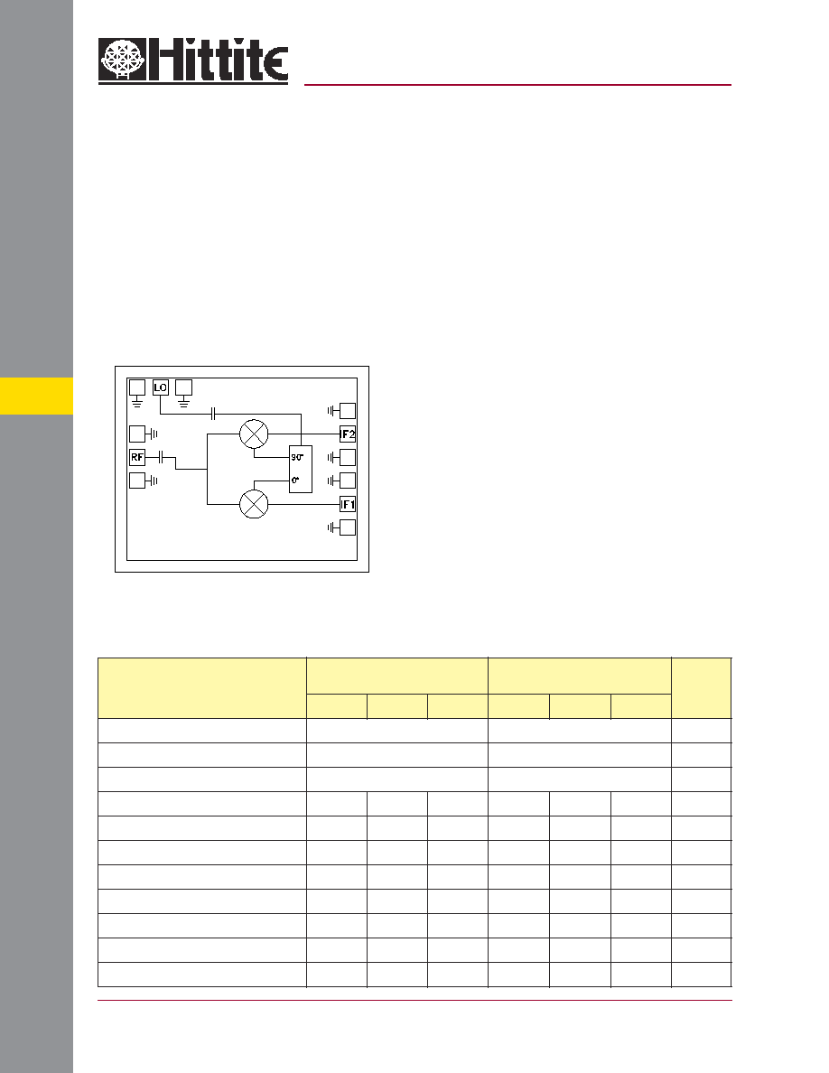
Functional Diagram
High Image Rejection: >30 dB
Input IP3: +18 dB
Wideband IF: DC to 1.5 GHz
Small Size: 1.3 mm x 1.6 mm
Electrical Specifi cations,
T
A
= +25∞ C, As an Image Reject Mixer
Typical Applications
The HMC256 is ideal for:
∑ Microwave Radio & VSAT
∑ Test Instrumentation
∑ Military Radios Radar & ECM
∑ Space
The HMC256 chip is a compact, 2.08 mm
2
, I/Q
Mixer MMIC which can be used as an Image
Reject Mixer (IRM) or SSB upconverter. The
chip utilizes two standard Hittite double-balanced
mixer cells and a Lange Coupler realized in GaAs
MESFET technology. All data is with the chip in
a 50 Ohm test fi xture connected via 0.025 mm (1
mil) diameter wire bonds of minimal length <0.51
mm (<20 mils). A low frequency quadrature hybrid
was used to interface the MMIC IF ports to a 120
MHz IF USB output. This provides an example of
the I/Q Mixer in an IRM application. The IF may
be used from DC to 1.5 GHz. This I/Q Mixer is
a more reliable, much smaller replacement to
hybrid drop-in style I/Q Mixer assemblies.
Parameter
IF = 70 - 200 MHz
LO = +18 dBm
IF = 70 - 200 MHz
LO = +15 dBm
Units
Min.
Typ.
Max.
Min.
Typ.
Max.
Frequency Range, RF
5.9 - 12
7.1 - 11.7
GHz
Frequency Range, LO
5.7 - 12
6.9 - 11.7
GHz
Frequency Range, IF
DC - 1.5
DC - 1.5
GHz
Conversion Loss
8
10.5
8
10.5
dB
Noise Figure (SSB)
8
10.5
8
10.5
dB
Image Rejection (IR)
24
32
20
30
dB
LO to RF Isolation
22
30
22
30
dB
LO to IF Isolation
27
35
27
35
dB
RF to IF Isolation
24
30
24
30
dB
IP3 (Input)
18
17
dBm
1 dB Gain Compression (Input)
5
5
dBm
MICROWAVE CORPORATION
5 - 33
For price, delivery, and to place orders, please contact Hittite Microwave Corporation:
12 Elizabeth Drive, Chelmsford, MA 01824 Phone: 978-250-3343 Fax: 978-250-3373
Order Online at www.hittite.com
MIXERS - CHIP
5
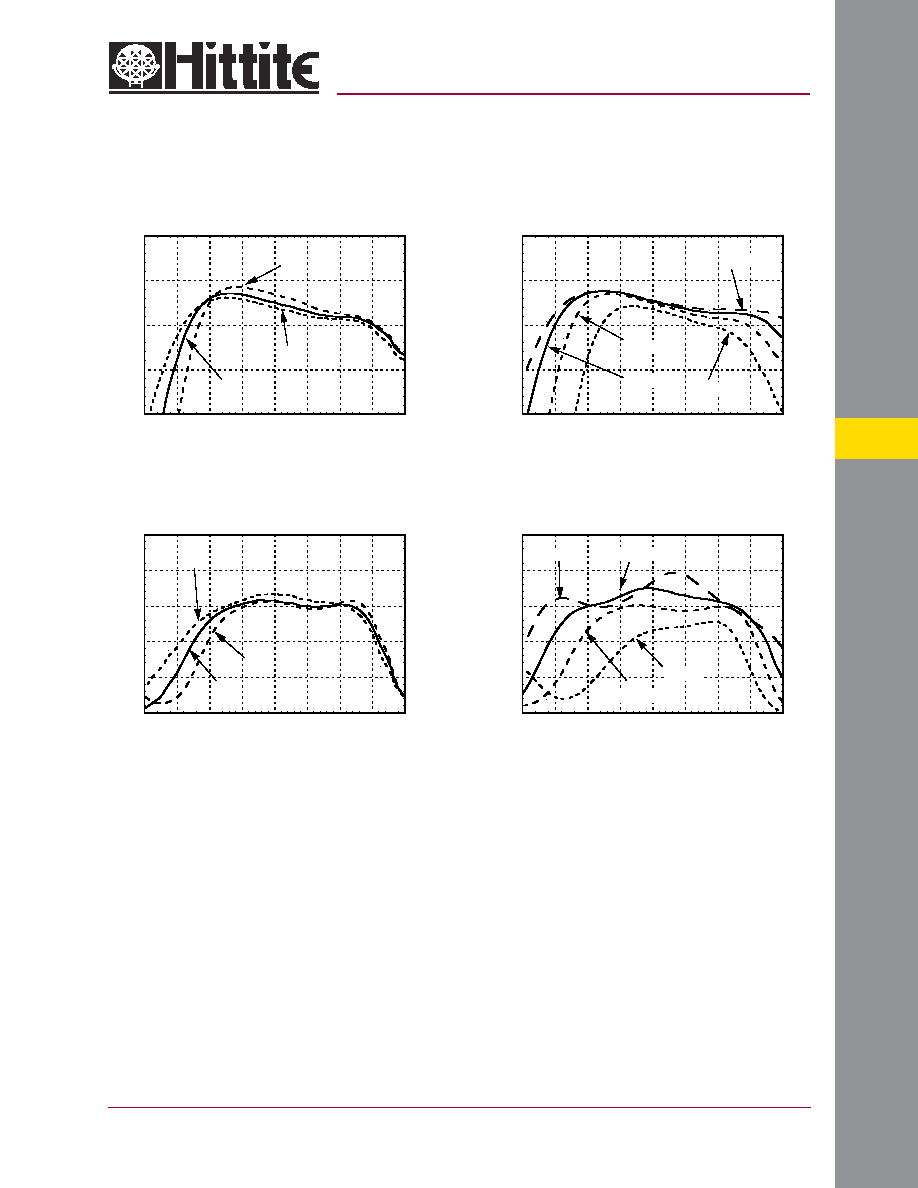
Conversion Gain to Desired Sideband
vs. Temperature @ LO = +15 dBm,
IF = 120 MHz USB
Conversion Gain to Desired Sideband
vs. LO Drive, IF = 120 MHz USB
Image Rejection vs. Temperature
LO = +15 dBm, IF = 120MHz USB
v02.1103
Image Rejection vs.
LO Drive, IF = 120 MHz USB
GaAs MMIC I/Q MIXER
5.9 - 12 GHz
HMC256
-20
-15
-10
-5
0
5
6
7
8
9
10
11
12
13
CONVERSION GAIN (dB)
FREQUENCY (GHz)
-55C
+85C
+25C
-20
-15
-10
-5
0
5
6
7
8
9
10
11
12
13
CONVERSION GAIN (dB)
RF FREQUENCY (GHz)
+14dBm
+16dBm
+12dBm
+18dBm
0
10
20
30
40
50
5
6
7
8
9
10
11
12
13
IMAGE REJECTION (dB)
RF FREQUENCY (GHz)
-55C
+25C
+85C
0
10
20
30
40
50
5
6
7
8
9
10
11
12
13
IMAGE REJECTION (dB)
RF FREQUENCY (GHz)
+12dBm
+16dBm
+14dBm
+18dBm
MICROWAVE CORPORATION
5 - 34
For price, delivery, and to place orders, please contact Hittite Microwave Corporation:
12 Elizabeth Drive, Chelmsford, MA 01824 Phone: 978-250-3343 Fax: 978-250-3373
Order Online at www.hittite.com
MIXERS - CHIP
5
v02.1103
HMC256
GaAs MMIC I/Q MIXER
5.9 - 12 GHz
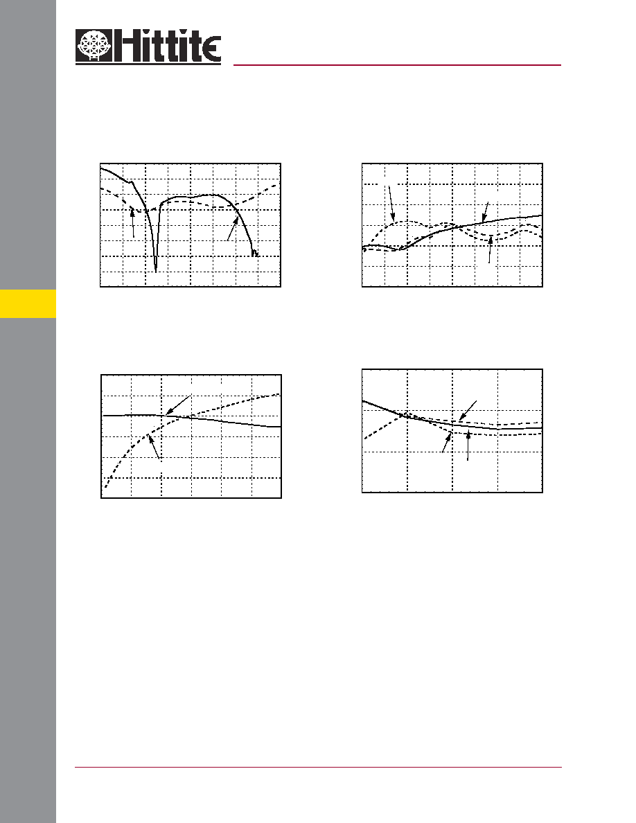
Isolations @ LO = +15 dBm
Return Loss @ LO = +15 dBm
-40
-35
-30
-25
-20
-15
-10
-5
0
5
6
7
8
9
10
11
12
13
RETURN LOSS (dB)
FREQUENCY (GHz)
RF
LO
-60
-50
-40
-30
-20
-10
0
5
6
7
8
9
10
11
12
13
ISOLATION (dB)
FREQUENCY (GHz)
LO/RF
RF/IF
LO/IF
Input IP3 vs. LO Drive, IF = 120 MHz USB
IF Bandwidth @ LO = 15 dBm
-30
-25
-20
-15
-10
-5
0
0
0.5
1
1.5
2
2.5
3
I
F
CONVERSI
ON GAI
N & RETURN LOSS (dB)
FREQUENCY (GHz)
IF Conversion Gain
Return Loss
10
15
20
25
6
6.5
7
7.5
8
THI
RD ORDER I
N
TERCEPT (dBm)
FREQUENCY (GHz)
+18dBm
+16dBm
+14dBm
MICROWAVE CORPORATION
5 - 35
For price, delivery, and to place orders, please contact Hittite Microwave Corporation:
12 Elizabeth Drive, Chelmsford, MA 01824 Phone: 978-250-3343 Fax: 978-250-3373
Order Online at www.hittite.com
MIXERS - CHIP
5
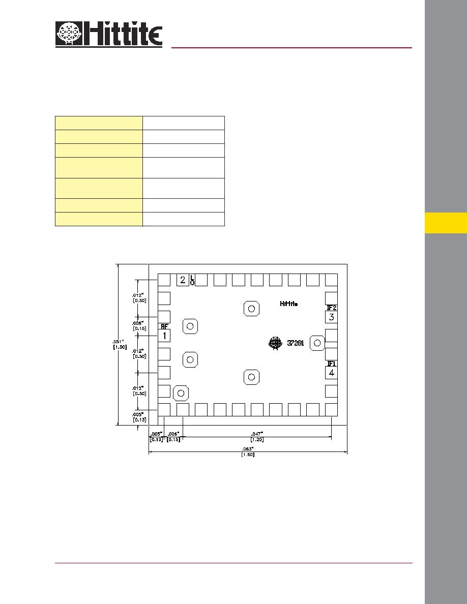
Outline Drawing
Absolute Maximum Ratings
RF / IF Input
+13 dBm
LO Drive
+27 dBm
Channel Temperature
150 ∞C
Continuous Pdiss (T = 85 ∞C)
(derate 9.36 mW/∞C above 85 ∞C)
0.61 W
Thermal Resistance (R
TH
)
(junction to die bottom)
106.8 ∞C/W
Storage Temperature
-65 to +150 ∞C
Operating Temperature
-55 to +85 ∞C
NOTES:
1. ALL DIMENSIONS ARE IN INCHES [MM].
2. BOND PADS ARE .004" SQUARE.
3. TYPICAL BOND PAD SPACING CENTER TO CENTER IS .006".
4. BACKSIDE METALLIZATION: GOLD.
5. BOND PAD METALLIZATION: GOLD.
6. BACKSIDE METAL IS GROUND.
7. CONNECTION NOT REQUIRED FOR UNLABELED BOND PADS.
v02.1103
HMC256
GaAs MMIC I/Q MIXER
5.9 - 12 GHz

MICROWAVE CORPORATION
5 - 36
For price, delivery, and to place orders, please contact Hittite Microwave Corporation:
12 Elizabeth Drive, Chelmsford, MA 01824 Phone: 978-250-3343 Fax: 978-250-3373
Order Online at www.hittite.com
MIXERS - CHIP
5
Image Reject Mixer Suggested Application Circuit
Below in Figure 1 is a photo and in Figure 2 a schematic of the HMC256 image reject mixer MMIC die connected to a quadrature
hybrid (120 MHz) manufactured by Merrimac Industries West Caldwell, NJ (P/N QHZ-2A-120).
Data presented for the HMC256 MMIC IRM was obtained using the circuit described here. Please note that the image rejection
and isolation performance is dependent on the selection of the low frequency hybrid. The performance specifi cation of the low
frequency quadrature hybrid as well as the phase balance and VSWR of the interface circuit to the HMC256 MMIC will effect the
overall IRM performance.
Figure 2:
Schematic of HMC256 IRM MMIC Connected to the Quadrature Hybrid
Figure 1:
Complete MIC IRM Assembly
v02.1103
HMC256
GaAs MMIC I/Q MIXER
5.9 - 12 GHz
Pad Number
Function
Description
Interface Schematic
1
RF
This pin is AC coupled and matched to 50 Ohm.
2
LO
This pin is AC coupled and matched to 50 Ohm.
3,4
IF1, IF2
This pin is DC coupled. For operation to DC pin must not
sink/source more than 2 mA of current or failure may result.
Backside
GND
The backside of the die must connect to RF ground.
Pad Descriptions
MICROWAVE CORPORATION
5 - 37
For price, delivery, and to place orders, please contact Hittite Microwave Corporation:
12 Elizabeth Drive, Chelmsford, MA 01824 Phone: 978-250-3343 Fax: 978-250-3373
Order Online at www.hittite.com
MIXERS - CHIP
5
v02.1103
HMC256
GaAs MMIC I/Q MIXER
5.9 - 12 GHz
Handling Precautions
Follow these precautions to avoid permanent damage.
Cleanliness: Handle the chips in a clean environment. DO NOT attempt to clean the chip using liquid cleaning systems.
Static Sensitivity: Follow ESD precautions to protect against > ± 250V ESD strikes.
Transients: Suppress instrument and bias supply transients while bias is applied. Use shielded signal and bias cables to minimize
inductive pick-up.
General Handling: Handle the chip along the edges with a vacuum collet or with a sharp pair of bent tweezers. The surface of the
chip has fragile air bridges and should not be touched with vacuum collet, tweezers, or fi ngers.
Mounting
The chip is back-metallized and can be die mounted with AuSn eutectic preforms or with electrically conductive epoxy. The mounting
surface should be clean and fl at.
Eutectic Die Attach: A 80/20 gold tin preform is recommended with a work surface temperature of 255 ∞C and a tool temperature
of 265 ∞C. When hot 90/10 nitrogen/hydrogen gas is applied, tool tip temperature should be 290 ∞C. DO NOT expose the chip
to a temperature greater than 320 ∞C for more than 20 seconds. No more than 3 seconds of scrubbing should be required for
attachment.
Epoxy Die Attach: Apply a minimum amount of epoxy to the mounting surface so that a thin epoxy fi llet is observed around the
perimeter of the chip once it is placed into position. Cure epoxy per the manufacturer's schedule.
Wire Bonding
Ball or wedge bond with 0.025 mm (1 mil) diameter pure gold wire. Thermosonic wirebonding with a nominal stage temperature of
150 ∞C and a ball bonding force of 40 to 50 grams or wedge bonding force of 18 to 22 grams is recommended. Use the minimum
level of ultrasonic energy to achieve reliable wirebonds. Wirebonds should be started on the chip and terminated on the package or
substrate. All bonds should be as short as possible <0.31 mm (12 mils).