 | ÐлекÑÑоннÑй компоненÑ: HMC-C020 | СкаÑаÑÑ:  PDF PDF  ZIP ZIP |
Äîêóìåíòàöèÿ è îïèñàíèÿ www.docs.chipfind.ru
1 - 50
For price, delivery, and to place orders, please contact Hittite Microwave Corporation:
20 Alpha Road Chelmsford, MA 01824 Phone: 978-250-3343 Fax: 978-250-3373
Order Online at www.hittite.com
A
M
P
L
IF
IE
RS
1
HMC-C020
WIDEBAND POWER AMPLIFIER
MODULE, 17 - 24 GHz
v01.0906
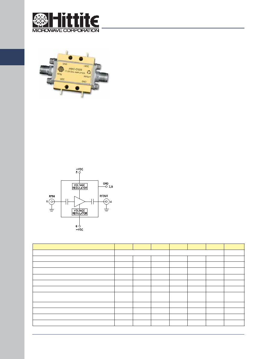
Functional Diagram
Typical Applications
General Description
Features
Electrical Specifications,
T
A
= +25° C, +VDC = +8V to +15V, -VDC = -4V to -10V*
The HMC-C020 Wideband PA is ideal for:
· Microwave Radio & VSAT
· Military & Space
· Test & Lab Instrumentation
The HMC-C020 is a GaAs MMIC PHEMT Power
Amplifi er in a miniature, hermetic module with replace-
able 2.92mm connectors which operates between 17
and 24 GHz. The amplifi er provides 22 dB of gain, 3.5
dB noise fi gure, +33 dBm output IP3 and up to +24
dBm of output power at 1 dB gain compression. The
wideband amplifi er I/Os are internally matched to 50
Ohms and are DC blocked making the HMC-C020
ideal for EW, ECM RADAR and test equipment appli-
cations. Integrated voltage regulators allow for fl ex-
ible biasing of both the negative and positive supply
pins, while internal bias sequencing circuitry assures
robust operation.
Gain: 22 dB
P1dB Output Power: +24 dBm
Noise Figure: 3.5 dB
Spurious-Free Operation
Regulated Supply and Bias Sequencing
Hermetically Sealed Module
Field Replaceable 2.92mm connectors
-55 to +85°C Operating Temperature
Parameter
Min.
Typ.
Max.
Min.
Typ.
Max.
Units
Frequency Range
17 - 20
20 - 24
GHz
Gain
19
22
24
19
22
24
dB
Gain Flatness
±1.0
±0.5
dB
Gain Variation Over Temperature
-0.03
-0.04
-0.03
-0.04
dB/ °C
Noise Figure
3.5
5.5
4.5
6.5
dB
Input Return Loss
7
7
dB
Output Return Loss
10
10
dB
Output Power for 1 dB
Compression (P1dB)
20
23
20
24
dBm
Saturated Output Power (Psat)
25
26
dBm
Output Third Order Intercept (IP3)
33
33
dBm
Positive Supply Current (+IDC)
250
250
mA
Negative Supply Current (-IDC)
5.2
5.2
mA
* Data recorded at +Vdc = +12V and - Vdc = -5V
1 - 51
For price, delivery, and to place orders, please contact Hittite Microwave Corporation:
20 Alpha Road Chelmsford, MA 01824 Phone: 978-250-3343 Fax: 978-250-3373
Order Online at www.hittite.com
A
M
P
L
IF
IE
RS
1
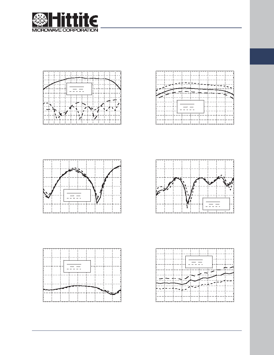
Noise Figure vs. Temperature
Gain vs. Temperature
Output Return Loss vs. Temperature
Gain & Return Loss
Reverse Isolation vs. Temperature
Input Return Loss vs. Temperature
HMC-C020
v01.0906
-30
-25
-20
-15
-10
-5
0
16
17
18
19
20
21
22
23
24
25
+25C
+85C
-55C
OUTPUT RETURN LOSS (dB)
FREQUENCY (GHz)
0
1
2
3
4
5
6
7
8
9
10
16
17
18
19
20
21
22
23
24
25
+25C
+85C
-55C
NOI
SE FI
GURE (dB)
FREQUENCY (GHz)
-60
-50
-40
-30
-20
-10
0
16
17
18
19
20
21
22
23
24
25
+25C
+85C
-55C
ISOLATION (dB)
FREQUENCY (GHz)
-30
-25
-20
-15
-10
-5
0
16
17
18
19
20
21
22
23
24
25
+25C
+85C
-55C
INPUT RETURN LOSS (dB)
FREQUENCY (GHz)
WIDEBAND POWER AMPLIFIER
MODULE, 17 - 24 GHz
6
8
10
12
14
16
18
20
22
24
26
28
30
16
17
18
19
20
21
22
23
24
25
+25C
+85C
-55C
GAIN (dB)
FREQUENCY (GHz)
-30
-25
-20
-15
-10
-5
0
5
10
15
20
25
30
13 14 15 16 17 18 19 20 21 22 23 24 25 26 27
S21
S11
S22
RESPONSE (dB)
FREQUENCY (GHz)
1 - 52
For price, delivery, and to place orders, please contact Hittite Microwave Corporation:
20 Alpha Road Chelmsford, MA 01824 Phone: 978-250-3343 Fax: 978-250-3373
Order Online at www.hittite.com
A
M
P
L
IF
IE
RS
1
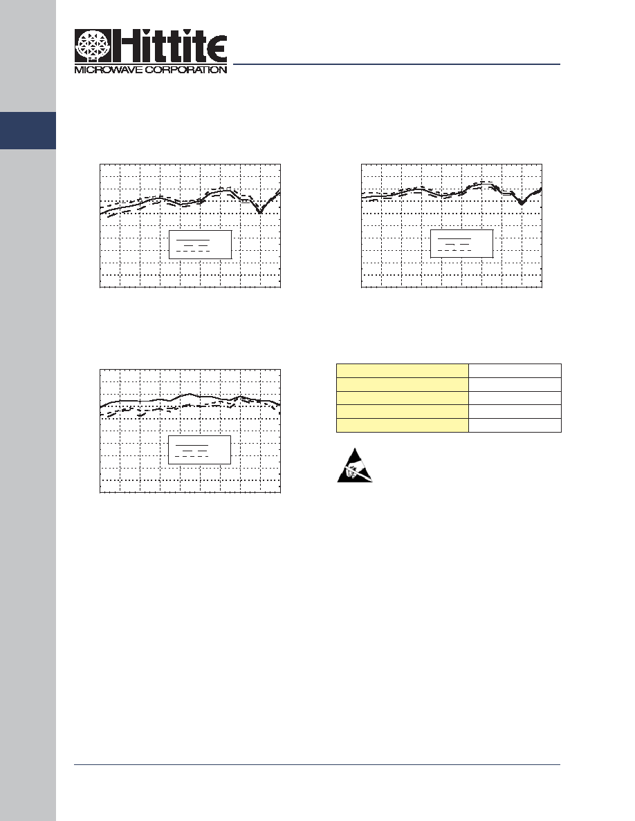
Absolute Maximum Ratings
Positive Bias Supply Voltage (+VDC)
+17V Max
Negative Bias Supply (-VDC)
-16V Min.
RF Input Power (RFin)
+20 dBm
Storage Temperature
-65 to +150 °C
Operating Temperature
-55 to +85 °C
P1dB vs. Temperature
Psat vs. Temperature
Output IP3 vs. Temperature
18
20
22
24
26
28
30
32
34
36
38
16
17
18
19
20
21
22
23
24
25
+25C
+85C
-55C
OIP3 (dBm)
FREQUENCY (GHz)
10
12
14
16
18
20
22
24
26
28
30
16
17
18
19
20
21
22
23
24
25
+25C
+85C
-55C
Psat (dBm)
FREQUENCY (GHz)
10
12
14
16
18
20
22
24
26
28
30
16
17
18
19
20
21
22
23
24
25
+25C
+85C
-55C
P1dB (dBm)
FREQUENCY (GHz)
ELECTROSTATIC SENSITIVE DEVICE
OBSERVE HANDLING PRECAUTIONS
HMC-C020
v01.0906
WIDEBAND POWER AMPLIFIER
MODULE, 17 - 24 GHz
1 - 53
For price, delivery, and to place orders, please contact Hittite Microwave Corporation:
20 Alpha Road Chelmsford, MA 01824 Phone: 978-250-3343 Fax: 978-250-3373
Order Online at www.hittite.com
A
M
P
L
IF
IE
RS
1
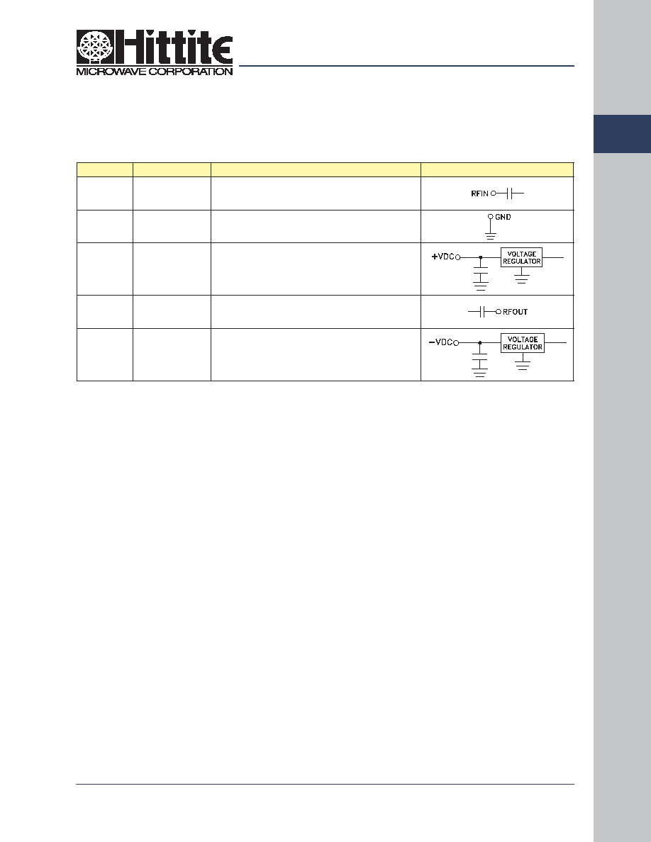
Pin Number
Function
Description
Interface Schematic
1
RFIN
RF input connector, 2.92mm female, fi eld replaceable.
This pin is AC coupled and matched to 50 Ohms
from 17 - 24 GHz.
2, 5
GND
Power supply ground.
3
+VDC
Positive power supply voltage for the amplifi er.
4
RFOUT
RF output connector, 2.92mm female. This pin is AC
coupled and matched to 50 Ohms from 17 - 24 GHz.
6
-VDC
Negative power supply voltage for the amplifi er
Pin Descriptions
HMC-C020
v01.0906
WIDEBAND POWER AMPLIFIER
MODULE, 17 - 24 GHz
1 - 54
For price, delivery, and to place orders, please contact Hittite Microwave Corporation:
20 Alpha Road Chelmsford, MA 01824 Phone: 978-250-3343 Fax: 978-250-3373
Order Online at www.hittite.com
A
M
P
L
IF
IE
RS
1
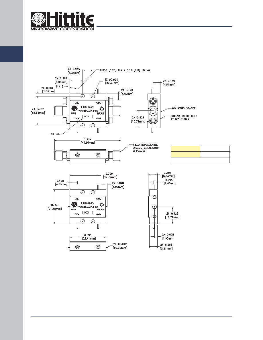
Outline Drawing
NOTES:
1. PACKAGE, LEADS, COVER MATERIAL: KOVARTM
2. PLATING: ELECTROLYTIC GOLD 50 MICROINCHES MIN., OVER
ELECTROLYTIC NICKEL 75 MICROINCHES MIN.
3. SPACER MATERIAL: NICKEL PLATED ALUMINUM
4. ALL DIMENSIONS ARE IN INCHES [MILLIMETERS].
5. TOLERANCES ±.010 [0.25] UNLESS OTHERWISE SPECIFIED.
6. FIELD REPLACEABLE 2.92MM CONNECTORS.
HMC-C020
v01.0906
WIDEBAND POWER AMPLIFIER
MODULE, 17 - 24 GHz
Typical Package Weight
Package
18.7 gms
Spacer
3.3 gms
+/- 1 gms Tolerance