 | –≠–ª–µ–∫—Ç—Ä–æ–Ω–Ω—ã–π –∫–æ–º–ø–æ–Ω–µ–Ω—Ç: HT6720 | –°–∫–∞—á–∞—Ç—å:  PDF PDF  ZIP ZIP |
Document Outline
- ˛ˇ
- ˛ˇ
- ˛ˇ
- ˛ˇ
- ˛ˇ
- ˛ˇ
- ˛ˇ
- ˛ˇ
- ˛ˇ
- ˛ˇ
- ˛ˇ
- ˛ˇ

HT6720
13.56MHz RFID Transponder
Block Diagram
Rev. 1.00
1
August 13, 2001
Features
∑
Very low operating current (4mA @ V
DD
=3V)
∑
Wide range operating voltage
∑
Batteryless RF transponder
∑
Data transmission in read-only operation
∑
Max. of 64-bits customer programmable data
∑
16-bits CRC error detection code
∑
OTP data memory
∑
13.56MHz carrier frequency
∑
Output data baud rate: 4kbps (Typ.) @ V
DD
=3V
∑
PWM/ASK modulation
∑
Built-in voltage limiter
Applications
∑
Interactive leisure products
∑
Security system
∑
Access control
∑
Anti-counterfeit devices
∑
Material management
∑
Animal management
∑
Personnel working time record
∑
Car park monitoring system
General Description
The HT6720 is an RF transponder IC with 13.56MHz RF
carrier, which provides a low cost batteryless tran-
sponder solution when combined with an external in-
ductor. The inductor and internal capacitor form an LC
tank which induce voltage from the radiated 13.56MHz
carrier signal generated from the reader antenna.
HT6720 has a built-in low power RC oscillator which is
activated if the induced carrier field strength is high
enough to supply the operating current and the re-
sponse signal (pre-programmed in the OTP memory) is
serially transmitted out. The response data is transmit-
ted using PWM/ASK modulation. Modulation of
13.56MHz is accomplished by damping the LC tank with
a fixed baud rate.
The transmission information is stored in a 96 bits one
time programmable memory OTP, with a 16-bit CRC
code (up to 64 bits reserved for customer). The effective
detection range for a small sized antenna is 2cm~10cm
which is dependent on antenna format & reader design.
The larger the antenna loop used the longer the detec-
tion range. It is advisable to use larger antenna to attain
a 15 cm detection range.
Implementing Holtek¢s advanced OTP and low power
technology, HT6720 offers a very cost effective solution
for RF contactless detection system.
A code area of 64-bits (max.) wide is provided so cus-
tomers can program the device using the specified pro-
grammer supplied by Holtek. The pre-programmed ICs
are also available upon customer¢s request.
V P A
C L K
H F 2
H F 1
V D D
V S S
P W M / A S K
M o d u l a t o r
S h i f t
R e g i s t e r
D a t a
E P R O M
S y s t e m
C l o c k
G e n e r a t o r
V C C L i m i t e r
a n d
R F L i m i t e r
D a t a
P r o c e s s i n g
P o w e r O N
R e s e t
T e s t a n d
E P R O M
P r o g r a m m i n g
C o n t r o l
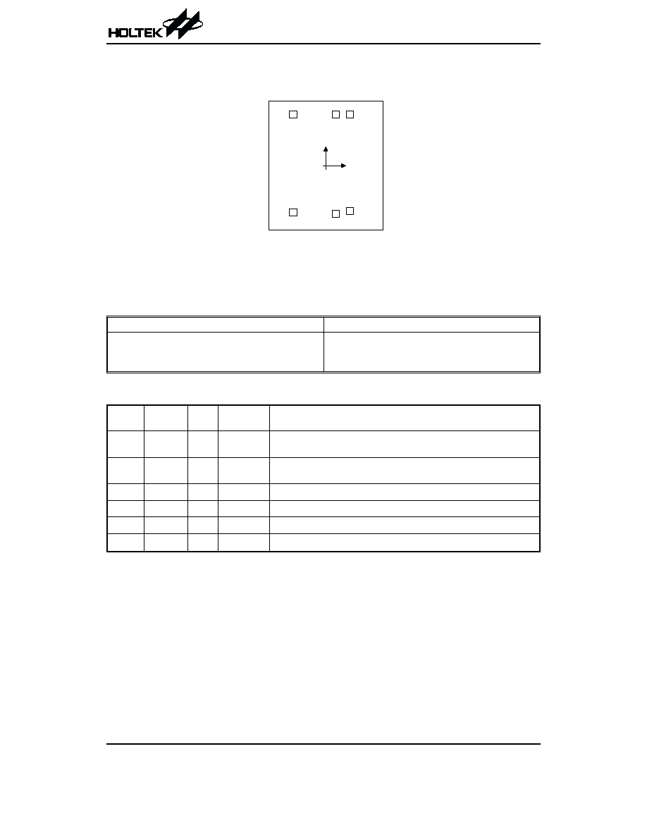
Pad Assignment
Chip size: 925¥1040 (mm)
2
* The IC substrate should be connected to VSS in the PCB layout artwork.
Pad Coordinates
Unit: mm
Pad No.
X
Y
Pad No.
X
Y
1
-256.65
357.34
4
228.70
-361.37
2
-256.65
-361.99
5
219.80
338.59
3
96.10
-378.15
6
88.89
332.15
Pad Description
Pad No. Pad Name I/O
Internal
Connection
Description
1
HF2
I/O
CMOS
Connect to an antenna coil for normal operation. Open for data program-
ming.
2
HF1
I/O
CMOS
Connect to an antenna coil for normal operation. Data I/O for program-
ming.
3
VSS
æ
æ
Negative power supply, ground
4
CLK
I
CMOS
Open for normal operation. Clock input for programming.
5
VPA
I
æ
Open for normal operation. High voltage supplies input for programming.
6
VDD
æ
æ
Open for normal operation, +5V supply input for programming.
Absolute Maximum Ratings
Supply Voltage (VDD) ...............................................6V
Storage Temperature ...........................-50∞C to 125∞C
Supply Voltage (VPA) ..........................................13.5V
Operating Temperature ..............................0∞C to 70∞C
Input Voltage .............................V
SS
-0
.
3V to V
DD
+0.3V
Note: These are stress ratings only. Stresses exceeding the range specified under ≤Absolute Maximum Ratings≤ may
cause substantial damage to the device. Functional operation of this device at other conditions beyond those
listed in the specification is not implied and prolonged exposure to extreme conditions may affect device reliabil-
ity.
HT6720
Rev. 1.00
2
August 13, 2001
( 0 , 0 )
1
2
3
4
5
6
HF
1
VS
S
CL
K
HF
2
VD
D
VP
A
Electrical Characteristics
Symbol
Parameter
Test Conditions
Min.
Typ.
Max.
Unit
V
DD
Conditions
V
DD
Operating Voltage
æ
V
DD
pad voltage
2.4
æ
5
V
I
dd
Operating Current
3V
æ
æ
4
æ
mA
5V
Voltage limiter not started
æ
10
æ
mA
R
m
Modulation Resistance
5V
æ
æ
320
æ
W
V
LCL
LC Input Limiter Voltage
æ
æ
æ
6.5
æ
V
B
R
Output Data Baud Rate
3V
V
DD
vs V
SS
æ
4
æ
Kbps
5V
V
DD
vs V
SS
æ
5.5
æ
Kbps
Timing & Code Package
HT6720
Rev. 1.00
3
August 13, 2001
Functional Description
Operation Concept
The reader transmits a 13.56MHz carrier signal from its
antenna, the LC tank on the transponder side converts
the carrier energy to voltage form and supply to the tran-
sponder chip with an internal pump circuit. If the induced
energy is high enough, the pumped voltage reaches the
break-in voltage of the internal RC-oscillator, the tran-
sponder is actuated to transmit its internal data serially
by means of damping the LC tank.
The reader receives the transponder¢s data by means of
detecting the energy variation on its own antenna, and
recognize the information with a microcontroller.
The HT6720 has a built-in internal Voltage Limiter to
prevent excess power supply and RF levels induced by
the LC tank from damaging the device or causing the
device to function abnormally.
A total of 96 bits of OTP memory space is provided, from
which 64 bits wide are customer programmable, which
can be programmed using the specified programmer
supplied by Holtek. The pre-programmed ICs are also
available upon customer¢s request.
H T 6 7 2 0
E n e r g y
D a t a
R F o s c
&
C o n t r o l l e r
T r a n s p o n d e r
R e a d e r
T r a n s p o n d e r
H T 6 7 2 0
D a t a O u t
A g e n t I D
( H o l t e k d e f i n e d )
C u s t o m e r I D
( A g e n t d e f i n e d )
( 8 b i t s )
( 8 b i t s )
( 8 b i t s )
( 5 6 b i t s )
( 1 6 b i t s )
C a t e g o r y I D
( C u s t o m e r d e f i n e d )
P r o d u c t I D
( C u s t o m e r d e f i n e d )
C R C
* C u s t o m e r P r o g r a m m a b l e
C o d e A r e a ( 6 4 b i t s M a x . )
P r o d u c t D a t a ( 6 4 b i t s )
T o t a l E P R O M s p a c e ( 9 6 b i t s )

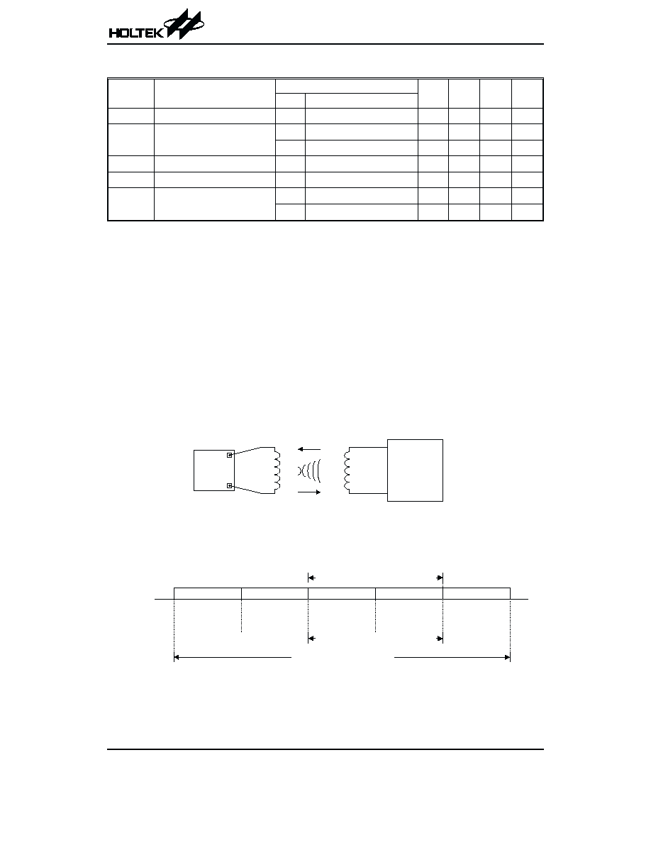
Application Circuits
Tag
A tag consists of a PCB (or Mylar film) with printed coil, HT6720 and a housing. The housing can be of various shapes.
Note: The value of the antenna inductance is 11mH, however the optimum value will be changed slightly due to the
variation of the internal resonance capacitor (10pF typically) during process.
For more application information about the reader, refer to Holtek¢s 13.56MHz RF ID reader data.
2-chip solution
HT6720
Rev. 1.00
4
August 13, 2001
Code Package
A total of 96 bits information can be stored in the
HT6720, from which 64 bits are customer programma-
ble.
Agent ID: This 8-bit wide code is not customer program-
mable and is supplied together with the data writer after
registering to Holtek. The writer generates the code au-
tomatically.
Customer ID: This area is for the Agent, for example
used to store current number of customer.
Category ID: Can be used to store the application field
information code.
Product ID: Storing the contents of the user ID number
or data.
Data CRC: A 16 bits of CRC code is generated automat-
ically by the writer.
H T 6 7 2 0
E n e r g y
D a t a
H o l t e k T r a n s p o n d e r S o l u t i o n
H o l t e k R e a d e r S o l u t i o n
O t h e r C o n t r o l l e r
R F o s c
&
R e c e i v e r
D a t a
D e c o d e
&
S y s t e m
C o n t r o l
S p e c i a l
P u r p o s e
C o n t r o l l e r
H o l t e k l o w c o s t M C U :
H T 4 8 R 0 5 A / H T 4 8 R 0 6 A
A N T
A N T
H F 2
H F 1
H T 6 7 2 0
P C B
T a g H o u s i n g

1-chip solution (I)
1-chip solution (II)
HT6720
Rev. 1.00
5
August 13, 2001
H T 6 7 2 0
E n e r g y
D a t a
H o l t e k T r a n s p o n d e r S o l u t i o n
H o l t e k R e a d e r S o l u t i o n
R F o s c
&
R e c e i v e r
D a t a
D e c o d e
&
S y s t e m
C o n t r o l
H o l t e k S t a n d a r d M C U :
H T 4 8 X X X / H T 4 9 X X X
A N T
A N T
F u n c t i o n
C o n t r o l
H T 6 7 2 0
E n e r g y
D a t a
H o l t e k T r a n s p o n d e r S o l u t i o n
H o l t e k R e a d e r S o l u t i o n
R F o s c
&
R e c e i v e r
D a t a
D e c o d e
&
S y s t e m
C o n t r o l
H o l t e k E m b e d d e d M C U :
H T 2 1 X X X / H T 8 4 X X X / H T 8 6 X X X
A N T
A N T
F u n c t i o n
C o n t r o l
D a t a , V o i c e
o r L C D
D i s p l a y
P r o c e s s i n g