 | –≠–ª–µ–∫—Ç—Ä–æ–Ω–Ω—ã–π –∫–æ–º–ø–æ–Ω–µ–Ω—Ç: HMC1021 | –°–∫–∞—á–∞—Ç—å:  PDF PDF  ZIP ZIP |

SENSOR PRODUCTS
1- and 2-Axis Magnetic
Sensors
HMC1001 / 1002
HMC1021 / 1022
Compassing
Navigation Systems
Attitude Reference
Traffic Detection
Medical Devices
Non-Contact Switch
APPLICATIONS
Wide Field Range Field range up to
±
6 gauss, (earth's field = 0.5 gauss)
Small Package
∑ Designed for 1- and 2-axis to work together to provide 3-axis (x, y, z) sensing
∑ 1-axis part in an 8-pin SIP or an 8-pin SOIC or a ceramic 8-pin DIP package
∑ 2-axis part in a 16-pin or 20-pin SOIC package
Solid State
These small devices reduce board assembly costs, improve reliability and ruggedness com-
pared to mechanical fluxgates.
On-Chip Coils
Patented on-chip set/reset straps to reduce effects of temperature drift, non-linearity errors and
loss of signal output due to the presence of high magnetic fields
Patented on-chip offset straps for elimination of the effects of hard iron distortion
Cost Effective
The sensors were specifically designed to be affordable for high volume OEM applications.
onfigured as a 4-element
wheatstone bridge, these
magnetoresistive sensors
convert magnetic fields to
a differential output volt-
age, capable of sensing
magnetic fields as low as
30
µ
gauss. These MRs
offer a small, low cost,
high sensitivity and high
reliability solution for low
field magnetic sensing.
C
FEATURES AND BENEFITS
Not actual size

LINEAR MAGNETIC FIELD SENSORS
2
HMC1001/1002 SPECIFICATIONS
Characteristics
Conditions*
Min
Typ
Max
Unit
Bridge Supply
Vbridge referenced to GND
5
12
Volts
Bridge Resistance
Bridge current = 10mA
600
850
1200
ohm
Operating Temperature (4)
-55
150
∞
C
Storage Temperature (4)
Unbiased
-55
175
∞
C
Field Range (4)
Full scale (FS), total applied field
-2
+2
gauss
Linearity Error (4)
Best fit straight line
±
1 gauss
0.1
0.5
%FS
±
2 gauss
1
2
Hysteresis Error (4)
3 sweeps across
±
2 gauss
0.05
0.10
%FS
Repeatability Error (4)
3 sweeps across
±
2 gauss
0.05
0.10
%FS
S/R Repeatability (1)
10
S/R Repeatability (2)
Output variation after alternate S/R pulses
2
100
µ
V
Bridge Offset
Offset = (OUT+) ≠ (OUT-), Field=0 gauss
-60
-15
30
mV
after Set pulse, Vbridge=8V
Sensitivity
S/R Current = 3A
2.5
3.2
4.0
mV/V/gauss
Noise Density (4)
Noise at 1 Hz, Vbridge=5V
29
nV/ Hz
Resolution (4)
Bandwidth=10Hz, Vbridge=5V
27
µ
gauss
Bandwidth (4)
Magnetic signal (lower limit = DC)
5
MHz
OFFSET Strap
Measured from OFFSET+ to OFFSET-
2.5
3.5
ohm
OFFSET Strap
Tempco (4) T
A
= -40 to 125
∞
C
0.39
%/
∞
C
OFFSET Field (4)
Field applied in sensitive direction
46
51
56
mA/gauss
Set/Reset Strap
Measured from S/R+ to S/R-
1.5
1.8
ohm
Set/Reset Current (2) (3) (4)
2
µ
s current pulse, 1% duty cycle
3.0
3.2
5
Amp
Set/Reset
Tempco (4)
T
A
= -40 to 125
∞
C
0.37
%/
∞
C
Disturbing Field (4)
Sensitivity starts to degrade.
3
gauss
Use S/R pulse to restore sensitivity.
Sensitivity Tempco (4)
T
A
= -40 to 125
∞
C Vbridge=8V
-0.32
-0.3
-0.28
%/
∞
C
Ibridge=5mA
-0.06
Bridge Offset Tempco (4)
T
A
= -40 to 125
∞
C no Set/Reset
±
0.03
%/
∞
C
Vbridge=5V with Set/Reset
±
0.001
Resistance Tempco (4)
T
A
= -40 to 125
∞
C
0.25
%/
∞
C
Cross-Axis Effect (4)
Cross field=1gauss no Set/Reset
±
3
%FS
(see AN-205) with Set/Reset
+0.5
Max. Exposed Field (4)
No perming effect on zero reading
10000
gauss
Weight
HMC1001
0.14
gram
HMC1002
0.53
(1) V
Bridge
= 4.3V, I
S/R
= 3.2A, V
OUT
= V
SET
≠ V
RESET
(2) If V
Bridge
= 8.0V, I
S/R
= 2.0A, lower S/R current leads to greater output variation.
(3) Effective current from power supply is less than 1mA.
(4) Not tested in production, guaranteed by characterization.
(*) Tested at 25
∞
C except otherwise stated.
Units: 1 gauss (g) = 1 Oersted (in air), = 79.58 A/m, 1G = 10E-4 Tesla, 1G = 10E5 gamma.

LINEAR MAGNETIC FIELD SENSORS
3
HMC1021/1022 SPECIFICATIONS
Characteristic
Conditions**
Min
Typ
Max
Unit
Bridge Supply
Vbridge referenced to GND
5
25
Volts
Bridge Resistance
Bridge current = 5mA
800
1100
1300
Operating Temperature (1)
HMC1021S, 1021Z, 1022
-55
150
∞
C
HMC1021D*
- 55
300*
Storage Temperature (1)
Unbiased
-55
175
∞
C
Field Range (1)
Full scale (FS), -- total applied field
-6
+6
gauss
Best fit straight line
±
1 gauss
0.05
Linearity Error (1)
±
3 gauss
0.4
%FS
±
6 gauss
1.6
Hysteresis Error (1)
3 sweeps across
±
3 gauss
0.08
%FS
Repeatability Error (1)
3 sweeps across
±
3 gauss
0.08
%FS
Bridge Offset
Offset = (OUT+) ≠ (OUT-), Field = 0 gauss
-10
±
2.5
11.25
mV
After Set pulse, Vbridge=5V
Sensitivity
S/R Current = 0.5A
0.8
1.0
1.25
mV/V/gauss
Noise Density (1)
Noise at 1Hz, Vbridge=5V
48
nV/
Hz
Resolution (1)
Bandwidth=10Hz, Vbridge=5V
85
µ
gauss
Bandwidth (1)
Magnetic signal (lower limit = DC)
5
MHz
OFFSET Strap
Measured from OFFSET+ to OFFSET-
38
50
60
OFFSET Strap
Tempco (1)
T
A
= -40 to 125
∞
C
0.39
%/
∞
C
OFFSET Field (1)
Field applied in sensitive direction
4.0
4.6
6.0
mA/gauss
Set/Reset Strap
Measured from S/R+ to S/R-
5.5
7.7
9
Set/Reset Current
2
µ
s current pulse, 1% duty cycle
0.5
0.5
4.0
Amp
Set/Reset
Tempco (1)
T
A
= -40 to 125
∞
C
0.37
%/
∞
C
Disturbing Field (1)
Sensitivity starts to degrade. Use S/R
20
gauss
pulse to restore sensitivity.
Sensitivity Tempco (1)
T
A
= -40 to 125
∞
C Vbridge=5V
-0.32
-0.3
-0.28
%/
∞
C
Ibridge=5mA
-0.06
Bridge Offset Tempco (1)
T
A
= -40 to 125
∞
C no Set/Reset
±
0.05
%/
∞
C
Vbridge=5V with Set/Reset
±
0.001
Resistance Tempco (1)
Vbridge=5V, T
A
= ≠40 to 125
∞
C
0.25
%/
∞
C
Cross-Axis Effect (1)
Cross field=1 gauss
(see AN-205) Happlied=
±
1 gauss
+0.3
%FS
Max. Exposed Field (1)
No perming effect on zero reading
10000
gauss
Set/Reset (1)
S/R current
0.5 Amps
30
µ
V
*Please reference data sheet, HTMC1021D for specifications.
(1) Not tested in production, guaranteed by characterization.
Units: 1 gauss (G) = 1 Oersted (in air), 1G = 79.58 A/m,
1G = 10E-4 Tesla, 1G = 10E5 gamma
**Tested at 25
∞
C except otherwise stated.

LINEAR MAGNETIC FIELD SENSORS
4
0
0.2
0.4
0.6
0.8
1
0
1
2
3
4
5
Null Voltage (mV) (Set)
Null Voltage (mV) (Reset)
Sensitivity (mV/V/Oe) (Set)
Sensitivity (mV/V/Oe) (Reset)
no set/reset in t
region
900
1000
1100
1200
1300
1400
-50
-25
0
25
50
75
100
125
1
10
100
1000
0.1
1
10
100
1000
0.6
0.7
0.8
0.9
1
1.1
1.2
1.3
-50
-25
0
25
50
75
100
125
-60
-40
-20
0
20
40
60
-20
-15
-10
-5
0
5
10
15
20
-20
-15
-10
-5
0
5
10
15
-2
-1
0
1
2
Reset
Set
KEY PERFORMANCE DATA
Sensor output vs magnetic field
after being set or reset
Vb=5V
2 sweeps
Sensor output vs magnetic field
Output is repeatable in field range
±
20 Oe
Sensitivity vs temperature
Constant voltage power supply
Vb=5V
Sensitivity (mV/V/Oe)
Sensor noise vs frequency
Vb=5V
Frequency (Hz)
Effects of set/reset pulse variation
2
µ
sec pulse duration, S/R voltage >4V is recommended
Vb=5V
Bridge resistance vs temperature
Noise Density (nV/rt Hz)
V
oltage Output (mV)
Temperature (C)
Field (Oe)
Resistance (ohm)
Nonrepeatability
Set/Reset Voltage (V)
Temperature (C)
Field (Oe)
Output V
oltage
(mV)
2 sweeps
Vb=5V
Vb=5V
1021/1022
1021/1022
1021/1022
1021/1022
All types
1021/1022
no set/reset in
this region
LINEAR MAGNETIC FIELD SENSORS
5
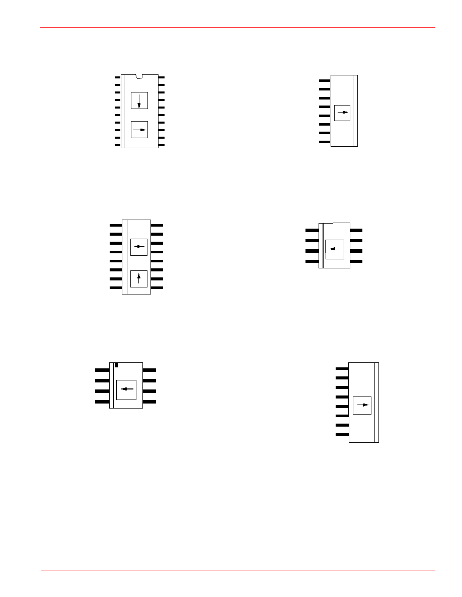
OUT+ 1
VBRIDGE 2
GND 3
OUT- 4
Die
∑
8 OFFSET-
7 OFFSET+
6 S/R-
5 S/R+
HMC1021S
OFFSET- (A) 1
OUT+ (A) 2
VBRIDGE (A) 3
OUT- (A) 4
OUT- (B) 5
VBRIDGE (B) 6
GND (A) 7
S/R+ (B) 8
Die A
∑
Die B
16 OFFSET+ (A)
15 S/R- (A)
14 S/R+ (A)
13 GND (B)
12 OUT+ (B)
11 OFFSET- (B)
10 OFFSET+ (B)
9
S/R- (B)
OUT- 1
VBRIDGE 2
S/R+ 3
GND 4
S/R- 5
OFFSET+ 6
OFFSET- 7
OUT+ 8
Die
∑
HMC1002--Two-Axis MR Microcircuit
GND1 (A) 1
OUT+ (A) 2
OFFSET- (A) 3
Vbridge (A) 4
OUT- (A) 5
GND2 (A) 6
S/R- (B) 7
GND1 (B) 8
Out+ (B) 9
OFFSET- (B) 10
20 S/R- (A)
19 NC
18 GND PLN
17 OFFSET (+A)
16 S/R+ (A)
15 OFFSET+ (B)
14 S/R+ (B)
13 GND2 (B)
12 OUT- (B)
11 Vbridge (B)
Die B
Die A
Arrow indicates direction of applied field that generates a
positive output voltage after a SET pulse.
HMC1001--One Axis MR Microcircuit
S/R+ 1
OFFSET+ 2
S/R- 3
GND 4
Out+ 5
OFFSET- 6
Vbridge 7
Out- 8
Die
∑
PACKAGE / PINOUT SPECIFICATIONS
HMC1022--Two-Axis MR Circuit
HMC1021S--One-Axis MR Circuit
HMC1021Z--One-Axis MR Circuit
HMC1021D--One-Axis MR Circuit
OUT+ 1
VBRIDGE 2
GND 3
OUT- 4
Die
8 OFFSET-
7 OFFSET+
6 S/R-
5 S/R+