 | –≠–ª–µ–∫—Ç—Ä–æ–Ω–Ω—ã–π –∫–æ–º–ø–æ–Ω–µ–Ω—Ç: BQ2057 | –°–∫–∞—á–∞—Ç—å:  PDF PDF  ZIP ZIP |

bq2057, bq2057C
bq2057W, bq2057T
SLUS025C ≠ MAY 2001 ≠ REVISED JUNE 2001
ADVANCED LINEAR CHARGE MANAGEMENT IC
FOR SINGLE- AND TWO-CELL LITHIUM-ION AND LITHIUM-POLYMER
1
www.ti.com
FEATURES
D
Ideal for Single (4.1 V or 4.2 V) and Dual-Cell
(8.2 V or 8.4 V) Li-Ion or Li-Pol Packs
D
Requires Small Number of External
Components
D
0.3 V Dropout Voltage for Minimizing Heat
Dissipation
D
Better Than
±
1% Voltage Regulation Accuracy
With Preset Voltages
D
AutoComp
t
Dynamic Compensation of
Battery Pack's Internal Impedance to Reduce
Charge Time
D
Optional Cell-Temperature Monitoring Before
and During Charge
D
Integrated Voltage and Current Regulation
With Programmable Charge-Current and High-
or Low-Side Current Sensing
D
Integrated Cell Conditioning for Reviving
Deeply Discharged Cells and Minimizing Heat
Dissipation During Initial Stage Of Charge
D
Charge Status Output for Single or Dual Led
or Host Processor Interface
D
Automatic Battery-Recharge Feature
D
Charge Termination by Minimum Current
D
Automatic Low-Power Sleep Mode When V
CC
Is Removed
D
EVMs Available for Quick Evaluation
D
Packaging: 8-Pin SOIC, 8-Pin TSSOP, 8-Pin
MSOP
DESCRIPTION
The BENCHMARQ bq2057 series advanced
Lithium-Ion (Li-Ion) and Lithium-Polymer (Li-Pol) linear
charge-management ICs are designed for cost-
sensitive and compact portable electronics. They
combine high-accuracy current and voltage regulation,
battery conditioning, temperature monitoring, charge
termination, charge-status indication, and AutoComp
charge-rate compensation in a single 8-pin IC. MSOP,
TSSOP, and SOIC package options are offered to fit a
wide range of end applications.
The bq2057 continuously measures battery
temperature using an external thermistor. For safety,
the bq2057 inhibits charge until the battery temperature
is within user-defined thresholds. The bq2057 then
charges the battery in three phases: conditioning,
constant current, and constant voltage. If the battery
voltage is below the low-voltage threshold, V
(min)
, the
bq2057 precharges using a low current to condition the
battery. The conditioning charge rate is approximately
10% of the regulation current. The conditioning current
also minimizes heat dissipation in the external pass-
element during the initial stage of the charge. After
conditioning, the bq2057 applies a constant current to
the battery. An external sense-resistor sets the current.
The sense-resistor can be on either the high or low side
of the battery without additional components. The
constant-current phase continues until the battery
reaches the charge-regulation voltage.
COMP
CC
VSS
STAT
8
7
6
5
1
2
3
4
SNS
BAT
VCC
TS
bq2057xSN or bq2057xTS
SOIC (SN) or TSSOP (TS) PACKAGE
(TOP VIEW)
BAT
SNS
COMP
CC
8
7
6
5
1
2
3
4
VCC
TS
STAT
VSS
bq2057xDGK
MSOP (DGK) PACKAGE
(TOP VIEW)
PRODUCTION DATA information is current as of publication date.
Products conform to specifications per the terms of Texas Instruments
standard warranty. Production processing does not necessarily include
testing of all parameters.
AutoComp is a trademark of Texas Instruments.
Copyright
2001, Texas Instruments Incorporated
Please be aware that an important notice concerning availability, standard warranty, and use in critical applications of
Texas Instruments semiconductor products and disclaimers thereto appears at the end of this data sheet.

bq2057, bq2057C
bq2057W, bq2057T
SLUS025C ≠ MAY 2001 ≠ REVISED JUNE 2001
2
www.ti.com
DESCRIPTION (continued)
The bq2057 then begins the constant-voltage phase. The accuracy of the voltage regulation is better than
±
1%
over the operating-temperature and supply-voltage ranges. For single and dual cells, the bq2057 is offered in
four fixed-voltage versions: 4.1 V, 4.2 V, 8.2 V, and 8.4 V. Charge stops when the current tapers to the charge
termination threshold, I
(TERM)
. The bq2057 automatically restarts the charge if the battery voltage falls below
the V
(RCH)
threshold.
The designer also may use the AutoComp feature to reduce charging time. This proprietary technique allows
safe and dynamic compensation for the internal impedance of the battery pack during charge.
AVAILABLE OPTIONS
PACKAGE
TA
CHARGE REGULATION
VOLTAGE
SOIC
(SN)
TSSOP
(TS)
MSOP
(DGK)
4.1 V
bq2057SN
bq2057TS
bq2057DGK
20
∞
C to 70
∞
C
4.2 V
bq2057CSN
bq2057CTS
bq2057CDGK
≠ 20
∞
C to 70
∞
C
8.2 V
bq2057TSN
bq2057TTS
Not available
8.4 V
bq2057WSN
bq2057WTS
Not available
Note the difference in pinout for this package.
bq2057, bq2057C
bq2057W, bq2057T
SLUS025C ≠ MAY 2001 ≠ REVISED JUNE 2001
3
www.ti.com
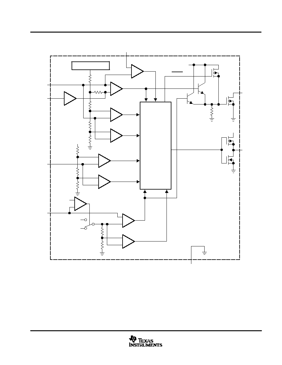
function block diagram
_
+
Sleep Mode
_
+
VCC
DONE
V-Control
I-Control
_
+
Voltage Regulation
Internal Reference
_
+
Battery
Recharge
Battery
Conditioning
_
+
_
+
VCC
TS2 Trip
TS1 Trip
_
+
_
+
Current Regulation
_
+
Charge Termination
High/Low SNS Set
VCC≠V(SNS)
VSS≠V(SNS)
VCC
0.5 VCC
I-Control
Control
Block
G(comp)
BAT
COMP
TS
SNS
CC
SAT
VSS
VCC

bq2057, bq2057C
bq2057W, bq2057T
SLUS025C ≠ MAY 2001 ≠ REVISED JUNE 2001
4
www.ti.com
Terminal Functions
TERMINAL
NO.
I/O
DESCRIPTION
NAME
SOIC (SN) and
TSSOP (TS)
MSOP
(DGK)
I/O
DESCRIPTION
BAT
2
8
I
Voltage sense input
CC
7
5
O
Charge control output
COMP
8
6
I
Charge-rate compensation input (AutoComp)
SNS
1
7
I
Current sense input
STAT
5
3
O
Charge status output
TS
4
2
I
Temperature sense input
VCC
3
1
I
Supply voltage
VSS
6
4
Ground
detailed description
current-sense input
Battery current is sensed via the voltage developed on this pin by an external sense resistor. The external
resistor can be placed on either the high or low side of the battery. (See schematics for details.)
battery-voltage input
Voltage sense-input tied directly to the positive side of the battery.
temperature sense input
Input for an external battery-temperature monitoring circuit. Connecting this input to VCC/2 disables this feature.
charge-status output
3-state indication of charge in progress, charge complete, and temperature fault or sleep mode.
charge-control output
Source-follower output that drives an external pass-transistor (PNP or P-channel MOSFET) for current and
voltage regulation.
charge-rate compensation input
Sets the charge-rate compensation level. The voltage-regulation output may be programmed to vary as a
function of the charge current delivered to the battery.
supply voltage input
Power supply input and current reference for high-side sensing configuration.

bq2057, bq2057C
bq2057W, bq2057T
SLUS025C ≠ MAY 2001 ≠ REVISED JUNE 2001
5
www.ti.com
absolute maximum ratings over operating free-air temperature (unless otherwise noted)
Supply voltage (V
CC
with respect to GND)
≠0.3 to +18 V
. . . . . . . . . . . . . . . . . . . . . . . . . . . . . . . . . . . . . . . . . . . . . . . . . .
Input voltage, SNS, BAT, TS, COMP (all with respect to GND)
≠0.3 V to V
CC
+0.3 V
. . . . . . . . . . . . . . . . . . . . . . . . . .
Sink current (STAT pin) not to exceed P
D
20 mA
. . . . . . . . . . . . . . . . . . . . . . . . . . . . . . . . . . . . . . . . . . . . . . . . . . . . . . . . .
Source current (STAT pin) not to exceed P
D
10 mA
. . . . . . . . . . . . . . . . . . . . . . . . . . . . . . . . . . . . . . . . . . . . . . . . . . . . . .
Output current (CC pin) not to exceed P
D
40 mA
. . . . . . . . . . . . . . . . . . . . . . . . . . . . . . . . . . . . . . . . . . . . . . . . . . . . . . . .
Total power dissipation, P
D
(at 25
∞
C)
300mW
. . . . . . . . . . . . . . . . . . . . . . . . . . . . . . . . . . . . . . . . . . . . . . . . . . . . . . . . . . .
Operating free-air temperature range, T
A
≠20
∞
C to 70
∞
C
. . . . . . . . . . . . . . . . . . . . . . . . . . . . . . . . . . . . . . . . . . . . . . . . . .
Storage temperature range, T
stg
≠40
∞
C to 125
∞
C
. . . . . . . . . . . . . . . . . . . . . . . . . . . . . . . . . . . . . . . . . . . . . . . . . . . . . . . .
Lead temperature (soldering, 10 s)
300
∞
C
. . . . . . . . . . . . . . . . . . . . . . . . . . . . . . . . . . . . . . . . . . . . . . . . . . . . . . . . . . . . . .
Stresses beyond those listed under "absolute maximum ratings" may cause permanent damage to the device. These are stress ratings only, and
functional operation of the device at these or any other conditions beyond those indicated under "recommended operating conditions" is not
implied. Exposure to absolute-maximum-rated conditions for extended periods may affect device reliability.
DISSIPATION RATING TABLE
PACKAGE
DERATING FACTOR
ABOVE TA
25
∞
C
TA
25
∞
C
POWER RATING
TA = 70
∞
C
POWER RATING
DGK
3.4 mW/
∞
C
424 mW
271 mW
recommended operating conditions
MIN
MAX
UNIT
Supply voltage, VCC
4.5
15
V
Operating free-air temperature range, TA
≠20
70
∞
C
electrical characteristics over recommended operating free-air temperature range (unless
otherwise noted)
PARAMETER
TEST CONDITIONS
MIN
TYP
MAX
UNIT
I(VCC)
VCC Current
VCC > VCC(min), Excluding external loads
2
4
mA
I
V
Sleep current
For bq2057 and bq2957C,
V(BAT)
V(min), V(BAT) ≠ VCC
0.8 V
3
6
A
I(VCCS)
VCC Sleep current
For bq2057T and bq2957W,
V(BAT)
V(min), V(BAT) ≠ VCC
0.8 V
10
µ
A
IIB(BAT)
Input bias current on BAT pin
V(BAT) = V(REG)
1
µ
A
IIB(SNS)
Input bias current on SNS pin
V(SNS)= 5 V
5
µ
A
IIB(TS)
Input bias current on TS pin
V(TS) = 5 V
5
µ
A
IIB(COMP) Input bias current on COMP pin
V(COMP) = 5 V
5
µ
A
BATTERY VOLTAGE REGULATION
4.059
4.10
4.141
V
Output voltage
V
+0 3 V
V
V
See Notes 1 and 2
4.158
4.20
4.242
V
VO(REG)
Output voltage
V(BAT)+0.3 V
VCC
VCC(max), See Notes 1 and 2
8.119
8.20
8.282
V
8.317
8.40
8.484
NOTES:
1. For high-side current sensing configuration
2. For low-side current sensing configuration, the tolerance is
±
1% for TA = 25
∞
C and
±
1.2% for ≠20
∞
C
TA
70
∞
C