 | –≠–ª–µ–∫—Ç—Ä–æ–Ω–Ω—ã–π –∫–æ–º–ø–æ–Ω–µ–Ω—Ç: UCC3956 | –°–∫–∞—á–∞—Ç—å:  PDF PDF  ZIP ZIP |

UCC2956, UCC3956
SWITCH MODE LITHIUM ION
BATTERY CHARGE CONTROLLER
SLUS249A ≠ FEBRUARY 1997 ≠ REVISED SEPTEMBER 2000
1
POST OFFICE BOX 655303
∑
DALLAS, TEXAS 75265
D
Precision 4.1 V Reference (1%)
D
High-Efficiency Battery Charger Solution
D
High-Side or Low-Side Switch-Mode
Current-Sensing
D
Average-Current-Mode Control from Trickle
to Overcharge
D
Resistor-Programmable Charge Currents
D
Internal State Logic Provides Four Charge
States
D
Programmable Overcharge Time
D
CHG Pin Initiates Charging
D
Output-Status Bits Report Charge State
description
The UCC3956 family of switch-mode lithium-ion battery-charger controllers accurately control lithium-ion
battery charging with a highly-efficient average-current-control loop. This chip is designed to work as a
stand-alone charger controller for a single-cell or multiple-cell battery pack. This chip combines charge-state
logic and average-current PWM control circuitry with a 14-bit counter to program the overcharge time. The
charge-state logic indicates current- or voltage-control depending on the charge state. The chip includes
undervoltage lockout (UVLO) circuitry to ensure sufficient supply voltage is present before output switching
starts. Additional circuit blocks include a differential-current-sense amplifier, a 1% voltage reference, voltage-
and current-error amplifiers, PWM latch, charge-state decode bits, and a 500-mA output driver.
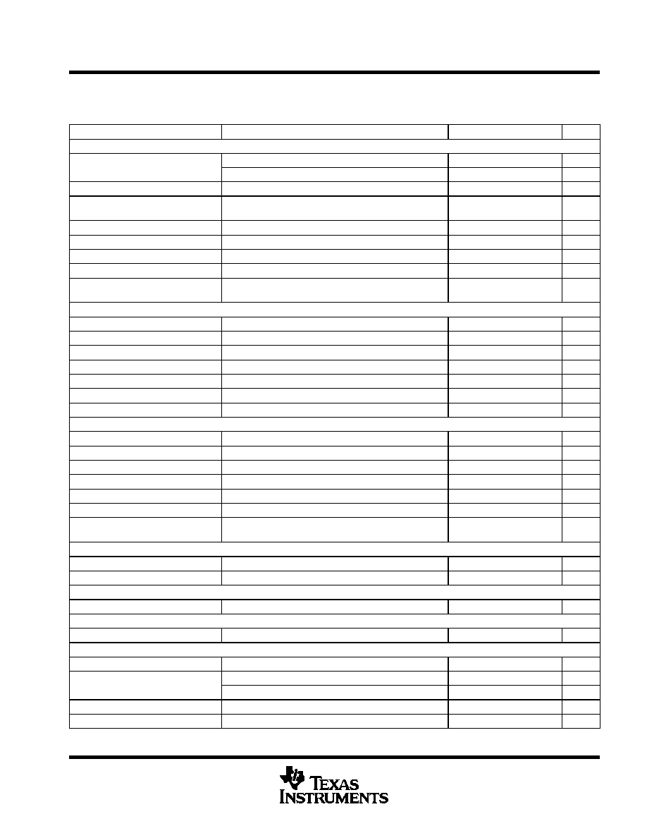
absolute maximum ratings over operating free-air temperature range (unless otherwise noted)
Input voltage (VDD, OUT)
20 V
. . . . . . . . . . . . . . . . . . . . . . . . . . . . . . . . . . . . . . . . . . . . . . . . . . . . . . . . . . . . . . . . . .
Output current sink
Continuous
120 mA
. . . . . . . . . . . . . . . . . . . . . . . . . . . . . . . . . . . . . . . . . . . . . . . . . . . . . . . . . . . . . . . . . . . . . . .
Peak
600 mA
. . . . . . . . . . . . . . . . . . . . . . . . . . . . . . . . . . . . . . . . . . . . . . . . . . . . . . . . . . . . . . . . . . . . . . . . . . . .
Output current source
Continuous
120 mA
. . . . . . . . . . . . . . . . . . . . . . . . . . . . . . . . . . . . . . . . . . . . . . . . . . . . . . . . . . . . . . . . . . . . . . .
Peak
600 mA
. . . . . . . . . . . . . . . . . . . . . . . . . . . . . . . . . . . . . . . . . . . . . . . . . . . . . . . . . . . . . . . . . . . . . . . . . . . .
CS+, CS≠
Voltage
0.5 to VDD
. . . . . . . . . . . . . . . . . . . . . . . . . . . . . . . . . . . . . . . . . . . . . . . . . . . . . . . . . . . . . . . . . . . . . . .
Current with CS+, CS≠ less than ≠0.5
50 mA
. . . . . . . . . . . . . . . . . . . . . . . . . . . . . . . . . . . . . . . . . . . . . . . . .
Remaining pin voltages
≠0.3 V to 6 V
. . . . . . . . . . . . . . . . . . . . . . . . . . . . . . . . . . . . . . . . . . . . . . . . . . . . . . . . . . . .
Storage temperature range, T
stg
≠65
∞
C to 150
∞
C
. . . . . . . . . . . . . . . . . . . . . . . . . . . . . . . . . . . . . . . . . . . . . . . . . . .
Operating virtual junction temperature range, T
J
≠55
∞
C to 150
∞
C
. . . . . . . . . . . . . . . . . . . . . . . . . . . . . . . . . . . . .
Lead temperature (soldering, 10 seconds)
300
∞
C
. . . . . . . . . . . . . . . . . . . . . . . . . . . . . . . . . . . . . . . . . . . . . . . . . .
Stresses beyond those listed under "absolute maximum ratings" may cause permanent damage to the device. These are stress ratings only, and
functional operation of the device at these or any other conditions beyond those indicated under "recommended operating conditions" is not
implied. Exposure to absolute-maximum-rated conditions for extended periods may affect device reliability.
Unless otherwise indicated, voltages are reference to ground and currents are positive into and negative out of the specified terminals. Consult
Packaging Information section of the Portable Products Databook (TI Literature No. SLUD001) for thermal limitations and considerations of
packages. All voltages are referenced to GND.
Copyright
©
2000, Texas Instruments Incorporated
PRODUCTION DATA information is current as of publication date.
Products conform to specifications per the terms of Texas Instruments
standard warranty. Production processing does not necessarily include
testing of all parameters.
Please be aware that an important notice concerning availability, standard warranty, and use in critical applications of
Texas Instruments semiconductor products and disclaimers thereto appears at the end of this data sheet.
1
2
3
4
5
6
7
8
9
10
20
19
18
17
16
15
14
13
12
11
CHGENB
IMIN
CS≠
CS+
CHG
STAT1
STAT0
REF
VDD
OUT
VA+
VA≠
VAO
IBAT
CA≠
CAO
CTO
RSET
COSC
GND
J, N, DW PACKAGES
(TOP VIEW)

UCC2956, UCC3956
SWITCH MODE LITHIUM ION
BATTERY CHARGE CONTROLLER
SLUS249A ≠ FEBRUARY 1997 ≠ REVISED SEPTEMBER 2000
2
POST OFFICE BOX 655303
∑
DALLAS, TEXAS 75265
block diagram
UDG≠96197≠1
AVAILABLE OPTIONS
TA
PACKAGED DEVICES
TA
(N)
(J)
(DW)
≠40
∞
C to 85
∞
C
UCC2956N
UCC2956J
UCC2956DW
0
∞
C to 70
∞
C
UCC3956N
UCC3956J
UCC3956DW
The DW package is available taped and reeled. Add TR suffix to device type (e.g.
UCC2956DWTR) to order quantities of 3000 devices per reel.
UCC2956, UCC3956
SWITCH MODE LITHIUM ION
BATTERY CHARGE CONTROLLER
SLUS249A ≠ FEBRUARY 1997 ≠ REVISED SEPTEMBER 2000
3
POST OFFICE BOX 655303
∑
DALLAS, TEXAS 75265
electrical characteristics over recommended operating free-air temperature range,
T
A
= ≠40
_
C to 85
_
C for UCC2956 and T
A
= 0
_
C to 70
_
C for UCC3956, COSC = 500 pF, RSET = 70 k
,
CTO = 169 nF, VDD = 12 V, T
A
= T
J
. (unless otherwise noted)
PARAMETER
TEST CONDITIONS
MIN
TYP
MAX
UNIT
Current Sense Amplifier (CSA) Section
DC gain
CS≠ = 0,
CS+ = ≠50 mV, CS+ = ≠250 mV
4.9
5.0
5.1
V/V
DC gain
CS+ = 0,
CS≠ = 50 mV, CS≠ = 250 mV
4.9
5.0
5.1
V/V
Current sense amplifier output (CAO)
CS+ = CS≠ = 0 V
1.99
2.05
2.11
V
Common mode rejection ratio
(CMRR)
VCM = 1.1 V to 18 V,
VDD = 18 V
50
65
dB
Low-level output voltage (VOL)
CS+ = ≠0.2 V,
CS≠ = 0.5 V,
IO = 1 mA
0.2
1
V
High-level output voltage (VOH)
CS+ = 0.5 V,
CS≠ = ≠0.2 V,
IO = ≠500 mA
3.7
4.1
4.4
V
Output source current
IBAT = 3 V,
VID = 700 mV
≠500
µ
A
Output sink current
IBAT = 1 V,
VID = ≠700 mV
500
µ
A
3dB bandwidth
VCM = 0 V,
CS+ ≠ CS≠ = 100 mV,
See Note 2
0.1
3.0
MHz
Current Error Amplifier (CEA) Section
Bias current
8 V < VDD < 18 V,
CHGENB = REF
0.1
0.5
µ
A
Current error amplifier voltage
8 V < VDD < 18 V,
CAO = CA≠
1.99
2.05
2.11
V
Open-loop voltage gain (AVOL)
60
90
dB
Gain bandwidth
TJ = 25
∞
C,
F = 100 kHz
1
3
MHz
Low-level output voltage (VOL)
IO = 250
µ
A,
CA≠ = 3 V
0.2
1.0
V
High-level output voltage (VOH)
IO = ≠1 mA,
CA≠ = 2 V
3.7
4.1
4.4
V
ICA≠, ITRCK_CONTROL
VCHGENB = GND
8
10
12
µ
A
Voltage Error Amplifier (VEA)
Bias current
Total bias current;
Regulating level
0.5
3.0
µ
A
Input offset voltage
8 V < VDD < 18 V,
VCM = 4.1 V
10
mV
Open-loop voltage gain (AVOL)
60
90
dB
Gain bandwidth
TJ = 25
∞
C,
F = 100 kHz
0.75
3.00
MHz
Low-level output voltage (VOL)
IO = 500
µ
A,
VA≠ = 3.8 V
0.2
1.0
V
High-level output voltage (VOH)
IO = ≠500
µ
A,
VA≠ = 4.4 V
3.8
4.1
4.3
V
Voltage amplifier output leakage
VCHGENB = GND,
STAT0 = 0,
STAT1 = 0,
VAO = 2.05 V
≠1
1
µ
A
Pulse Width Modulator Section
Maximum duty cycle
CAO = 0.5 V
92
96
100
%
Modulator gain
CAO = 1.7 V to 2.1 V
57
64
71
%/V
PWM Oscillator (OSC) Section
Frequency
7 V < VDD < 18 V
90
100
110
kHz
Overcharge Timer (OCT) Section
Frequency
7 V < VDD < 18 V
See Note 1
4.65
5.00
5.35
Hz
Reference Section
Initial accuracy
TJ = 25
∞
C
4.06
4.10
4.14
V
Accuracy
0 < TJ < 70
∞
C, VDD = 8 V to 18 V
4.05
4.10
4.15
V
Accuracy
≠40
∞
C < TJ < 85
∞
C, VDD = 8 V to 18 V
4.03
4.10
4.17
V
Load regulation
0 < IO < 2 mA
3
15
mV
Short circuit I
REF = 0 V
8
20
30
mA
UCC2956, UCC3956
SWITCH MODE LITHIUM ION
BATTERY CHARGE CONTROLLER
SLUS249A ≠ FEBRUARY 1997 ≠ REVISED SEPTEMBER 2000
4
POST OFFICE BOX 655303
∑
DALLAS, TEXAS 75265
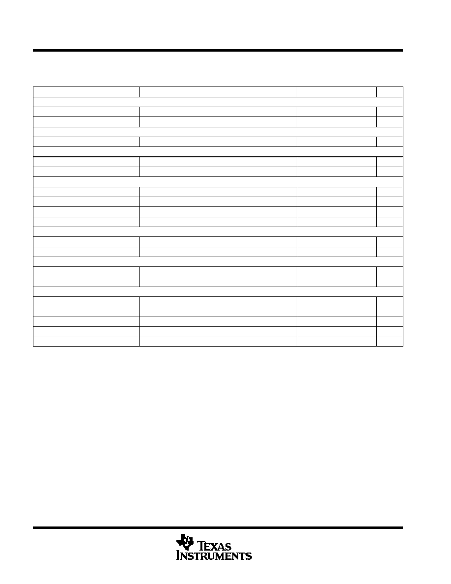
electrical characteristics over recommended operating free-air temperature range,
T
A
= ≠40
_
C to 85
_
C for UCC2956 and T
A
= 0
_
C to 70
_
C for UCC3956, COSC = 500 pF, RSET = 70 k,
CTO = 169 nF, VDD = 12 V, T
A
= T
J
. (unless otherwise noted)
PARAMETER
TEST CONDITIONS
MIN
TYP
MAX
UNIT
Charge Enable Comparator (CEC) Section
Threshold voltage
1.90
2.05
2.15
V
Input bias current
≠0.5
≠0.2
µ
A
Voltage Sense Comparator (VSC) Section
Threshold voltage
Volts below VA+
50
125
200
mV
Charge current comparator (CIC) Section
Threshold voltage
CS+ = CS≠ = 0, function of IBAT = 2.05 V
2.00
2.05
2.10
V/V
Input bias current
Total bias current; regulating level
≠0.5
≠0.2
µ
A
Output Stage Section
VOL
IOUT = 10 mA
0.1
0.3
V
VOH, volts below VDD
IOUT = ≠10 mA
0.1
0.5
V
Rise time
COUT = 1 nF
30
70
ns
Fall time
COUT = 1 nF
30
70
ns
STAT0 and STAT1 Open Drain Outputs Section
Maximum sink current
VOUT = 12 V
15
30
mA
VOL
IOUT = 1 mA
0.1
0.2
V
Charge control (CHG) Section
Threshold voltage
1.5
1.8
2.1
V
Charge-pin pull-down current
VCHG = 1 V
8
23
40
µ
A
Undervoltage Lockout Current Section
Turn≠on threshold
6.00
6.50
7.0
V
Hysteresis
75
150
400
mV
Input current
Quiescent current
5
8
mA
Undervoltage lockout current
VDD = 5 V
0.25
0.75
mA
NOTE 1: 14-bit tuner functionally tested at 500 kHz.
NOTE 2: Ensured by design, not production tested.

UCC2956, UCC3956
SWITCH MODE LITHIUM ION
BATTERY CHARGE CONTROLLER
SLUS249A ≠ FEBRUARY 1997 ≠ REVISED SEPTEMBER 2000
5
POST OFFICE BOX 655303
∑
DALLAS, TEXAS 75265
pin descriptions
CA≠: The inverting input to the current-error amplifier.
CAO: The output of the current-error amplifier and inverting input of the PWM comparator. This pin is driven
high during shutdown.
CS≠, CS+: The inverting and non-inverting inputs to the current-sense amplifier. This amplifier has a fixed-gain
of 5.
CHG: A rising-edge triggered-input pin that indicates charging. Once the internal 14-bit timer has timed out, the
chip enters its shutdown charge state. At this point, CHG is pulled low by an internal buffer. Another low-to-high
transition is required to reset the timer and restart charging.
CHGENB: The input to a comparator that detects when the battery voltage is low and places the charger in
trickle charge. The charge-enable comparator forces the output of the voltage-error amplifier to a
high-impedance state while forcing a fixed 10-
µ
A current into the CA≠ to set the trickle charge.
COSC: The oscillator ramp pin which has a capacitor (COSC) to ground. The ramp oscillates between 0.8 V
to 3.2 V and the frequency is determined by:
Frequency
+
3.475
(COSC
)
20 pF)
RSET
A rising edge on CHG initiates the oscillator.
CTO: The slow oscillator ramp pin, which is used to generate a clock signal for the 14-bit timer to program the
overcharge time. A capacitor (tied to ground) is charged and discharged with equal currents at a frequency
programmed between 0.75 Hz and 5 Hz. The ramp oscillates between 0.1 V and 3.0 V and the frequency is
determined by:
Frequency
+
0.06
(CTO
RSET)
The oscillator operates only while in overcharge.
GND: The reference point for the internal reference, all thresholds, and the return for the remainder of the
device.
IBAT: The output of the current-sense amplifier.
IMIN: The minimum-charge-current programming pin is provided to program an optional-charge termination in
addition to the programmable timer.
OUT: The output of the PWM driver.
REF: The 4.1-V precision reference, which should be bypassed with a 0.1-
µ
F capacitor.
RSET: This pin programs the charge current for the oscillator ramp. The oscillator-charge current is determined
by:
I
COSC
+
1.37 V
RSET
The trickle-control current (I
TRCK_CONTROL
) is determined by:
I
TCK_CONTROL
+
0.68 V
RSET
(1)
(2)
(3)
(4)