Integrated
Circuit
Systems, Inc.
General Description
Pentium is a trademark of Intel Corporation
Low-Cost 16-Pin Frequency Generator
AV9154A
.
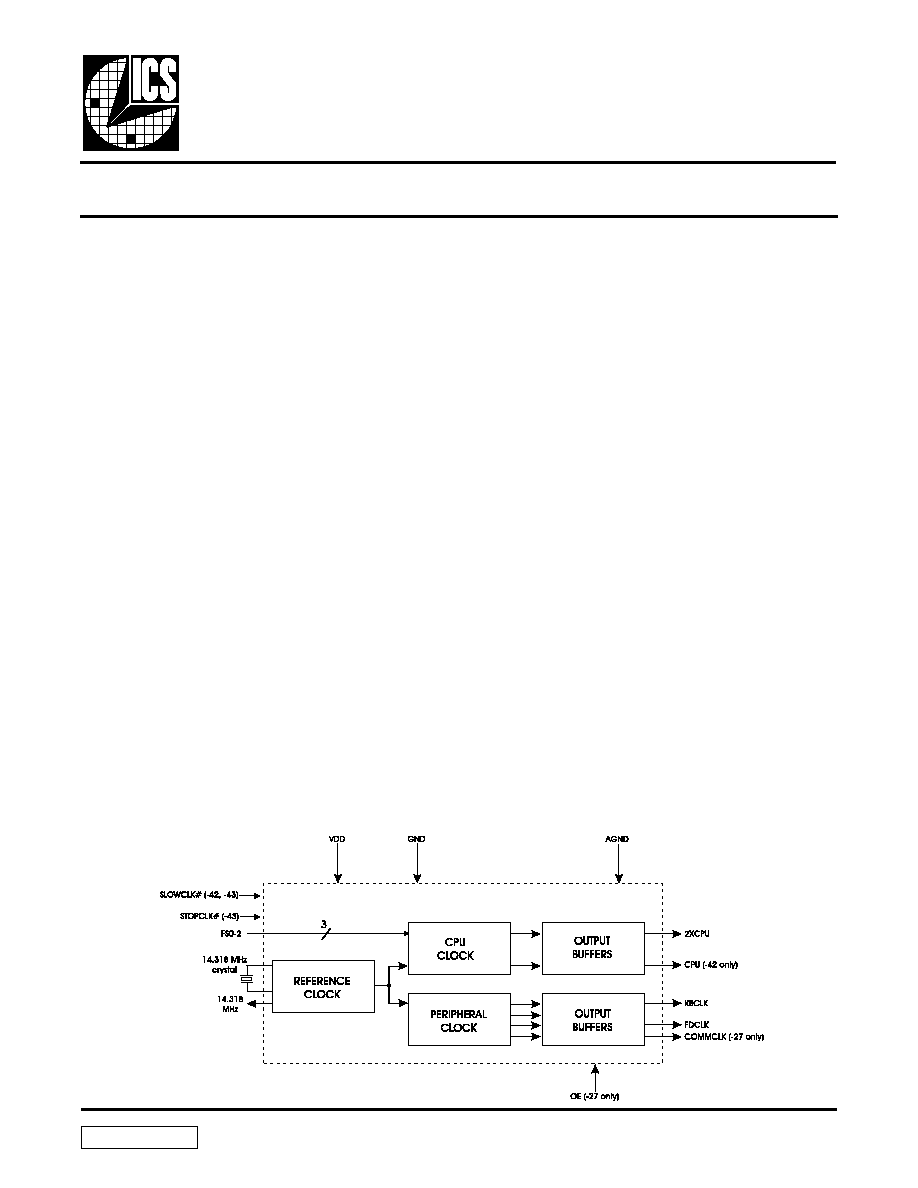
The AV9154A is a 0.8mm version of the industry leading AV9154.
Like the AV9154, the AV9154A is a low-cost frequency generator
designed for general purpose PC and disk drive applications. However,
because the AV9154A uses 0.8mm technology and the latest phase-
locked loop architecture, it offers performance advantages that
enable the device to be sold into PentiumTM systems.
The AV9154A guarantees a 45/55 duty cycle over all frequencies. In
addition, a worst case jitter of ±250ps is specified at Pentium
frequencies.
The CPU clock offers the unique feature of smooth, glitch-free
transitions from one frequency to the next, making this the ideal
device to use when slowing the CPU speed. The AV9154A makes a
gradual transition between frequencies so that it obeys the Intel
cycle-to-cycle timing specifications for 486 and Pentium systems.
The AV9154A-42 and AV9154A-43 devices offer features specifically
for green PCs. The AV9154A-42 and -43 have a single pin that,
when pulled low, will smoothly slow the 2XCPU clock to 8 MHz.
This is ideal for dynamic DX microprocessors. The AV9154A-43
not only has the slow clock feature, but also offers a glitch-free stop
clock for static SX microprocessors. The STOPCLK# pin, when
pulled low, enables the 2XCPU clock to go low only after completing
its last full cycle. The clock continues to run internally, and will be
output again on the first full cycle immediately following stop clock
disable.
The simultaneous 2X and 1X CPU clocks offer controlled skew to
within 500ps of each other (-42 only).
ICS has been shipping motherboard frequency generators since
April 1990, and is the leader in the area of multiple output clocks on
a single chip. Consult ICS for all your clock generation needs.
∑
Compatible with 386, 486 and Pentium CPUs
∑
45/55 Duty cycle
∑
Runs up to 66 MHz at 3.3V
∑
Single pin can slow clock to 8 MHz (on -42 and -43)
∑
Single pin can stop the CPU clock glitch-free (on -43)
∑
Very low jitter, ±250ps for Pentium frequencies
∑
1X and 2X CPU clocks skew controlled to ±250ps (-42
only)
∑
Smooth transitions between all CPU frequencies
∑
Slow frequency ramp at power-on avoids CPU lock-up
∑
16-pin PDIP or 150-mil skinny SOIC packages
∑
0.8
µ
m CMOS technology
Applications
Computer motherboards: The AV9154A-ST replaces crystals
and oscillators, saving board space, component cost, part
count and inventory costs. It produces a switchable CPU clock
and up to four fixed clocks to drive floppy disk, communications,
super I/O, Bus, and/or keyboard devices. The small package
and 3.3V operation is perfect for handheld computers.
Features
Block Diagram
9154 Rev B 04/17/97
2
AV9154A
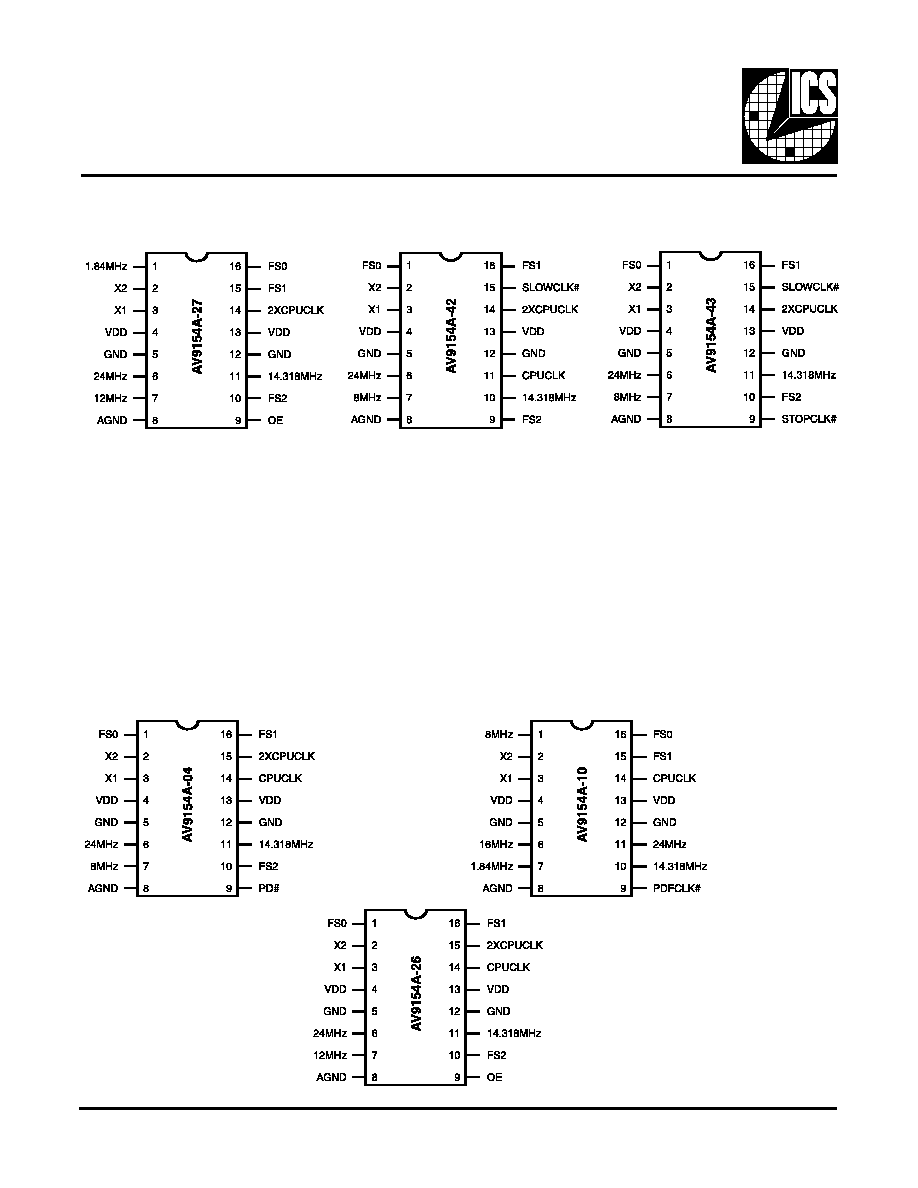
Pin Configuration
16-Pin PDIP or SOIC
AV9154A-27
16-Pin PDIP or SOIC
AV9154A-42
16-Pin PDIP or SOIC
AV9154A-43
Description of new pin:
SLOWCLK# forces 2XCPUCLK
output to ramp smoothly to
8MHz and CPUCLK output to 4
MHz when pulled low.
Description of new pis:
SLOWCLK# forces 2XCPUCLK
output to ramp smoothly to
8MHz when pulled low.
STOPCLK# provides gilitch-
free stop of the 2XCPUCLK
output when pulled low. When
raised back high, the
2XCPUCLK output clock
resumes full speed operation
(no clock frequency ramp up
since the internal VCO is not
stopped).
16-Pin PDIP or SOIC
9154-04
16-Pin PDIP or SOIC
9154-26
16-Pin PDIP or SOIC
9154-10

3
AV9154A
Stop Clock Feature
The ICS9154A-43 incorporates a unique stop clock
feature compatible with static logic processors. When
the stop clock pin goes low, the 2XCPUCLK will go
low after the next occurring falling edge. When
STOPCLK again goes high, 2XCPUCLK resumes on
the next rising edge of the internal clock. This feature
enables fast, glitch-free starts and stops of the
2XCPUCLK and is guaranteed that the CPU does not
receive any short period clocks.

4
AV9154A
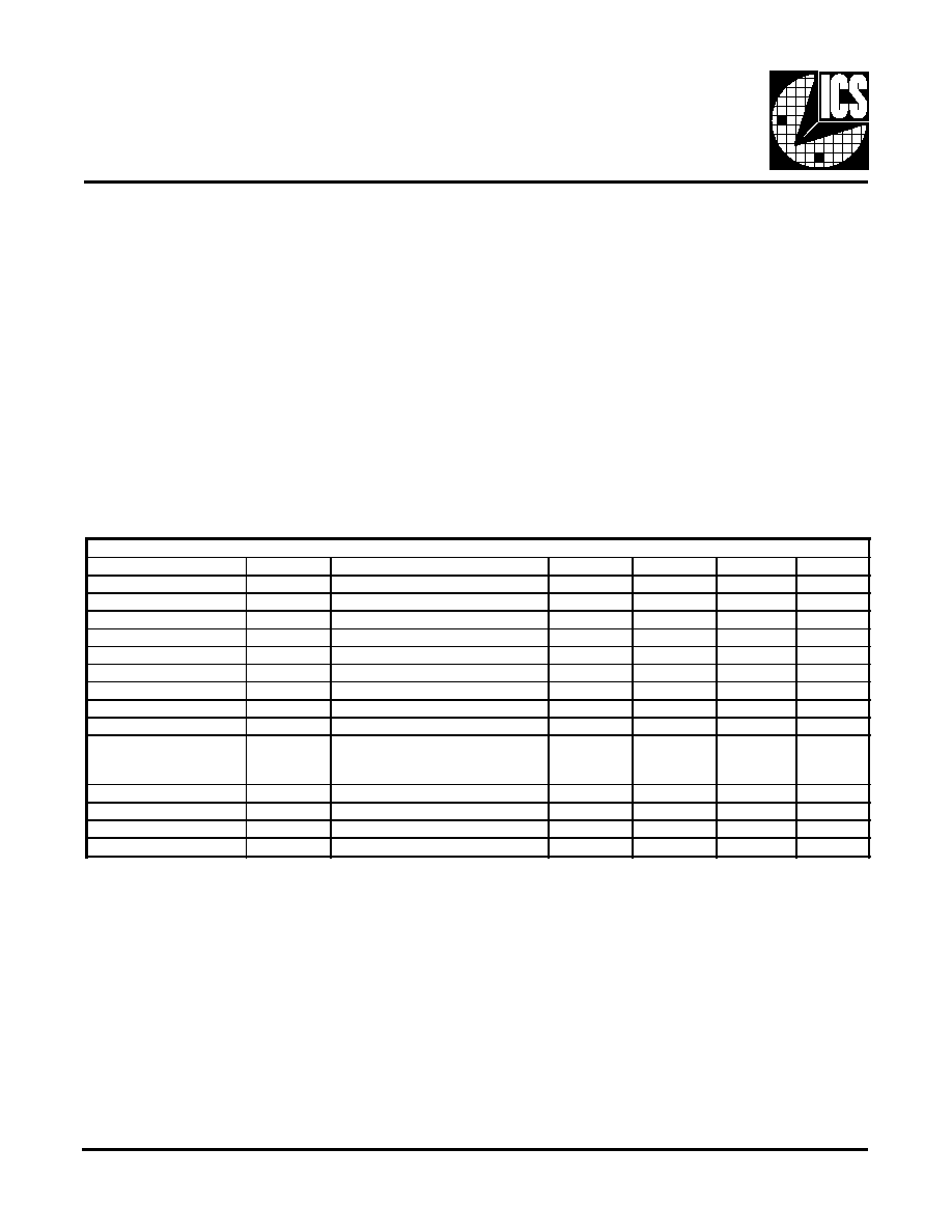
Pin Descriptions
Frequencies based upon 14.318 MHz input)
Note:
Internal Pull-up Resistors.
* -04 and -10 have no pull-ups or frequency select pins
** -10 has no pull-up or Pin 9 PDFCLK
PIN NUMBER
PIN NAME
TYPE
DESCRIPTION
-4
-10
-26
-27
-42
-43
4
4
4
4
4
4
VDD
P
Digital power (3.3 or 5V).
13
13
13
13
13
13
VDD
P
Digital power (3.3 or 5V).
5
5
5
5
5
5
GND
P
Digital ground.
12
12
12
12
12
12
GDD
P
Digital ground.
8
8
8
8
8
8
AGND
P
Analog ground.
1
16
1
16
1
1
FS0
I
Frequency select 0 for CPU clock
(has internal pull-up).*
16
15
16
15
16
16
FS1
I
Frequency select 1 for CPU clock
(has internal pull-up).*
10
-
10
10
9
10
FS2
I
Frequency select 2 for CPU clock
(has internal pull-up).*
-
-
9
9
-
-
OE
I
Tristates outputs when low (has internal pull-up).*
-
-
-
-
15
15
SLOWCLK#
I
Slows 2XCPU clock to 8 MHz (active low)
(has internal pull-up).
-
-
-
-
-
9
STOPCLK#
I
Stops 2XCPU clock glitch-free (active low)
(has internal pull-up).
3
3
3
3
3
3
X1
I
Crystal In.
2
2
2
2
2
2
X2
O
Crystal Out.
11
10
11
11
10
11
14.318 MHz
O
14.318 MHz reference clock output.
-
7
1
-
-
1.84 MHz
O
1.84 MHz (comm) clock output.
6
11
6
6
6
6
24 MHz
O
24 MHz (floppy disk) clock output.
-
6
-
-
-
-
16 MHz
O
16 MHz clock output.
-
-
7
7
-
-
12 MHz
O
12 MHz keyboard clock output.
7
1
-
-
7
7
8 MHz
O
8 MHz keyboard clock output.
14
14
14
-
11
-
CPUCLK
O
CPU clock output.
15
-
15
14
14
14
2XCPUCLK
O
2X CPU clock output.
9
-
-
-
-
-
PD#
I
Power-Down All (active low) (has internal pull-up).
-
9
-
-
-
-
PDFCLK#
I
Power-Down Fixed Clock
(1.84, 8, 16, 24) (active low).**

5
AV9154A
* These selections only operate at 5 V.
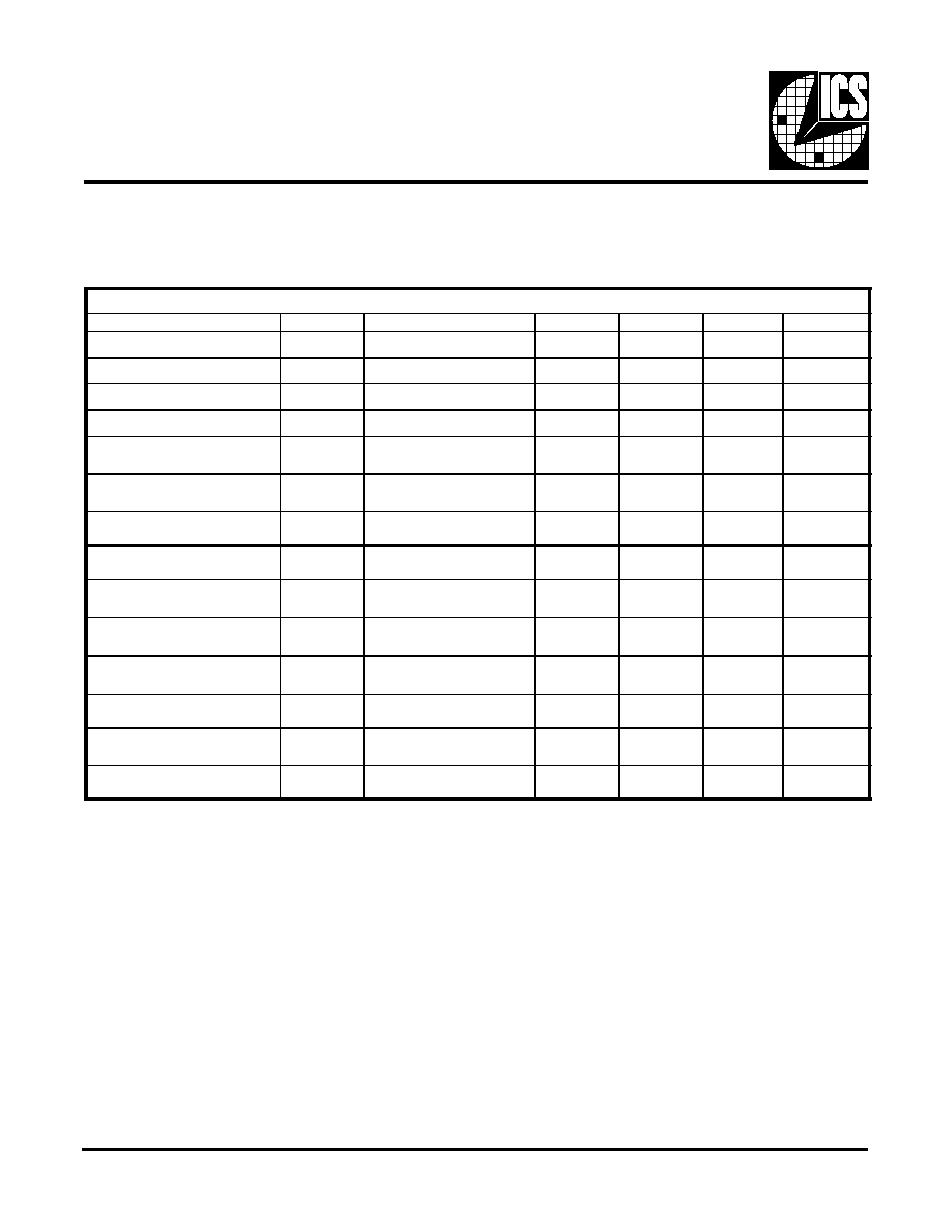
Actual Frequencies
(using 14.318 MHz in put, all frequencies in MHz)
FS2
FS1
FS0
-27
2CPUCLK
-42
-43
2XCPUCLK
CPUCLK
2XCPUCLK
0
0
0
75.17*
16.00
8.00
16.00
0
0
1
31.94
40.09
20.05
40.09
0
1
0
60.14
33.41
16.71
33.41
0
1
1
40.09
25.06
12.55
25.06
1
0
0
50.11
60.14
30.07
60.14
1
0
1
66.48
20.05
10.03
20.05
1
1
0
80.18*
66.48
33.24
66.48
1
1
1
51.90
50.11
25.06
50.11
Clock Tables
(using 14.318 MHz input, all frequencies in MHz)
FS2
FS1
FS0
-27
2XCPUCLK
-42
-43
2XCPUCLK
2XCPUCLK
CPUCLK
^
0
0
0
75*
16
8
16
0
0
1
32
40
20
40
0
1
0
60
33.33
16.67
33.33
0
1
1
40
25
12.50
25
1
0
0
50
60
30
60
1
0
1
66.66
20
10
20
1
1
0
80*
66.66
33.33
66.66
1
1
1
52
50
25
50
Fixed Clock Output
Actual Frequencies
(using 14.318 MHz input,
all freqencies in MHz)
14.318
1.84
24.0
12.0
8.0
Clock Tables in MHz
for -04 and -10
(using 14.318 MHz input ,
all frequencies in MHz)
FS(3:0)
-04
-10
2XCPU
CPU
CPUCL-
K
0
100*
50*
PDCPU
1
80*
40*
40
2
66.6
33.3
50
3
50
25
66.6
4
40
20
-
5
32
16
-
6
24
12
-
7
16
8
-
-
Clock Table for AV9154A-26
(using 14.318 MHz input all frequencies in
MHz)
FS(2:0)
2XCPU
(MHz)
CPUCLK
(MHz)
0
100.23*
50.11
1
80.18*
40.09
2
66.48*
33.24
3
50.11
25.06
4
40.09
20.05
5
32.22
16.11
6
24.23
12.12
7
15.75
7.88
6
AV9154A
Absolute Maximum Ratings
V
DD
referenced to GND ........................................................................... 7.0 V
Voltage on I/O pins referenced to GND ..... GND - 0.5 V to VDD + 0.5 V
Operating Temperature under bias .............................................. 0 to +70 ∫C
Power Dissipation ................................................................................... 0.5 W
Storage Temperature ............................................................... -40 to +150 ∫C
Stresses above those listed under Absolute Maximum Ratings may cause permanent damage to the device. These ratings are stess
specifications only and functional operation of the device at these or any other conditions above those listed in the operational
sections of the specifications is not implied. Exposure to absolute maximum rating conditions for extended periods may affect
product reliability.
V
DD
= 3.3 V ± 10%, T
A
= 0 - 70
o
C unless otherwise stated
Electrical Characteristics at 3.3 V
Notes:
1. Parameter is guaranteed by design and characterization.
DC Characteristics
PARAMETER
SYMBOL
TEST CONDITIONS
MIN
TYP
MAX
UNITS
Input Low Voltage
VIL
-
-
0.2 VDD
V
Input High Voltage
VIH
0.7 V
-
-
V
Input Low Current
IIL
VIN
= 0V (pull-up pin)
-
2.5
7.0
A
Input High Current
IIH
V
IN
= VDD
-5.0
-
5.0
A
Output Low Voltage
VOL
IOL = 6mA
-
0.05 VDD
0.1 VDD
V
Output High Voltage
1
VOH
IOH = -4mA
0.85 VDD
0.94 VDD
-
V
Output Low Current
1
IOL
VOL
= 0.2VDD
15.0
24
-
mA
Output High Current
1
IOH
VOH = 0.7VDD
-
-13
-8.0
mA
Supply Current
IDD
unloaded, 60 MHz
-
16
34
mA
O u t p u t F r e q u e n c y
C ha ng e o ve r Su p pl y
and Temperature
1
FD
With respect to typical frequency
-
0.002
0.01
%
Short circuit current
1
ISC
each output clock
20
30
-
mA
Input Capacitance
1
CI
except X1, X2
-
-
10
pF
Load Capacitance
1
CL
pins X1, X2
-
20
-
pF
Pull-up Resistor
1
Rpu
at VDD - 0.5V
-
620
900
k ohm

7
AV9154A
Electrical Characteristics at 3.3 V
V
DD
= 3.3 V ± 10%, T
A
= 0 - 70
o
C unless otherwise stated
Notes:
1. Parameter is guaranteed by design and characterization. Not subject to production testing.
AC Characteristics
PARAMETER
SYMBOL
TEST CONDITIONS
MIN
TYP
MAX
UNITS
Input Clock Rise Time
1
t
ICr
-
-
20
ns
Input Clock Fall Time
1
t
ICf
-
-
20
ns
Rise time, 20% to 80%
V
DD
1
t
r
15pF load
-
2.2
3.5
ns
Fall time, 80% to 20%
V
DD
1
t
f
15pF load
-
1.2
2.5
ns
Duty cycle at 50% V
DD
1
d
t
15pF load
40/60
48/52
60/40
%
Duty cycle, reference
clocks
1
d
t
15pF load
50/65
43/57
65/50
%
Jitter, one sigma, 20-66
MHz clocks
1
t
j1s
10,000 cycles
-
100
200
ps
Jitter, one sigma, clocks
below 20 MHz
1
t
jls
10,000 cycles
-
1.0
2.0
%
Jitter, absolute, 20-66
MHz clocks
1
t
jab
10,000 cycles
-350
-
350
ps
Jitter, absolute, clocks
below 20 MHz
1
t
jab
10,000 cycles
-
1.5
4.0
%
Input Frequency
1
f
in
2
14.318
32
MHz
Maximum Output
Frequency
1
f
out
70
-
-
MHz
Clock skew between CPU
and 2XCPU outputs
1
T
sk
AV9154A-42
-
220
500
ps
Power-up Time
1
t
tPO
off to 50 MHz
-
6
12
ms
Frequency Transition
Time
1
t
ft
from 8 to 50 MHz
-
4.5
10
ms
8
AV9154A
DC Characteristics
PARAMETER
SYMBOL
TEST CONDITIONS
MIN
TYP
MAX
UNITS
Input Low Voltage
V
IL
V
DD
=5 V
-
-
0.8
V
Input High Voltage
V
IH
V
DD
=5 V
2.0
-
-
V
Input Low Current
I
IL
V
IN
=0 V (pull-up pin)
-
6
15
A
Input High Current
I
IH
V
IN
= V
DD
-5
-
5
A
Output Low Voltage
V
OL
I
OL
= 10 mA
-
0.15
0.4
V
Output High Voltage
1
V
OH
I
OH
= -30 mA
2.4
3.7
-
V
Output Low Current
1
I
OL
V
OL
= 0.8 V
25
45
-
mA
Output High Current
1
I
OH
V
OH
= 2.4 V
-
-53
-35
mA
Supply Current
I
DD
unloaded, 66 MHz
-
25
50
mA
Output Frequency Change
over Supply and Temperature
1
F
D
with respect to typical
frequency
-
0.002
0.01
%
Short circuit current
1
I
SC
each output clock
25
40
-
mA
Input Capacitance
1
C
I
except X1, X2
-
-
10
pF
Load Capacitance
1
C
L
pins X1, X2
-
20
-
pF
Pull-up Resistor
1
R
pu
A + V
DD
-1 V
-
400
700
k ohm
Electrical Characteristics at 5.0 V
Notes:
1. Parameter is guaranteed by design and characterization. Not subject to production testing.
V
DD
= +5 ± 10% V, T
A
= 0 - 70
o
C unless otherwise stated

9
AV9154A
Electrical Characteristics at 5.0 V
V
DD
= +5 ±10% V, T
A
= 0 - 70
o
C unless otherwise stated
AC Characteristics
PARAMETER
SYMBOL
TEST CONDITIONS
MIN
TYP
MAX
UNITS
Input Clock Rise Time
1
t
ICr
-
-
20
ns
Input Clock Fall Time
1
t
ICf
-
-
20
ns
Output Rise time, 0.8 to
2.0V
1
t
r
15pF load
-
1.5
2
ns
Rise time, 20% to 80% V
1
t
r
15pF load
-
2.0
3
ns
Output Fall time, 2.0 to
0.8V
1
t
f
15pF load
-
0.5
1.5
ns
Fall time, 80% to 20% V
1
t
f
15pF load
-
2.0
3.0
ns
Duty cycle at 1.4V
1
d
t
15pF load, V
DD
= 5V±5%
45/55
48/52
55/45
%
Duty cycle, reference
clocks
1
d
t
15 pF load
40/65
43/57
65/40
%
Jitter, one sigma, 20 MHz-
80 MHz clocks
1
t
j1s
10,000 cycles
-
70
140
ps
Jitter, one sigma, clocks
below 20 MHz
1
t
jls
10,000 cycles
-
0.8
2.0
%
Jitter, absolute, 20 MHz-
80 MHz clocks
1
t
jab
10,000 cycles
-250
-
250
ps
Jitter, absolute, clocks
below 20 MHz
1
t
jab
10,000 cycles
-
1.0
3.0
%
Input Frequency
f
in
2
14.318
32
MHz
Maximum Output
Frequency
1
f
out
140
-
-
MHz
Clock skew between CPU
and 2XCPU outputs
1
T
sk
AV9154A-42
-
140
400
ps
Power-up Time
1
t
tPO
to 80 MHz
-
8
15
ms
Frequency Transition
Time
1
t
ft
from 8 to 66.66 MHz
-
6.5
12
ms
Notes:
1. Parameter is guaranteed by design and characterization. Not subject to production testing.

10
AV9154A
Example:
ICS XXXX-PPP M X#W
Lead Count & Package Width
Lead Count=1,2, or 3 digits
W=0.3" SOIC or 0.6" DIP; None=Standard Width
Package Type
N=DIP (Plastic),
S=SOIC
Device Type (consists of 3 or 4-digit numbers)
Prefix
ICS, AV=Standard Device; GSP=Genlock device
Pattern Number (2 or 3-digit number for parts with ROM-code patterns)
0.765
0.130
0.060
0.018
0.100
0.130
0 ~ 5∫
0.010
0.260
0.360
0.015min
0.325
16-Pin PDIP Package
0.390
0.031
0.024
0.016
0.050
0.063
0.006±0.004
0.238
0.154
0.008
0.015
0.025
16-Pin SOIC Package
Ordering Information
AV9154A-27CN16
AV9154A-42CN16
AV9154A-43CN16
AV9154A-04CN16
AV9154A-10CN16
AV9154A-26CN16
AV9154A-27CS16
AV9154A-42CS16
AV9154A-43CS16
AV9154A-04CS16
AV9154A-10CS16
AV9154A-26CS16