 | –≠–ª–µ–∫—Ç—Ä–æ–Ω–Ω—ã–π –∫–æ–º–ø–æ–Ω–µ–Ω—Ç: 79RC64575 | –°–∫–∞—á–∞—Ç—å:  PDF PDF  ZIP ZIP |

1 of 28
December 14, 2001
2001 Integrated Device Technology, Inc.
DSC 5607
IDT and the IDT logo are registered trademarks of Integrated Device Technology, Inc.
Advanced 64-bit
Microprocessors
Product Family
Features
Features
Features
Features
x
High-performance 64-bit embedded Microprocessor
≠ 250MHz operating frequency
≠ >330 Dhrystone MIPS performance
≠ 300MFLOPS/s floating-point performance
≠ Up to 125 million multiply accumulate per second (MAC/s)
≠ MIPS-IV Instruction Set Architecture (ISA), with integer DSP
and 3-operand integer multiply extensions
≠ Limited dual-issue microarchitecture
x
Compatible with RC4640 and RC32364 DSP extensions
≠ DSP Extensions, for consumer applications
≠ 2-cycle repeat rate, on atomic Multiply-add
≠ Multiply-subtract (MSUB) support, for complex number
processing
≠ Count-leading-zero/one support, for string searches and
normalization
x
High-performance on-chip cache subsystem
≠ 32kB, two-set associative instruction cache (I-cache)
≠ 32kB, two-set associative data cache (D-cache)
≠ Write-through and write-back data cache operations
≠ High-performance cache-ops, bandwidth management
x
I-cache and D-cache locking capability (per line), provides
improved real-time support
x
Joint TLB on-chip, for virtual-to-physical address mapping
x
Big- or Little-endian capability
x
RC5000 compatible memory management
≠ On-chip 48-entry, 96-page TLB, for advanced operating
system support
≠ Compatible with major operating systems:
Windows
Æ
CE, VxWorks, and others
x
Bus compatible with IDT 64-bit microprocessor families
≠ Pipeline runs at 2 to 8 times the bus frequency
≠ Bus speeds to 125MHz
≠ 32-bit bus option, for lower cost systems
≠ Enhanced timing protocol for SyncDRAM systems (compatible
with IDT79RC64474/475)
x
RC64574:
≠ 32-bit SysAd bus, for low-cost systems
≠ Pin compatible with RC4640 and RC64474
≠ 128-pin QFP package
x
RC64575:
≠ 64-bit SysAd bus interface
≠ Pin compatible with RC4650 and RC64475
≠ 208-pin QFP package
x
Industrial temperature range support
x
JTAG Boundary Scan Interface
x
2.5V operation with 3.3V tolerant I/O
Block
Block
Block
Block Di
Di
Di
Diagra
agra
agra
agram
m
m
m
Figure 1 RC64574/RC64575 Block Diagram
64-bit
Integer
DSP
Accelerator
Execution Unit
666 MFIOPS
Floating-Point
Accelerator
PLL
Dual-Issue Instruction Fetch Unit
Primary Cache Controller
RC5000
Compatible
System Control
Coprocessor
48-entry
96-page
TLB
32kB
2 set-associative
Instruction
Cache
32kB
2 set-associative
Data
Cache
64-bit/32-bit
RC64474/475 Compatible
System Interface
ClkIn
(Lockable)
(Lockable)
IEEE 1284
79RC64574
TM
79RC64575
TM

2 of 28
December 14, 2001
79RC64574TM 79RC64575TM
Device Overview
Device Overview
Device Overview
Device Overview
1
1
1
1
IDT's 79RC64574/575 processors serve a wide range of perfor-
mance-critical embedded applications that include high-end internet-
working systems, digital set-top boxes, web browsers, color printers,
and graphics terminals.
The RC64574/575 allow a socket compatible upgrade path for IDT's
RC4640/50 and RC64474/475 processors. This unprecedented upgrad-
ability allows a 2:1 range of frequencies; 4:1 range of cache size; 15:1
range of floating-point; and 4:1 range of DSP performance in a single
socket.
With special emphasis on system bandwidth, floating- point and DSP
operations, the RC64574/575 have been optimized for high-perfor-
mance applications through the integration of high-performance compu-
tational units and a high-performance memory hierarchy. The result is a
low-cost CPU that is capable of more than 330 Dhrystone MIPS.
Through the RC64574/64575 processors IDT offers:
x
High-performance upgrade paths to existing embedded
customers in the internetworking, office automation and
visualization markets.
x
Significant floating-point performance improvements over
currently available, moderately priced MIPS CPUs.
x
Performance improvements through the use of the MIPS-IV ISA.
x
High-performance DSP acceleration
1.
Detailed system operation information is provided in the RC64574/RC64575
user's manual.
Instruction Issue Mechanism
Instruction Issue Mechanism
Instruction Issue Mechanism
Instruction Issue Mechanism
The RC64574 and RC64575 are limited dual-issue super-scalar
machines that use a traditional 5-stage integer pipeline, as shown in the
pipeline diagram on Page 3. For multi-issue operations, these devices
recognize the following two general classes of instructions:
x
Floating-point ALU
x
All others
Such a broad separation of instruction classes insure that there are
no data dependencies to restrict multi-issue performance. As they are
brought on-chip, these instruction classes are pre-decoded by the
RC64574/575, and the class information is then stored in the instruction
cache. Assuming there are no pending resource conflicts, the devices
can issue one instruction per class per pipeline clock cycle.
However, longer latency resources--in either the floating-point ALU
(for example, division or square root instructions) or integer unit (such as
multiply)--can restrict the issue of instructions. Note that these proces-
sors do not perform out-of-order or speculative execution; instead, the
pipeline slips until the required resource becomes available.
On dual-issue instruction pairs, there are no alignment restrictions,
and the RC64574/575 fetch two instructions from the cache per cycle.
Thus, for optimal performance, compilers should attempt to align branch
targets to allow dual-issue on the first target cycle, because the instruc-
tion cache only performs aligned fetches.
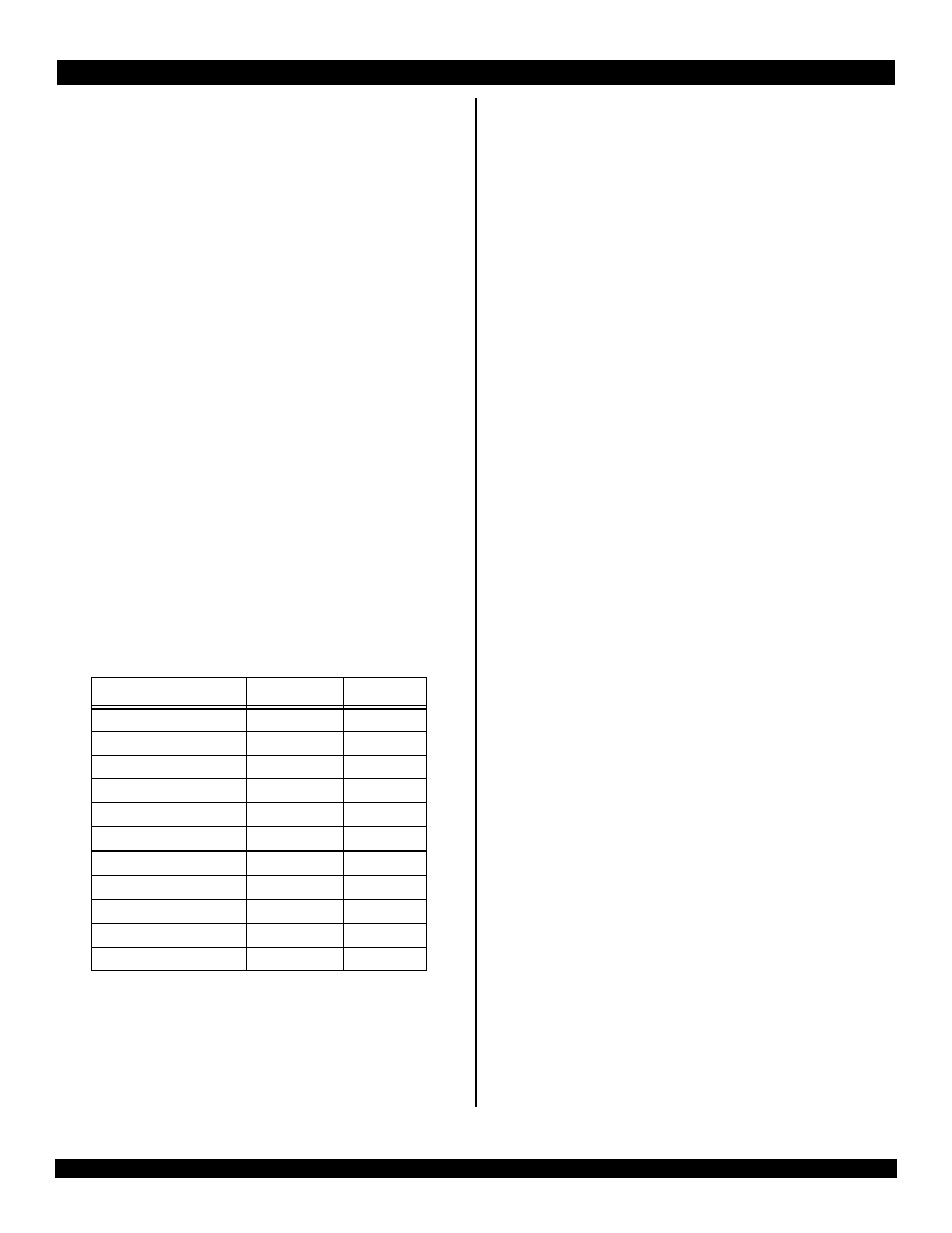
RISCore4000/RISCore5000 Family of Socket Compatible Processors
RISCore4000/RISCore5000 Family of Socket Compatible Processors
RISCore4000/RISCore5000 Family of Socket Compatible Processors
RISCore4000/RISCore5000 Family of Socket Compatible Processors
32-bit External Bus Processors
64-bit External Bus Processors
RC4640
RC64474
RC64574
RC4650
RC64475
RC64575
CPU
64-bit RISCore4000 w/
DSP extensions
64-bit RISCore4000
64-bit RISCore5000 w/
DSP extensions
64-bit RISCore4000 w/
DSP extensions
64-bit RISCore4000
64-bit RISCore5000 w/
DSP extensions
Performance
>350MIPS
>330MIPS
>330MIPS
>350MIPS
>330MIPS
>330MIPS
FPA
89 mflops, single preci-
sion only
125 mflops, single and
double precision
666 mflops, single and
double precision
89 mflops, single preci-
sion only
125 mflops, single and
double precision
666 mflops, single and
double precision
Caches
8kB/8kB, 2-way,
lockable by set
16kB/16kB, 2-way,
lockable by set
32kB/32kB, 2-way,
lockable by line
8kB/8kB, 2-way,
lockable by set
16kB/16kB, 2-way,
lockable by set
32kB/32kB, 2-way,
lockable by line
External Bus
32-bit
32-bit, Superset pin
compatible w/RC4640
32-bit, Superset pin
compatible w/RC4640,
RC64474
32- or 64-bit
32-or 64-bit, Superset
pin compatible w/
RC4650
32-or 64-bit, Superset
pin compatible w/
RC4650, RC64475
Voltage
3.3V
3.3V
2.5V
3.3V
3.3V
2.5V
Frequencies
100-267 MHz
180-250 MHz
200-250 MHz
100-267 MHz
180-250 MHz
250 MHz
Packages
128 PQFP
128 QFP
128 QFP
208 QFP
208 QFP
208 QFP
MMU
Base-Bounds
96 page TLB
96 page TLB
Base-Bounds
96 page TLB
96 page TLB
Key Features
Cache locking, on-chip
MAC, 32-bit external
bus
Cache locking, JTAG,
syncDRAM mode, 32-bit
external bus
Cache locking, JTAG,
syncDRAM mode, 32-bit
external bus
Cache locking, on-chip
MAC, 32-bit & 64 bit
bus option
Cache locking, JTAG,
syncDRAM mode, 32-
64- bit bus option
Cache locking, JTAG,
syncDRAM mode, 32-
64- bit bus option
Table 1 RISCore4000/RISCore5000 Processor Family
3 of 28
December 14, 2001
79RC64574TM 79RC64575TM
Instruction Set Architecture
Instruction Set Architecture
Instruction Set Architecture
Instruction Set Architecture
The RC64574/575 implement a superset of the MIPS-IV 64-bit ISA,
including CP1 and CP1X functional units and their instruction set. Both
32- and 64-bit data operations are performed by utilizing thirty-two
general purpose 64-bit registers (GPR) that are used for integer opera-
tions and address calculation. The complete on-chip floating-point co-
processor (CP1)--which includes a floating-point register file and execu-
tion units--forms a "seamless" interface, decoding and executing
instructions in parallel with the integer unit.
CP1's floating-point execution units support both single and
double precision arithmetic--as specified in the IEEE Standard 754--
and are separated into a multiply unit and a combined add/convert/
divide/square root unit. Overlap of multiplies and add/subtract is
supported, and the multiplier is partially pipelined, allowing the initiation
of a new multiply instruction every fourth pipeline cycle. The floating-
point register file is made up of thirty-two 64-bit registers. The floating-
point unit can take advantage of the 64-bit wide data cache and issue a
co-processor load or store doubleword instruction in every cycle.
The system control coprocessor (CP0) registers are also incorpo-
rated on-chip and provide the path through which the virtual memory
system's page mapping is examined and changed, exceptions are
handled, and any operating mode selections are controlled. A secure
user processing environment is provided through the user, supervisor,
and kernel operating modes of virtual addressing to system software.
Bits in a status register determine which of these modes is used.
Integer Pipeline
Integer Pipeline
Integer Pipeline
Integer Pipeline
The integer instruction execution speed is tabulated--in number of
pipeline clocks--as follows:
Table 2 Integer Instruction Execution Speed
To insure that the maximum frequency of operation is not limited by
the speed of the multiplier unit, a "fast multiply" disable reset mode bit
(see Table 2) is featured. When this bit is asserted, each multiply opera-
tion shown in Table 1 has its latency and repeat rate increased by one
cycle.
Operation
Latency
Repeat
Load
2
1
Store
2
1
MULT/MULTU
4
3
DMULT/DMULTU
6
5
DIV/DIVU
36
36
DDIV/DDIVU
68
68
MAD/MADU
3
2
MSUB/MSUBU
4
3
Other Integer ALU
1
1
Branch
2
2
Jump
2
2
Load and branch latencies are minimized by the short pipeline of the
RC64574/575, and the caches contain special logic that will allow any
combination of loads and stores to execute in back-to-back cycles
without requiring pipeline slips or stalls, assuming the operation does
not miss in the cache.
Computational Units
Computational Units
Computational Units
Computational Units
The RC64574/575 implement a full, single-cycle 64-bit arithmetic
logic unit (ALU), for Integer ALU functions other than multiply and
divide. Bypassing is used to support back-to-back ALU operations at the
full pipeline rate, without requiring stalls for data dependencies.
To allow the longer latency operations to run in parallel with other
operations, the Integer Multiply/Divide unit of the RC64574/ 575 is
separated from the primary ALU. The pipeline stalls only if an attempt to
access the HI or LO registers is made before an operation completes.
The Floating-point ALU unit is responsible for all of the CP1/CP1X
ALU operations--other than DIV/SQRT operations--and is pipelined to
allow a single-cycle repeat rate for single-precision operations.
The Floating-point DIV/SQRT unit is separated from the floating-
point ALU, to ensure that these longer latency operations do not prevent
the issue of other floating-point operations. Separate logical units are
also provided on the RC64574/575 to implement load, store, and branch
operations.
Intended to enhance the performance of DSP algorithms such as fast
fused multiply-adds, multiply-subtracts and three operand multiply oper-
ations, new instructions have been added over and above the MIPS-IV
ISA.
System Interfaces
System Interfaces
System Interfaces
System Interfaces
The RC64575 supports a 64-bit system interface that is pin and
bus compatible with the RC4650 and RC64475 system interface. The
system interface consists of a 64-bit Address/Data bus with eight parity-
check bits and a 9-bit command bus.
During 64-bit operation, RC64575 system address/data (SysAD)
transfers are protected with an 8-bit parity check bus, SysADC. When
initialized for 32-bit operation, the RC64575's SysAD can be viewed as a
32-bit multiplexed bus that is protected by four parity-check bits.
The RC64574 supports a 32-bit system interface that is pin and
bus compatible with the RC4640 and RC64474. During 32-bit operation,
SysAD transfers are performed on a 32-bit multiplexed bus (SysAD
31:0) that is protected by 4 parity check bits (SysADC 6:0).
Writes to external memory--whether they are cache miss write-
backs, stores to uncached or write-through addresses--use the on-chip
write buffer. The write buffer holds a maximum of four 64-bit addresses
and 64-bit data pairs. The entire buffer is used for a data cache write-
back and allows the processor to proceed in parallel with memory
updates.
Included in the system interface are six handshake signals:
RdRdy*, WrRdy*, ExtRqst*, Release*, ValidOut*, and ValidIn*; six inter-
rupt inputs, and a simple timing specification that is capable of trans-
4 of 28
December 14, 2001
79RC64574TM 79RC64575TM
ferring data between the processor and memory at a peak rate of
1000MB/sec. A boot-time selectable option to run the system interface
as 32-bits wide--using basically the same protocols as the 64-bit
system--is also supported.
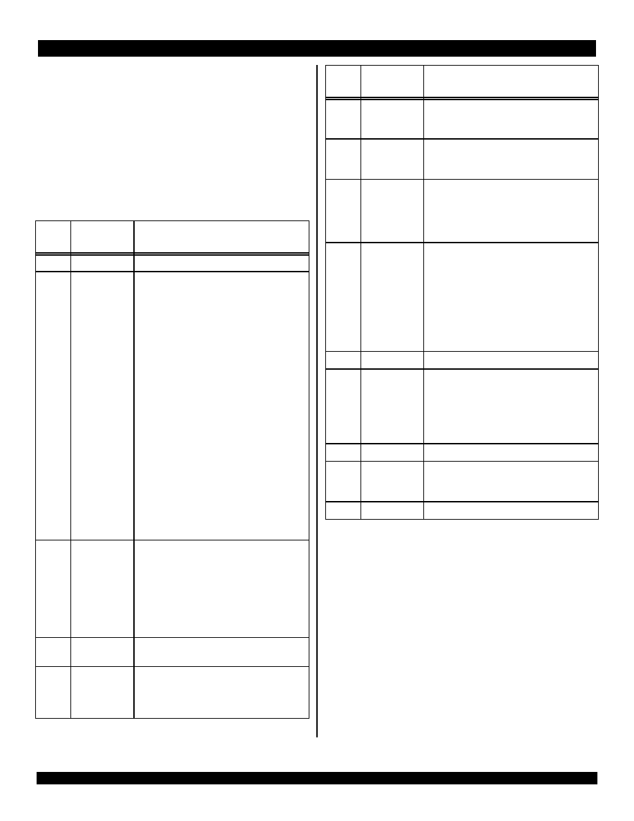
A boot-time mode control interface initializes fundamental
processor modes and is a serial interface that operates at a very low
frequency (SysClock divided by 256). This low-frequency operation
allows the initialization information to be kept in a low-cost EPROM;
alternatively, the twenty-or-so bits could be generated by the system
interface ASIC or a simple PAL. The boot-time serial stream is shown in
Table 3.
Serial
Bit Description
Value & Mode Setting
0
Reserved
Must be set to 0.
1:4
Transmit-data-
pattern.
Bit 4 is MSB
64-bit bus width:
0: DDDD
1: DDxDDx
2: DDxxDDxx
3: DxDxDxDx
4: DDxxxDDxxx
5: DDxxxxDDxxxx
6: DxxDxxDxxDxx
7: DDxxxxxxDDxxxxxx
8: DxxxDxxxDxxxDxxx
9-15: Reserved. Must not be selected.
32-bit bus width:
0: WWWWWWWW
1: WWxWWxWWxWWx
2: WWxxWWxxWWxxWWxx
3: WxWxWxWxWxWxWxWx
4: WWxxxWWxxxWWxxxWWxxx
5: WWxxxxWWxxxxWWxxxxWWxxxx
6: WxxWxxWxxWxxWxxWxxWxxWxx
7: WWxxxxxxWWxxxxxxWWxxxxxxWWxxxxxx
8: WxxxWxxxWxxxWxxxWxxxWxxxWxxxWxxx
9-15: Reserved. Must not be selected.
5:7
PClock-to-
SysClk-Ratio.
Bit 7 is MSB
0: 2
1: 3
2: 4
3: 5
4: 6
5: 7
6: 8
7: Reserved
8
Endianness
0: Little endian
1: Big endian
9:10
Non-block write
Mode. Bit 10 is
MSB
00: R4400 compatible
01: Reserved
10: Pipelined-Write-Mode
11: Write-Reissue-Mode
Table 3 Boot-time Mode Stream (Page 1 of 2)
The clocking interface allows the CPU to be easily mated with
external reference clocks. The CPU input clock is the bus reference
clock and can be between 33 and 125MHz. An on-chip phase-locked-
loop (PLL) generates the pipeline clock (PClock) through multiplication
of the system interface clock by values of 2,3,4,5,6,7 or 8, as defined at
system reset. This allows the pipeline clock to be implemented at a
significantly higher frequency than the system interface clock. The
RC64574/575 support both single data (one byte through full CPU bus
width) and 8-word block transfers on the SysAD bus.
The RC64574/575 implement additional write protocols that
double the effective write bandwidth. The write re-issue has a repeat
rate of 2 cycles per write. Pipelined writes have the same 2-cycle per
write repeat rate, but can issue an additional write after WrRdy* de-
asserts.
11
TimerIntEn
Timer interrupt settings:
0: Enable Timer Interrupt on Int(5)
1: Disable Timer Interrupt on Int(5)
12
System Interface
Bus Width.
Interface bus width control settings:
0: 64-bit system interface
1: 32-bit system interface
13:14
Drv_Out
Bit 14 is MSB
Slew rate control of the output drivers:
10: 100% strength (fastest)
11: 83% strength
00: 67% strength
01: 50% strength (slowest)
15:17
Write address to
write data delay.
From 0 to 7 SysClk cycles:
0: AD...
1: AxD...
2: AxxD...
3: AxxxD...
4: AxxxxD...
5: AxxxxxD...
6: AxxxxxxD...
7: AxxxxxxxD...
18
Reserved
User must select `0'
19
Extend
Multiplication
Repeat Rate.
Initial setting of the "Fast Multiply" bit.
0: Enable Fast Multiply
1: Do not Enable Fast Multiply
Note: For pipeline speeds >250MHz, this bit must
be set to `1'.
20:24
Reserved
User must select `0'
25:26
System
configuration
identifier.
Software visible in processorConfig[21:20]
0: Config[21:20] = Mode Bit [25:26]
Must be set to 0.
27:256
Reserved
User must select `0'
Serial
Bit Description
Value & Mode Setting
Table 3 Boot-time Mode Stream (Page 2 of 2)

5 of 28
December 14, 2001
79RC64574TM 79RC64575TM
Choosing a 32- or 64-bit wide system interface dictates whether a
cache line block transaction requires 4 double word data cycles or 8
single word cycles as well as whether a single data transfer--larger than
4 bytes--must be divided into two smaller transfers.
As shown in Table 3, the bus delay can be defined as 0 to 7
SysClock cycles and is activated and controlled through mode bit
(17:15) settings selected during the reset initialization sequence. The
`000' setting provides the same write operations timing protocol as the
RC4640, RC4650, and RC5000 processors.
To facilitate discrete interface to SyncDRAM, the RC64574/575 bus
interface is enhanced during write cycles with a programmable delay
that is inserted between the write address and the write data (for both
block and non-block writes).
Board-level testing during Run-Time mode is facilitated through the
full JTAG boundary scan facility. Five pins--TDI, TDO, TMS, TCK,
TRST*--have been incorporated to support the standard JTAG inter-
face.
The RC64574/575 devices offer a direct migration path for designs
that are based on IDT's RC4640/RC4650 and RC64474/RC64475
processors
2
, through full pin and socket compatibility. Full 64-bit-family
software and bus protocol compatibility ensures the RC64574/575
processors access to an existing market and development infrastruc-
ture, allowing quicker time to market.
Development Tools
Development Tools
Development Tools
Development Tools
An array of hardware and software tools is available to assist system
designers in the rapid development of RC64574/575 based systems.
This accessibility allows a wide variety of customers to take full advan-
tage of the device's high-performance features while addressing today's
aggressive time-to-market demands.
Cache Memory
Cache Memory
Cache Memory
Cache Memory
To keep the high-performance pipeline of the RC64574/575 full and
operating efficiently, on-chip instruction and data caches have been
incorporated. Each cache has its own data path and can be accessed in
the same single pipeline clock cycle.
The 32kB two-way set associative instruction cache is virtually
indexed, physically tagged, and word parity protected. Because this
cache is virtually indexed, the virtual-to-physical address translation
occurs in parallel with the cache access, further increasing performance
by allowing both operations to occur simultaneously. The instruction
cache provides a peak instruction bandwidth of 2GB/sec at 250MHz.
The 32kB two-way set associative data cache is byte parity
protected and has a fixed 32-byte (eight words) line size. Its tag is
protected with a single parity bit. To allow simultaneous address transla-
tion and data cache access, the D-cache is virtually indexed and physi-
cally tagged. The data cache can provide 8 bytes each clock cycle, for a
peak bandwidth of 2GB/s.
2.
To ensure socket compatibility, refer to Table 8 and Table 9.
To lock critical sections of code and/or data into the caches for quick
access, a per line "cache locking" feature has been implemented.
Once enabled, a cache is said to be locked when a particular piece of
code or data is loaded into the cache and that cache location will not be
selected later for refill by other data.
Power Management
Power Management
Power Management
Power Management
Executing the WAIT instruction enables the processor to enter
Standby mode. The internal clocks will shut down, thus freezing the
pipeline. The PLL, internal timer, and some of the input pins (Int[5:0]*,
NMI*, ExtReq*, Reset*, and ColdReset*) will continue to run. Once in
Standby Mode, any interrupt, including the internally generated timer
interrupt, will cause the CPU to exit Standby Mode.
Thermal Considerations
Thermal Considerations
Thermal Considerations
Thermal Considerations
The RC64574 is packaged in a 128-pin QFP footprint package and
uses a 32-bit external bus, offering the ideal combination of 64-bit
processing power and 32-bit low-cost memory systems. The RC64575
is packaged in a 208-pin QFP footprint package and uses the full 64-bit
external bus. The RC64575 is ideal for applications requiring 64-bit
performance and 64-bit external bandwidth.
Both devices are guaranteed in a case temperature range of 0
∞
to
+85
∞
C for commercial temperature devices and -40
∞
to +85
∞
C for
Industrial temperature devices. Package type, speed (power) of the
device, and air flow conditions affect the equivalent ambient temperature
conditions that will meet these specifications.
Using the thermal resistance from case to ambient (
CA
) of the
given package, the equivalent allowable ambient temperature, T
A
, can
be calculated. The following equation relates ambient and case temper-
atures:
T
A
= T
C
- P *
CA
where P is the maximum power consumption at hot temperature,
calculated by using the maximum I
CC
specification for the device.
Typical values for
CA
at various air flow are shown in Table 4. Note
that the RC64574/575 processor implements advanced power manage-
ment, which substantially reduces the typical power dissipation of the
device.
Revision History
Revision History
Revision History
Revision History
July 22, 1999: Original data sheet.
CA
Airflow (ft/min)
0
200 400 600 800 1000
128 QFP
16
10
9
7
6
5
208 QFP
20
13
10
9
8
7
Table 4 Thermal Resistance (
CA) at Various Airflows