 | –≠–ª–µ–∫—Ç—Ä–æ–Ω–Ω—ã–π –∫–æ–º–ø–æ–Ω–µ–Ω—Ç: NW6006 | –°–∫–∞—á–∞—Ç—å:  PDF PDF  ZIP ZIP |

ENHANCED TYPE II CALLER ID DECODER
WITH STUTTER DIAL TONE DETECTOR
NW6006
The IDT logo is a registered trademark of Integrated Device Technology, Inc
INDUSTRIAL TEMPERATURE RANGE
JULY 2002
©
2002 Integrated Device Technology, Inc.
DSC-6049/3
FEATURES
∑
1200 baud Bell 202 and ITU-T V.23 Frequency Shift Keying
(FSK) Demodulation
∑
Stutter dial tone detection
∑
Compliant with following specifications:
Bellcore GR-30-CORE & SR-TSV-002476
TIA/EIA-716, TIA/EIA-777 Draft
TIA/EIA PN-4195 Draft
British Telecom (BT) SIN227 & SIN242
ETSI ETS 300 778-1 and -2
∑
Bellcore "CPE Alerting Signal (CAS)", British Telecom "Idle State
and Loop State Tone Alert Signal" and ETSI "Dual Tone Alerting
Signal (DT-AS)" detection
∑
Two seperate OP amps with adjustable gain for Tip/Ring and
Telephone Hybrid connections
∑
Monitoring of the stop bit for framing error check
∑
Serial FSK data interface with selectable output of bit stream or 1
byte buffer
∑
FSK carrier detection
∑
3 V or 5 V operation
∑
Low power CMOS with intelligent powerdown mode
∑
Operating temperature range: -40 ∞C to +85 ∞C
∑
Packages available:
NW6006-XS 20 pin SOIC
(where `X' is the revision ID)
DESCRIPTION
The NW6006 device is a single-chip, 3/5 Volt CMOS caller ID with
call waiting detection circuit. It can receive signals following Bellcore
GR-30-CORE & SR-TSV-002476, BT SIN227 & SIN242, and ETSI
ETS 300 788-1/-2 specifications.
The NW6006 provides 1200 baud Bell 202 and ITU-T V.23 FSK
demodulation, detection in stutter dial tone mode and CAS/DT-AS
detection. Two seperate differential input amplifiers allow the device to
be connected with both Tip/Ring and Telephone Hybrid receive pair.
FSK demodulation is implemented only on Tip/Ring, while DT-AS(or
CAS) detection can be on either Tip/Ring or Hybrid Receive. In
addition, NW6006 provides a serial FSK data interface via which the
data can be selected to be processed as a bit stream or extracted
from a 1 byte built-in buffer. An on-chip Stutter Dial Tone Detector is
provided to support the voice mail applications.
The device can be used in feature or cordless phones with voice
mail for BT Calling Line Identity Presentation (CLIP), CCA CLIP and
Bellcore Calling Identity Delivery (CID) systems. It can also be used in
caller ID boxes, modem, fax machines, answering machines,
database query systems and Computer Telephony Integration (CTI)
systems.
VREF
IN1+
OSCOUT OSCIN CB0 CB1 CB2
ST/GT
DR/STD
IN2+
Oscillator
Control Bit Decoder
Bias
Generator
Guard Time
Tone Alert
Detector
FSK
Demodulator
Data/Timing Recovery
+
-
+
-
Mux
PWDN
PWDN
CASEN
CASEN
FSKEN
MODE
GS1EN
GS2EN
FSKEN
MODE
GS1EN
GS2EN
SDTEN
Stutter Dial Tone
Detector
SDTEN
Mux
Figure 1. Block Diagram
FUNCTIONAL BLOCK DIAGRAM
IN1-
GS1
IN2-
GS2
EST
CD/STRDT
DCLK
DATA

2
INDUSTRIAL TEMPERATURE RANGE
NW6006 ENHANCED TYPE II CALLER ID DECODER
WITH STUTTER DIAL TONE DETECTOR
PIN INFORMATION
Figure 2. Pin Assignment
VREF
IN1+
IN1-
GS1
GND
OSCIN
OSCOUT
CB0
DCLK
DATA
IN2+
IN2-
GS2
CB2
CB1
VCC
CD/STRDT
ST/GT
EST
DR/STD
20
19
18
17
16
15
14
13
12
11
1
2
3
4
5
6
7
8
9
10
Name
Type
Pin No.
Description
VREF
O
1
Reference Voltage.
This output is used to bias the input OP amp. It is typically VCC/2.
IN1+
I
2
Non-inverting Input of the gain adjustable Tip/Ring OP amp.
IN1-
I
3
Inverting Input of the gain adjustable Tip/Ring OP amp.
GS1
O
4
Gain Select Output of the gain adjustable Tip/Ring OP amp.
The Tip/Ring signal can be attenuated or amplified at GS1 by adjusting the feedback resistor between GS1 and IN1-.
The FSK signal is always detected by Tip/Ring OP amp while DT-AS(CAS) signal can be detected by either Tip/Ring
or Hybrid OP amp. The OP amp selection is controlled by CB1 and CB2 bits.
GND
-
5
Ground.
OSCIN
I
6
Oscillator Input.
A 3.579545 MHz crystal or ceramic resonator should be connected between this pin and the OSCOUT. It can also
be driven by an external clock source.
OSCOUT
O
7
Oscillator Output.
A 3.579545 MHz crystal or ceramic resonator should be connected between this pin and the OSCIN. When an
external clock drives OSCIN, this pin can be left floating.
CB0
I
8
Control Bit 0 (FSK Data Interface Mode Select).
This pin can select the 3-wire FSK data interface mode. A `0' on this pin indicates interface mode 0; while a `1' on
this pin indicates interface mode 1. (The FSK data interface is consisted of DATA, DCLK and DR/STD pins.)
When CB0 is high and CB1, CB2 are both low, the device is set into the power down state.
DCLK
I/NC
9
Data Clock of the Serial FSK Interface.
In mode 0 (CB0 is low), this pin is unused; In mode 1 (CB0 is high), this pin is an input which clock the FSK data
byte out to the DATA pin.
DATA
O
10
Data Output of the Serial FSK Interface.
In mode 0 (CB0 is low), the FSK serial bit stream is output to the DATA pin directly.
In mode 1 (CB0 is high), the start bit is stripped off, the data byte and the stop bit is stored in a 9-bit buffer. At the
end of each word signaled by the DR/STD pin, the microcontroller should shift the byte out onto the DATA pin by
applying 8 read pulses to the DCLK pin. A 9
th
DCLK pulse will shift out the stop bit for framing error checking.

3
INDUSTRIAL TEMPERATURE RANGE
NW6006 ENHANCED TYPE II CALLER ID DECODER
WITH STUTTER DIAL TONE DETECTOR
Abbreviation Index
CAS
----------------------------------------------------------- CPE Alerting Signal
CDS
---------------------------------------------------------- Caller Display Service
CID
---------------------------------------------------------- Calling Identity Delivery
CIDCW
---------------------------------------------------------- Calling Identity Delivery on Call Waiting
CLIP
---------------------------------------------------------- Calling Line Identity Presentation
CNAM
--------------------------------------------------------- Calling Name Delivery
CND
--------------------------------------------------------- Calling Number Delivery
CNIC
---------------------------------------------------------- Calling Number Identification Circuit
CO
---------------------------------------------------------- Central Office
DT-AS
---------------------------------------------------------- Dual Tone Alert Signal
MEI
---------------------------------------------------------- Multiple Extension Interworking
SDT
---------------------------------------------------------- Stutter Dial Tone
TE
---------------------------------------------------------- Terminal Equipment
PIN INFORMATION (CONTINUED)
Name
Type
Pin No.
Description
DR/STD
O/NC
11
Data Ready or DT-AS Detection Delayed Steering Output.
This pin is active low. When FSK demodulation is enabled, this pin is the Data Ready output. In FSK interface mode 0,
this pin is unused and reads `1'. While in mode 1, this pin is normally high and goes low for half a bit time at the end of
a word. If DCLK starts during DR low, the first rising edge of the DCLK input will return DR to high. In this way, reading
of the first DATA bit can clear the interrupt requested by a low going DR.
When DT-AS detection is enabled, this pin is the Delayed Steering Output. An active low signal on this output indicates
the detection of a `guard time qualified' DT-AS.
EST
O
12
DT-AS Early Steering Output.
This pin is an active high output to indicate the detection of a raw DT-AS signal. It is used with the ST/GT pin and
external components to time qualify the detection.
ST/GT
I/O
13
DT-AS Detection Steering Input/Guard Time Output.
It's a CMOS output and an input of voltage comparator. It is used in conjunction with the EST pin and external
components to time qualify a raw DT-AS signal detection.
If the voltage at this pin is greater than the voltage threshold, DR/STD pin is asserted low to indicate that a DT-AS has
been detected. A voltage less than the threshold enable the device to accept a new DT-AS and return the DR/STD pin
to high.
CD/STRDT
O
14
FSK Carrier Detector or Stutter Dial Tone Detector Output.
This is an active low CMOS output signal to indicate the presence of in-band FSK signal or valid Stutter Dial Tone
signal.
VCC
-
15
3/5 V Power Supply.
CB1
I
16
Control Bit 1 (Function Select 1).
This pin is used with CB2 to select FSK demodulation, Tip/Ring DT-AS/Dial Tone detection, Hybrid DT-AS/Dial Tone
detection with or without Stutter Dial Tone Detection. See Table 1. When CB0 is high, CB1 and CB2 pins are both low,
the device is set into the power down state.
CB2
I
17
Control Bit 2 (Function Select 0).
This pin is used with CB2 to select FSK demodulation, Tip/Ring DT-AS/Dial Tone detection, Hybrid DT-AS/Dial Tone
detection with or without Stutter Dial Tone Detection. See Table 1. When CB0 is high, CB1 and CB2 pins are both low,
the device is set into the power down state.
GS2
O
18
Gain Select Output of the gain adjustable Hybrid OP amp.
The hybrid receive signal can be amplified or attenuated at GS2 by adjusting the feedback resistor between GS2 and
IN2-. When the CPE is off-hook, DT-AS detection of the GS2 signal should be enabled via the CB1 and CB2 pins.
IN2-
I
19
Inverting Input of the gain adjustable Hybrid OP amp.
IN2+
I
20
Non-inverting Input of the gain adjustable Hybrid OP amp.

4
INDUSTRIAL TEMPERATURE RANGE
NW6006 ENHANCED TYPE II CALLER ID DECODER
WITH STUTTER DIAL TONE DETECTOR
FUNCTIONAL DESCRIPTION
CALLER ID SPECS SUPPORTED
The NW6006 is a type II Caller ID device with Call Waiting
capability. It supports Bellcore, BT and ETSI specifications. The major
differences between above specs are as follows (see Fig. 11, Fig. 12
and Fig. 13 for reference):
BELLCORE AND TIA
Bellcore GR-30-CORE and SR-TSV-002476 define the
requirement for the signalling services of Calling Number Delivery
(CND), Calling Name Delivery (CNAM), VMWI (Visual Message
Waiting Indicator) and Calling Identity Delivery on Call Waiting
(CIDCW).
In CND or CNAM service, information of the calling party is
embedded in the silent interval between the first and second ringing.
The NW6006 can detect and demodulate the incoming Bell-202 FSK
data. In CIDCW service, information about an incoming caller is sent
to the subscriber who is engaged in another call. A CPE Alerting
Signal (CAS) indicates that a CIDCW data is incoming. The NW6006
can detect the alerting signal and demodulate the incoming FSK
information which contains CIDCW data. The demodulated data is
output onto the serial interface.
In North America, Telecommunications Industry Association (TIA)
Pin
Name
Description
CB0
FSK Data Interface Mode
Select
0
1
FSK Data Interface Mode 0: FSK bit stream is output directly.
FSK Data Interface Mode 1: FSK byte is stored in a 1-byte buffer, which can be
read serially by the microcontroller.
CB1
CB2
Function Select 1
Function Select 0
CB1
1
1
0
0
CB2
1
0
1
0
FSK Demodulation is enabled. Tip/Ring input (GS1) is selected. In FSK
Demodulation (CB0 = `1'), DR/STD is DR.
Hybrid DT-AS Detection is enabled. Hybrid Receive input (GS2) is selected.
DR/STD is STD.
When CB0 is high (`1'): Stutter Dial Tone Detection is enabled. CD/STRDT is
STRDT.
When CB0 is low (`0'): Stutter Dial Tone Detection is disabled. CD/STRDT is CD.
Tip/Ring DT-AS Detection is enabled. Tip/Ring input (GS1) is selected. DR/STD
is STD.
When CB0 is high (`1'): Stutter Dial Tone Detection is enabled. CD/STRDT is
STRDT.
When CB0 is low (`0'): Stutter Dial Tone Detection is disabled. CD/STRDT is CD.
Tip/Ring DT-AS detection is required for Bellcore MEI and BT on-hook CLIP.
When CB0 is high (`1'): the NW6006 will be powered down. It draws minimal
power supply current.
When CB0 is low (`0'): for factory testing only.
Table 1. Description of Control Bit Pins CB0-2
PIN INFORMATION (CONTINUED)
also defines standards. TIA specification TIA/EIA-716
defines Type I
CPE requirements. A type II CPE specification document is drafted
as TIA/EIA-777.
BRITISH TELECOM
BT SIN227 and SIN242 define the signal interface between the
Central Office (CO) and the Terminal Equipment (TE) for the Caller
Display Service (CDS). CDS provides CLIP (Calling Line Identity
Presentation) that delivers to an idle state (on hook) TE the identity of
an incoming caller before the first ring.
A polarity reversal on the A and B wires indicates the arrival of a
CDS call. After that comes an Idle State Tone Alert Signal, and then
Caller ID FSK information transmitted in ITU-T V.23 format. When the
subscriber is engaged in a call, the arrival of information about
another incoming call is indicated by a Loop State Tone Alert Signal.
The NW6006 can detect tone alert signal and demodulate the
incoming ITU-T V.23 FSK signals.
ETSI
The ETSI caller identity specifications ETS 300 788-1 for on-hook
and ETS 300 788-2 for off-hook define the requirements for CPE,
while ETS 300 659-1 for on-hook and ETS 300 659-2 for off-hook
define the end office requirements. The services such as CLIP and
CLIP with Call Waiting in ETSI specifications are similar to those of
Bellcore. The ETSI specifications are popularly used in Europe.

5
INDUSTRIAL TEMPERATURE RANGE
NW6006 ENHANCED TYPE II CALLER ID DECODER
WITH STUTTER DIAL TONE DETECTOR
BLOCK DESCRIPTION
The NW6006 requires a 3.579545 MHz system clock and consists
of four major functional blocks: Analog Input Circuit, Dual Tone Alert
Signal Detection, Stutter Dial Tone Detection and FSK Demodulation.
ANALOG INPUT CIRCUIT
The input signal is processed by the Analog Input Circuit block,
which is comprised of two OP amps and a bias source (VREF). VREF
is the output of a low impedance voltage source used to bias the input
OP amp, and is typically equal to VCC/2. The Tip/Ring OP amp
(IN1+, IN1-, GS1 pins) is for connecting to Tip and Ring, while the
Hybrid OP amp (IN2+, IN2-, GS2 pins) is for connecting to Hybrid
Receive Pair. The gain adjustable OP amps are also used to select
the input gain by connecting a feedback resistor between GS and the
IN- pin. Fig. 3 shows the differential input configuration. In single-
ended configuration, the gain adjustable OP amp is connected as
shown in Fig. 4.
R2
R1
R3
R4
R5
C1
C2
NW6006
V
REF
IN+
IN-
GS
Differential Input Amplifier
C1=C2
R1=R2 (For unity gain R5=R2)
R3=(R4R5)/(R4+R5)
Voltage Gain
Av = R5/R2
Input Impedance
Zin =2
R1
≤
+ (1/
C)
≤
Figure 3. Differential Input Gain Control Circuit
Rin
Rf
C
NW6006
IN+
IN-
GS
V
REF
Voltage Gain
Av = Rf / Rin
Figure 4. Single-ended Input Gain Control Circuit
DT-AS DETECTION ON EITHER TIP/RING OR HYBRID
RECEIVE PAIR
In off-hook services, the detection of Dual Tone Alert Signal (DT-AS)
will affect the quality of the call waiting service. Even though the end
office has muted the far end party before and after it sends DT-AS, the
near end user who is to receive the FSK information may be still
talking. Therefore, the CPE must be able to detect DT-AS successfully
in the presence of near end speech. Furthermore, imitation of DT-AS
by speech will also affect the DT-AS detector, thus false detection may
be generated.
To achieve better DT-AS detection quality, a method is to put DT-AS
detection on the telephone hybrid receive pair instead of on Tip/Ring.
As the near end speech has been attenuated while the DT-AS level is
the same as on Tip/Ring, the DT-AS immunity is improved.
A CPE capability called Multiple Extension Interworking, in process
of being defined by Bellcore, requests the CPE be capable of detecting
DT-AS when the line is off-hook, although the CPE itself may be on-
hook. Under some conditions, an on-hook CPE may send an
acknowledgment to the end office. Also, the on-hook CPE's capability
of detecting DT-AS enables the call logs between on and off-hook
CPEs to be maintained synchronous. In this way, when all off-hook
CPEs are MEI compatible and DT-AS is received, one of the CPEs will
send the acknowledgment signal and all CPEs will receive FSK.
Therefore, if the DT-AS detector is connected only to the hybrid
receive pair, the CPE can not detect DT-AS when it is on-hook. When
the CPE is on-hook, either the hybrid is non-functional or the signal
level is severely attenuated. Thus, an on-hook CPE must be able to
detect DT-AS from Tip/Ring.
The NW6006 provides two input OP amps via which the device can
be connected both to Tip/Ring and to the Hybrid Receive pairs. Both
connection can be differential or single-ended. FSK demodulation is
implemented only on Tip/Ring, while DT-AS detection can be on either
Tip/Ring or Hybrid Receive. Tip/Ring DT-AS detection is required for
MEI and BT's on-hook CLIP.
It should be noted here that as the Hybrid OP amp is for DT-AS
detection only, its gain can always be adjusted specifically for the DT-
AS signal.
STUTTER DIAL TONE SPECS SUPPORTED
The NW6006 also supports TIA/EIA Stutter Dial Tone specification
PN-4159 Draft. This specification defines the requirement for the
singalling of Stutter Dial Tone (SDT). When there is a message waiting
in a customer's voicemail box, the serving telephone company's
Central Office (CO) switch may apply a SDT signal to the customer's
line when it is taken off-hook. An SDT CPE is used to automatically
detect the SDT in response to an on-hook to off-hook transition and
provide an indication.

6
INDUSTRIAL TEMPERATURE RANGE
NW6006 ENHANCED TYPE II CALLER ID DECODER
WITH STUTTER DIAL TONE DETECTOR
DUAL TONE ALERT SIGNAL DETECTION
The Dual Tone Alert Signal is used only in off-hook signalling in
Bellcore system and ETSI system, but in BT system it is used in both
on and off-hook signalling. The low and high tone frequencies of three
different systems are as follows:
When the device selects DT-AS detection, the bi-purpose output
pin DR/STD is STD. STD goes low when DT-AS has been detected
and return high after DT-AS has ended.
The incoming Alert Signal goes through anti-alias filter and then is
separated into high band and low band by two bandpass filters. The
tone detection algorithm examines the filter outputs to validate the
arrival of the DT-AS. The EST pin becomes active when both tones
are detected. The EST is only the preliminary indication, it must be
qualified by the "guard time" as required by Bellcore, BT and ETSI (a
minimum duration for valid signals). STD is the guard time qualified
DT-AS detection output, it indicates the correct detection.
Fig. 5 shows the operation of the guard time circuit and Fig. 6
shows the waveform of the EST, ST/GT and STD pins. The total
recognition time is t
REC
= t
DP
+ t
GP
, where t
DP
is the tone present detection
time and t
GP
is the tone present guard time. The total absent time is t
ABS
= t
DA
+ t
GA
, where t
DA
is the tone absent detection time and t
GA
is the tone
absent guard time. The guard time is the RC time constant for the
capacitor charge to VCC or discharge to GND. To get the unequal
present and absent guard time, a diode can be connected as shown
in Fig. 7 to provide different RC time constant (varying resistance
value) during charging and discharging.
Figure 7. Guard Time Circuits with Unequal Present and
Absent Times
t
GP
> t
GA
t
GP
=R1CIn(VCC/(VCC-V
TGT
))
t
GA
=R
P
CIn((VCC-Vd(R
P
/R2))/
(V
TGT
-Vd(R
P
/R2)))
R
P
=R1R2/(R1+R2)
Vd=diode forward voltage
t
GP <
t
GA
t
GP
=R
P
CIn((VCC-Vd(R
P
/R2))/
(VCC-V
TGT
-Vd(R
P
/R2)))
t
GA
=R1CIn(VCC/V
TGT
)
R
P
=R1R2/(R1+R2)
Vd=diode forward voltage
BT
Bellcore & ETSI
Low Tone
Frequency
2130 Hz ± 1.1% (on-hook)
2130 Hz ± 0.6% (off-hook)
2130 Hz ± 0.5%
High Tone
Frequency
2750 Hz ± 1.1% (on-hook)
2750 Hz ± 0.6% (off-hook)
2750 Hz ± 0.5%
Figure 5. Guard Time Circuit of Dual Tone Alert Signal
Detection
Alerting Signal
ON
ON
ON
t
DP
t
DA
t
GA
t
GP
V
TGT
V
TGT
t
REC
t
ABS
DT-AS
EST
ST/GT
STD
Q1
Switch
Q2
Switch
Figure 6. Guard Time Waveform
R1
R2
C
NW6006
VCC
ST/GT
EST
R1
R2
C
NW6006
VCC
ST/GT
EST
NW6006
Dual tone detected
VCC
VCC
C3
R5
Q1
Q2
P
N
Comparator
V
TGT
ST/GT
EST
STD
7
INDUSTRIAL TEMPERATURE RANGE
NW6006 ENHANCED TYPE II CALLER ID DECODER
WITH STUTTER DIAL TONE DETECTOR
STUTTER DIAL TONE DETECTION
In some specifications, Stutter Dial Tone is used to indicate voice
mails. The low and high tone frequencies of Stuttered Dial Tone signal
are 350 Hz (tolerant range: 343 Hz to 357 Hz) and 440 Hz (tolerant
range: 431 Hz to 449 Hz).
When the device selects Stutter Dial Tone detection, the bi-
purpose output pin CD/STRDT is STRDT. STRDT goes low when dial
tone signal has been detected and return high after dial tone signal
has been ended (see Fig. 21).
The incoming Stuttered Dial Tone signal goes through anti-alias
filter and then is separated into high band and low band by two
bandpass filters. The tone detection algorithm examines the filter
outputs to validate the arrival of the Stutter Dial Tone signal. An
embeded digital algorithm implements guard-time function. If the dial
tone signal is qualified by the algorithm, the STRDT pin goes active to
indicate a correct detection.
FSK DEMODULATION
The key part among the functions offered by NW6006 is FSK
demodulation. This function is implemented by several stages: first,
the carrier detector provides an indication of the presence of signal at
the bandpass filter output; second, the device's dual mode serial
interface allows convenient extraction of the 8-bit data words in the
demodulated FSK bit stream.
The FSK characteristics are different in BT, ETSI and Bellcore
specifications. The signal frequencies in BT and ETSI correspond to
ITU-T V.23; the Bellcore frequencies correspond to Bell 202. The
NW6006 is compatible with both formats. It also meets the signal
characteristics by setting the Tip/Ring input OP amp at unity gain in 5V
operation.
ITU-T V.23
Bell 202
Mark Freq. (`1')
1300 Hz ± 1.5%
1200 Hz ± 1%
Space Freq. (`0')
2100 Hz ± 1.5%
2200 Hz ± 1%
For 3 V operation, the FSK receiver becomes easier to accept
lower level signals than in 5 V operation. The Tip/Ring input OP amp
gain should be reduced to maintain the FSK reject level.
Serial FSK Interface
The three wire DATA, DCLK and DR form the data interface of the
FSK demodulation. The DATA pin is the serial data pin that outputs
data to external devices. The DCLK pin is the data clock which is used
in Mode `1' and is generated by an external device. The DR pin is the
data ready signal used in Mode `1', also an output from the NW6006
to external devices. DR/STD pin is a dual purpose output pin, when
FSK function is selected it is DR.
Two modes are selectable via control of the device's CB0 pin:
Mode `0' (CB0 is low), where the FSK bit stream is output directly;
Mode `1' (CB0 is high), where the data byte and the stop bit are stored
in a 9 bit buffer.
Mode `0' (CB0 is low)
In this mode, the device demodulates the incoming FSK signal,
and output the data directly to the DATA pin. DCLK and DR pins are
unused. Fig. 19 and Fig. 20 show the timing diagram of Mode `0'
operation.
Mode `1' (CB0 is high)
In this mode, the received byte is stored on chip. The
microcontroller supplies read pulses (DCLK) to shift the register
contents serially out of the NW6006, onto the DATA pin. The NW6006
asserts DR to denote the word boundary and indicate to the
microprocessor that a new word has become available. Internal to the
device, the demodulated data bits are sampled and stored. Midway
through the stop bit, the 8 data bits and the stop bit are parallel loaded
into an 9-bit shift register and DR goes low. The contents of register
are shifted out to DATA pin on DCLK's rising edge with LSB (Least
Significant Bit) out first. If DCLK begins while DR is low, DR will return to
high upon the first DCLK rising edge. This feature allows the
associated interrupt to be cleared by the first read pulse. Otherwise,
DR stays low for half a nominal bit time (1/2400 sec) and then returns
to high. After the last bit (Most Significant Bit) has been read,
additional DCLKs are ignored. Fig. 18 shows the timing diagram of
Mode `1' operation.
Reading the stop bit is a method of checking framing errors. If it's
certain that there is no framing error would occur, the microcontroller
only needs to send 8 DCLK pulses to shift the data byte out. After the
checksum byte has be received, all 9 bits should be read and framing
error checked.
8
INDUSTRIAL TEMPERATURE RANGE
NW6006 ENHANCED TYPE II CALLER ID DECODER
WITH STUTTER DIAL TONE DETECTOR
OTHER FUNCTIONS
Power-down Mode
The device provides the power-down feature to reduce the power
consumption. Power-down can be activated by setting Control Bits 0-2
to `100'. Note that momentary transition of CB0-2 into the power-down
code won't activate power-down but will reset the device.
In this mode, both input OP amps, reference voltage and the
oscillator are non functional. When the device is in power-down, DATA,
DR/STD, CD/STRDT are high; EST and ST/GT are low.
An intelligent Power-down feature is implemented to further reduce
the operating current. When FSK is selected, DT-AS detector and
Stuttered Dial Tone Detection are powered down. When DT-AS and
STRDT are selected, FSK demodulator is powered down. The Tip/
Ring and Hybrid input OP amps are not affected in the intelligent
Power-down.
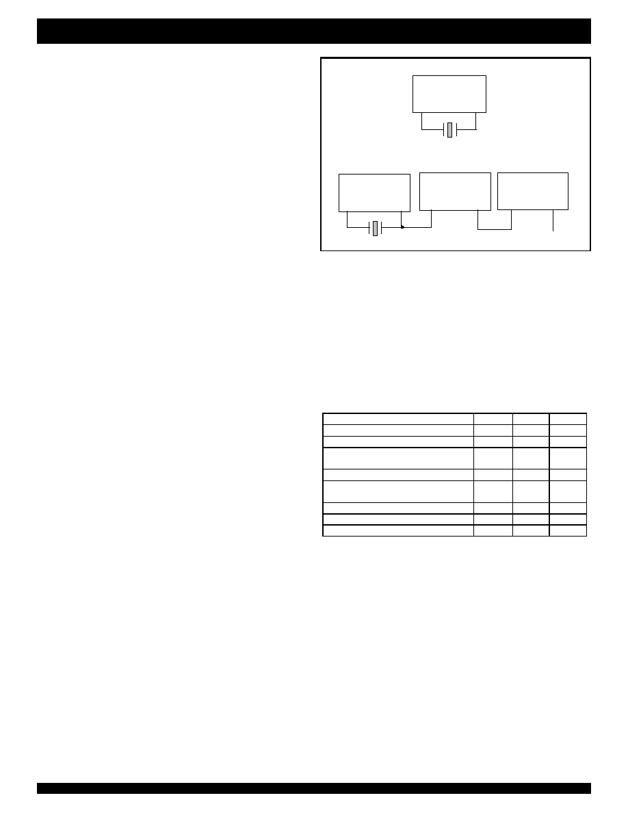
Crystal Oscillator
A 3.579545 MHz crystal oscillator or other external clock source is
required for NW6005. The crystal can be directly connected between
OSCIN and OSCOUT pins without any external component. If an
external clock source is used, OSCIN pin should be driven by the
clock source and OSCOUT pin is left floating or is used to drive other
devices. Fig. 8 shows some applications.
FSK CARRIER DETECTION
The carrier detector detects the presence of a signal of sufficient
amplitude at the output of the FSK bandpass filter. If the signal is
qualified by a digital algorithm, it set the CD output to low indicating a
successful carrier detection. NW6006 supplies a 10 ms hysteresis to
allow for momentary signal drop out once CD has been activated.
When there is no activity at the FSK bandpass filter output for 10 ms,
CD is released.
When CD is inactive (high), the raw output of the FSK
demodulator is ignored by the FSK data output interface. In mode`0',
the DATA pin is forced high. In mode `1', the internal shift register is not
updated. If DCLK is clocked, DATA is undefined.
Since signals such as DT-AS, DTMF tones and speech are within
the FSK frequency band and thus may activate the carrier detector.
The NW6006 should be put into DT-AS or power down mode when
FSK is not expected to avoid false carrier detection and false
demodulation.
to the next device
(b) Common Crystal Connection of Several Devices
Sharing One Timing Source
(a) Connection of One Device with Crystal Oscillator
NW6006
OSCIN
OSCOUT
3.579545MHz
NW6006
OSCIN
OSCOUT
NW6006
OSCIN
OSCOUT
NW6006
OSCIN
OSCOUT
3.579545MHz
Figure 8. Applicaiton of Clock Driven Circuit
APPLICATION NOTE
CONTROL BITS PROGRAMMING
Functionality of the NW6006 can be selected by coding CB0-CB2,
as shown in Table 2.
Table 2. Control Bits Programming
Functionality Group
CB0
CB1
CB2
FSK Demodulation Mode 0
0
1
1
FSK Demodulation Mode 1
1
1
1
Hybrid DT-AS Detection with Stuttered
Dial Tone Detection
1
1
0
Hybrid DT-AS Detection Only
0
1
0
Tip/Ring DT-AS Detection with Stuttered
Dial Tone Detection
1
0
1
Tip/Ring DT-AS Detection Only
0
0
1
Power Down
1
0
0
Factory Test Only
0
0
0
HYBRID CONNECTION
To optimize the device's talkdown and talkoff performance, Hybrid
connection is recommended. There are two Op Amps in NW6006
which bring convenience for Hybrid connection. When connected to
the Hybrid Op Amp, the Hybrid circuit will attenuate the speech signal
at least 9 dB from the microphone to the speaker, which leads a much
better performance of near-end talkdown and talkoff.
It is highly recommended to demodulate the FSK signal using the
Tip/Ring OP Amp and to detect the CAS signal using the Hybrid OP
Amp. This implementation brings not only optimized talkdown and
talkoff performance, but also the convenience to adjust FSK and CAS
sensitivity separately.

9
INDUSTRIAL TEMPERATURE RANGE
NW6006 ENHANCED TYPE II CALLER ID DECODER
WITH STUTTER DIAL TONE DETECTOR
GAIN SETTING
Ideally, the gain of the two Op Amps would be set to 0 dB. But in
real applications, the gain setting should be determined by industry
standards as well as by customer requirements. The circuit and
calculation method of gain setting is illustrated in Figs. 3 and 4. For
Hybrid connection, the single-ended solution (Fig. 4) is often selected.
Typically, the CAS sensitivity should be lower than the FSK
sensitivity in order to prevent missing the FSK signal while the CAS
signal is detected. Therefore, it is suggested to set the gain of the Op
Amp for FSK demodulation 3 dB higher than that of the Op Amp for
CAS detection.
THE DIFFERENCE BETWEEN FSK MODE 0 AND MODE1
In FSK mode 0, the FSK serial bit stream is output to the DATA pin
directly. DCLK and DR pins are unused. The microcontroller reads out
the data by the serial data interface which is implemented by software
programming. The flexibility of using software improves the immunity
to interference.
In FSK mode 1, the received byte is stored in an on-chip register.
The microcontroller supplies read pulses (DCLK) to shift the register
contents serially out of the NW6006, onto the DATA pin. The DR pin is
also used to indicate the word boundary.
VALID DT-AS EVALUATION
DT-AS output will generate false detection if being interfered by
speech. In this way, valid DT-AS pulse evaluation becomes necessary.
The evaluation defines a minimum and maximum pulse duration,
and maximum drop out time within that pulse duration. See Figure 22
for reference.
10
INDUSTRIAL TEMPERATURE RANGE
NW6006 ENHANCED TYPE II CALLER ID DECODER
WITH STUTTER DIAL TONE DETECTOR
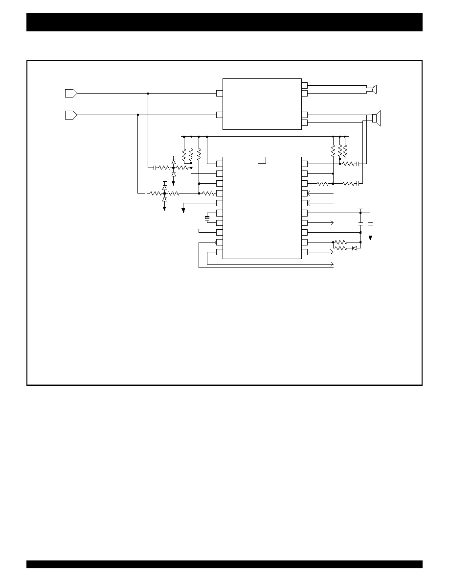
APPLICATION INFORMATION
Figure 9. Typical Application Circuit For Bellcore MEI Compatible Type II Telephone
with Stutter Dial Tone Detection, 5 V Operation
NW6006
VREF
IN1+
IN1-
GS1
GND
OSCIN
OSCOUT
CB0
DCLK
DATA
IN2+
IN2-
GS2
CB2
CB1
VCC
CD
/
STRDT
ST/GT
EST
DR
/
STD
Telephone
Hybrid
TIP
RING
Tx+
Tx-
Rx-
Rx+
Speaker
R1
R2
TIP
RING
C1
C2
39k
39k
470k
56k
56k
GND
470k
470k
2n2
2n2
56k
56k
330k
R3
R4
100n
100n, 20%
VCC= 5V +/-10%
FSK Interface Mode 1 is selected
Xtal
To Microcontroller
From Microcontroller
470k
470k
Microphone
Note:
1. Resistors are 1%, 0.1Watt; Unless stated, capacitors are 5%, 6.3 V.
2. All diodes in the circuit are 1N4148 or equivalent.
3. Xtal is 3.579545 MHz, 0.1% crystal or ceramic resonator.
4. Tip/Ring op amp gain = 0 dB; Hybrid Receive op amp gain = -3 dB.
5. For 1000 Vrms, 60 Hz isolation from Tip to Earth and Ring to Earth:
R1, R2 = 430 k, 0.5 W, 5%, 500 V min. C1, C2 = 2n2, 250 V min.
6. For BT application, R3=R4= 422k;
For Bellcore application, R3=825k, R4=226k.
A
B
11
INDUSTRIAL TEMPERATURE RANGE
NW6006 ENHANCED TYPE II CALLER ID DECODER
WITH STUTTER DIAL TONE DETECTOR
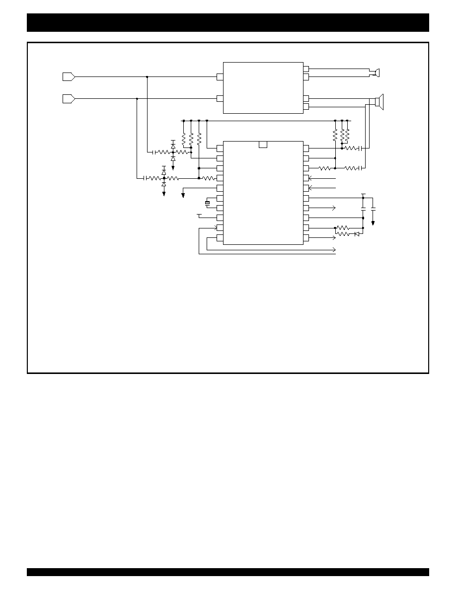
Figure 10. Typical Application Circuit For Bellcore MEI Compatible Type II Telephone
with Stutter Dial Tone Detection, 3 V Operation
NW6006
VREF
IN1+
IN1-
GS1
GND
OSCIN
OSCOUT
CB0
DCLK
DATA
IN2+
IN2-
GS2
CB2
CB1
VCC
CD/STRDT
ST/GT
EST
DR/STD
Telephone
Hybrid
TIP
RING
Tx+
Tx-
Rx-
Rx+
Speaker
R1
R2
TIP
RING
C1
C2
39k
39k
282k
56k
56k
GND
470k
470k
2n2
2n2
56k
56k
200k
R3
R4
100n
100n, 20%
VCC= 3V +/-10%
FSK Interface Mode 1 is selected
Xtal
To Microcontroller
From Microcontroller
282k
282k
Microphone
Note:
1. Resistors are 1%, 0.1Watt; Unless stated, capacitors are 5%, 6.3 V.
2. All diodes in the circuit are 1N4148 or equivalent.
3. Xtal is 3.579545 MHz, 0.1% crystal or ceramic resonator.
4. Tip/Ring op amp gain = 0 dB; Hybrid Receive op amp gain = -3 dB.
5. For 1000 Vrms, 60 Hz isolation from Tip to Earth and Ring to Earth:
R1, R2 = 430 k, 0.5 W, 5%, 500 V min. C1, C2 = 2n2, 250 V min.
6. For BT application, R3=R4= 422k;
For Bellcore application, R3=825k, R4=226k.
A
B

12
INDUSTRIAL TEMPERATURE RANGE
NW6006 ENHANCED TYPE II CALLER ID DECODER
WITH STUTTER DIAL TONE DETECTOR
..101010..
Data
...
...
PWDN
FSKEN
CD
DR
DCLK
DATA
Ch. Seizure
Mark
Message
A
B
C
D
E
F
Alerting Signal
A/B Wires
1st Ringing
2nd Ringing
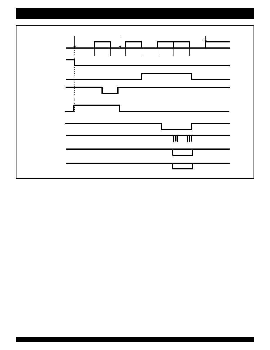
Figure 11. Bellcore On-hook Data Transmission Timing Diagram
Notes:
1) A= 2 sec typ., B= 250 - 500 ms, C= 250 ms, D= 150ms, E depends on data length, Max C+D+E = 2.9 - 3.7 sec, F
200 ms.
2) In a battery operated CPE, NW6006 may be enabled only after the end of ringing to conserve power.
3) The microcontroller in the CPE powers down the NW6006 after CD goes inactive.
4) The microcontroller times out if CD is not activated on the 2nd ring and puts the device into Power-down mode.
5) FSK may be always enabled while the CPE is on-hook. To prevent the FSK demodulator from reacting to other inband signals such as speech, DT-AS or DTMT tones. The designer may
choose to disable FSKduring the period that FSK signal is not expected.
6) PWDN and FSKEN are internal signals decoded from Control Bits CB2-0.
7) When CB0 is low, both DR and DCLK pins are unused.
Note 2
Note 1
Note 2
Note 3
Note 4
Note 5
Note6
Note6
Note 7
Note 7
13
INDUSTRIAL TEMPERATURE RANGE
NW6006 ENHANCED TYPE II CALLER ID DECODER
WITH STUTTER DIAL TONE DETECTOR
CAS
Mark
Message
CPE off-hook
CPE mutes handset and
disable keypad
CPE unmutes handset and
enable keypad
A
B
C
D
E
F
G
A/B wires
PWDN
FSKEN
CPE sends
ACK
STD
...
Data
CD
DR
DCLK
DATA
Hybrid
DT-ASEN
Notes:
1) A= 75 - 85 ms, B= 0 -100 ms, C= 55 - 65 ms, D= 0 - 500 ms, E= 58 - 75ms, F depends on data length, G
50 ms.
2) If AC power is not available, the designer may use the line power when the CPE goes off-hook and use battery power while on-hook. The CPE should also be CID (on-hook) capable .
3) If the end office fails to send the FSK signal, the CPE should disable FSKEN and unmute the handset and enable the keypad after this interval.
4) When FSK signal is not expected, the FSKEN should be set low to disable the FSK demodulator.
5) FSKEN should be high as soon as the CPE has finished sending the acknowledgement signal ACK.
6) FSKEN should be low when CD become inactive.
7) PWDN, FSKEN and Hybrid DT-ASEN are internal signals decoded from Control Bits CB2-0.
8) When CB0 is low, both DR and DCLK pins are unused.
Note 1
Note 2
Note 3
Note 4
Note 5
Note 6
Figure 12. Bellcore Off-hook Data Transmission Timing Diagram
Note7
Note7
Note7
Note8
Note8

14
INDUSTRIAL TEMPERATURE RANGE
NW6006 ENHANCED TYPE II CALLER ID DECODER
WITH STUTTER DIAL TONE DETECTOR
Alerting
Signal
Ch. Seizure
Mark
Message
Ring
..101010..
Data
...
...
A
B
C
D
E
F
G
Line Reversal
A/B Wires
PWDN
STD
TE DC load
TE AC load
FSKEN
CD
DR
DCLK
DATA
15 ±1 ms
20 ±5 ms
<120
µ
A
50 - 150 ms
< 0.5 mA (optional)
Current Wetting Pulse
Zss
Tip/Ring
DT-ASEN
Note 1
Note 2
Note 3
Note 4
Notes:
1) A
100ms, B=88 - 110 ms, C
45 ms (up to 5 sec), D= 80 -262 ms, E= 45 - 75 ms, F
2.5 sec (typ. 500 ms), G
200 ms.
2) By choosing t
GA
=15 ms, t
ABS
will be 15-25 ms (refer to Fig. 8). Current wetting pulse and AC/DC load should be applied right after the STD rising edge.
3) AC and DC loads should be removed between 50-150 ms after the end of the FSK signal. The NW6006 may go to power down mode to save power.
4) FSKEN should be set low to disable the FSK demodulator, when the FSK signal is not expected.
5) Tip/Ring DT-ASEN, PWDN and FSKEN are internal signals decoded from Control Bits CB2-0.
6) When CB0 is low, both DR and DCLK pins are unused.
Figure 13. BT Idle State (on-hook) Data Transmission Timing Diagram
Note 5
Note 5
Note 5
Note 6
Note 6

15
INDUSTRIAL TEMPERATURE RANGE
NW6006 ENHANCED TYPE II CALLER ID DECODER
WITH STUTTER DIAL TONE DETECTOR
MAXIMUM RATING
- Exceeding the following listed values may cause permanent damage.
Power Supply Voltage: -0.3 V to 6 V
Voltage on any pin other than supplies: GND - 0.3 V to VCC + 0.3 V
Current at any pin other than supplies:
10 mA
Storage Temperature: -65 ∞C to +150 ∞C
RECOMMENDED OPERATING CONDITIONS
Operating Temperature: -40 ∞C to +85 ∞C
Power Supply Voltage: 3 V ± 10% or 5 V ± 10%
Clock Frequency: 3.579545 MHz ± 0.1%
Input Voltage: 0 V to VCC
CRYSTAL SPECIFICATIONS
Frequency: 3.579545 MHz
Resonancy tolerance: ± 0.1%( -40∞C to +85∞C)
Resonance mode: Parallel
Load capacitance: 18 pF
Maximum series resistance: 150
Maximum drive level: 2 mW
DC ELECTRICAL CHARACTERISTICS
Test 1: All inputs are VCC/GND except for oscillator pins. No analog input. Output unloaded. NW6006 in power down mode.
Test 2: All inputs are VCC/GND except for oscillator pins. No analog input. Ouput unloaded. FSK is enabled.
Parameter
Pin
Description
Min
Typ
Max
Units
Test Conditions
I
CCS
Power Supply Standby
Current
0.5
15
µ
A
Test 1
I
CC
VCC
Operating Supply Current
VCC = 5 V
±
10%
VCC = 3 V
±
10%
2.5
1.8
3.8
2.7
mA
mA
Test 2
V
T+
Schmitt Trigger Input High
Threshold
0.5VCC
0.7VCC
V
V
T-
DCLK
Schmitt Trigger Input Low
Threshold
0.3VCC
0.5VCC
V
V
HYS
Schmitt Hysteresis
0.2
V
V
IH
CB0
CB1
CMOS Input High Voltage
0.7VCC
VCC
V
V
IL
CB2
CMOS Input Low Voltage
GND
0.3VCC
V
I
OH
DCLK, DATA, EST
DR/STD, CD, ST/GT
Output High Sourcing
Current
-0.8
mA
V
OH
=0.9VCC
16
INDUSTRIAL TEMPERATURE RANGE
NW6006 ENHANCED TYPE II CALLER ID DECODER
WITH STUTTER DIAL TONE DETECTOR
Parameter
Pin
Description
Min
Typ
Max
Units
Test Conditions
I
OL
DCLK, DATA
DR/STD, CD
EST, ST/GT
Output Low Sinking
Current
2
mA
V
OL
= 0.1VCC
Iin1
IN1+, IN1-
IN2+, IN2-
Input Current
1
µ
A
Iin2
DCLK
CB0, CB1, CB2
Input Current
10
µ
A
V
in
= VCC to GND
I
OZ
1
ST/GT
Output High Impedance
5
µ
A
V
out
= VCC to GND
VREF
Output Voltage
0.5VCC-0.1
0.5VCC+0.1
V
No Load
RREF
VREF
Output Resistance
2
k
V
TGT
ST/GT
Comparator Threshold
Voltage
0.5VCC-0.05
0.5VCC+0.05
V
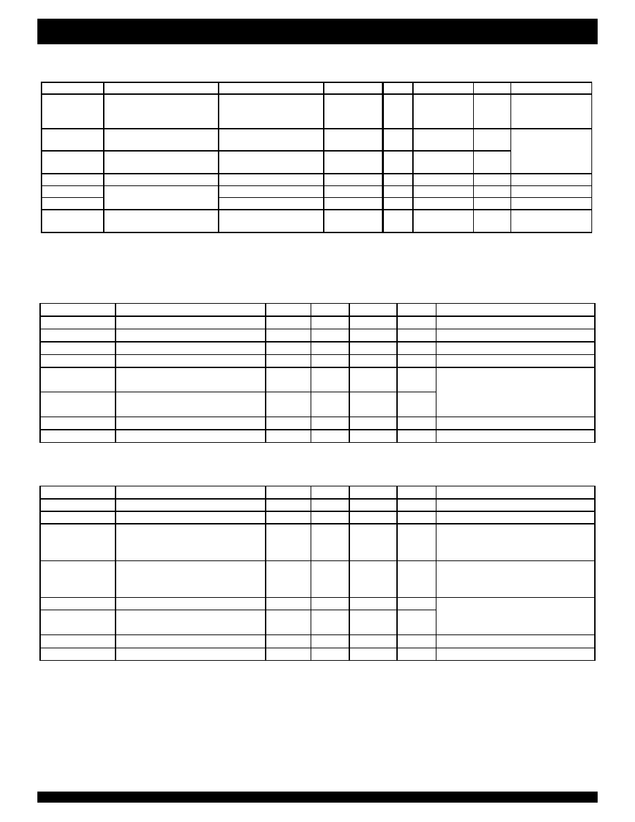
DC ELECTRICAL CHARACTERISTICS (CONTINUED)
Parameter
Description
Min
Typ
Max
Units
Notes
F
L
Low Tone Frequency
2130
Hz
Nominal frequency
F
H
High Tone Frequency
2750
Hz
Nominal frequency
FDA
Frequency Deviation Accept
1.1%
Within this range, tones are accepted.
FDR
Frequency Deviation Reject
3.5%
Outside this range, tones are rejected.
SIGAC
Accept Signal Level per tone
-40
-2
dBV
SIGRJ
Reject Signal Level per tone
(VCC = 5 V
±
10%, 3 V
±
10%)
-47
dBV
Input op amp configured to 0 dB gain for
5 V operation, gain for 3 V operation is
TBD. Signal level is per tone.
TA
Positive and Negative Twist Accept #
7
dB
SNR
Signal to Noise Ratio ##
20
dB
AC ELECTRICAL CHARACTERISTICS
DUAL TONE ALERT SIGNAL DETECTION
# Twist = 20 |log ( f
H
amplitude / f
L
amplitude )|.
## Both tones have the same amplitude and at nominal frequencies. Band limited random noise 300-3400 Hz. Measurement valid only when tone is present.
Parameter
Description
Min
Typ
Max
Units
Notes
F
L
Low Tone Frequency
350
Hz
Nominal frequency
F
H
High Tone Frequency
440
Hz
Nominal frequency
FDA
Frequency Deviation Accept
High Tone
Low Tone
-7
-9
7
9
Hz
Within this range, tones are accepted.
FDR
Frequency Deviation Reject
High Tone
Low Tone
-13
-11
13
11
Outside this range, tones are rejected.
SIGAC
Accept Signal Level per tone
-31
-12
dBV
SIGRJ
Reject Signal Level per tone
(VCC = 5 V
±
10%, 3 V
±
10%)
-36
dBV
Input op amp configured to 0 dB gain for
5 V operation, gain for 3 V operation is
TBD. Signal level is per tone.
TA
Positive and Negative Twist Accept #
-6
6
dB
SNR
Signal to Noise Ratio ##
20
dB
STUTTER DIAL TONE SIGNAL DETECTION

17
INDUSTRIAL TEMPERATURE RANGE
NW6006 ENHANCED TYPE II CALLER ID DECODER
WITH STUTTER DIAL TONE DETECTOR
AC ELECTRICAL CHARACTERISTICS (CONTINUED)
GAIN ADJUSTABLE OP AMP
Parameter
Description
Min
Typ
Max
Units
Test Conditions
I
IN
Input Leakage Current
1
µ
A
GND
V
IN
VCC
R
IN
Input Resistance
10
M
V
OS
Input Offset Voltage
10
mV
PSRR
Power Supply Rejection Ratio
40
dB
1kHz ripple on VCC
CMRR
Common Mode Rejection
30
dB
V
CMmin
V
IN
V
CMmax
A
VOL
DC Open Loop Voltage Gain
50
dB
f
C
Unity Gain Bandwidth
0.3
MHz
V
O
Output Voltage Swing
0.5
VCC -0.5
V
Load
100 k
C
L
Maximum Capacitive Load (GS)
50
pF
R
L
Maximum Resistive Load (GS)
100
k
V
CM
Common Mode Range Voltage
1.0
VCC-1.0
FSK DETECTION
Parameter
Description
Min
Typ
Max
Units
Notes
ID
Input Detection Level
-40
-6.5
dBV
RS
Reject Signal Level
-48
dBV
Production tested at VCC =3V
±
10%, or 5V
±
10%. Both mark and space have the same
amplitude.
TR
Transmission Rate
1188
1200
1212
baud
FMARK
Input Frequency Detection
Bell 202 `1' (mark)
1188
1200
1212
Hz
FSPACE
Input Frequency Detection
Bell 202 `0' (space)
2178
2200
2222
Hz
FMARK
Input Frequency Detection
ITU-T V.23 `1' (mark)
1280.5
1300
1319.5
Hz
FSPACE
Input Frequency Detection
ITU-T V.23 0 (space)
2068.5
2100
2131.5
Hz
TA
Positive and Negative Twist Accept
-10
10
dB
SNR
Signal to Noise Ratio
20
dB
Both mark and space have the same amplitude
and at nominal frequencies. Band limited
random noise: 200-3400 Hz. Present only when
FSK signal is present. #
# BT band is 200-3400 Hz, while Bellcore band is 0-4 kHz.
Notes:
dBV = decibels above or below a reference voltage of 1 Vrms.

18
INDUSTRIAL TEMPERATURE RANGE
NW6006 ENHANCED TYPE II CALLER ID DECODER
WITH STUTTER DIAL TONE DETECTOR
AC TIMING CHARACTERISTICS
POWER UP/DOWN AND FSK DETECTION
Parameter
Description
Min
Typ
Max
Units
Test Conditions
t1
Power Up Time
50
ms
t2
Power Down Time
1
ms
t3
Input FSK to CD low delay
25
ms
t4
Input FSK to CD high delay
10
ms
t5
Hysteresis
10
ms
DUAL TONE ALERT SIGNAL
Parameter
Description
Min
Typ
Max
Units
Test Conditions
t6
Alert Signal Present Detect Time
4
14
ms
t7
Alert Signal Absent Detect Time
0.1
8
ms
Power down is
enabled by
Control Bits
OSCOUT
t1
t2
Figure 14. Power Up/Down Timing
Figure 15. FSK Detection Time
Tip/Ring
CD
FSK Signal
t3
t4
Tip/Ring
or Hybrid
Receive Pair
EST
Alert Signal
t6
t7
Figure 16. Dual Tone Alert Signal Detection Time
19
INDUSTRIAL TEMPERATURE RANGE
NW6006 ENHANCED TYPE II CALLER ID DECODER
WITH STUTTER DIAL TONE DETECTOR
Parameter
Description
Min
Typ
Max
Units
Test Conditions
t11
DCLK Cycle Time
1
µ
s
t12
DCLK High Time
0.3
µ
s
t13
DCLK Low Time
0.3
µ
s
t14
DCLK Rise Time
100
ns
t15
DCLK Fall Time
100
ns
t16
DCLK Low Setup to DR
500
ns
t17
DCLK Low Hold Time after DR
500
ns
AC TIMING CHARACTERISTICS (CONTINUED)
SERIAL INTERFACE (MODE `1')
DCLK
t13
t14
t12
t15
t11
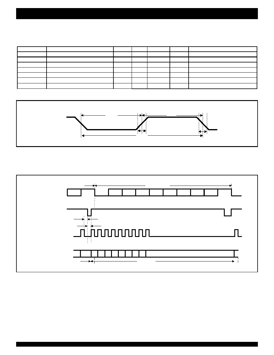
Figure 17. DCLK Timing in Mode `1'
Figure 18. Serial Data Interface Timing in MODE `1'
Notes:
1. DCLK clears DR.
2. DR not cleared by DCLK, low for a maximum time of 1/2 bit width.
b7
b0
b1
b2
b3
b4
b5
b6
b7
b7
stop b0 b1
stop
start
stop
b0
Nth byte
(N-1)th byte
Nth byte
(N+1)th byte
t16
t17
Internal
Demodulated Bit
Stream
DR
DCLK
DATA
note 1
note 2
start
b2 b3 b4 b5 b6 b7
stop

20
INDUSTRIAL TEMPERATURE RANGE
NW6006 ENHANCED TYPE II CALLER ID DECODER
WITH STUTTER DIAL TONE DETECTOR
AC TIMING CHARACTERISTICS (CONTINUED)
b7
1
0
b0 b1 b2 b3 b4 b5 b6 b7 1
0
b0 b1 b2 b3 b4 b5 b6 b7 1
0
b0 b1
b0 b1 b2 b3 b4 b5 b6 b7
b0 b1 b2 b3 b4 b5 b6 b7
b0 b1 b2
b7
TIP/RING
DATA
stop
stop
stop
stop
start
start
start
start
start
start
t21
Nth byte
(N+1)th byte
Nth byte
(N+1)th byte
Figure 20. Serial Data Interface Timing in MODE `0'
Parameter
Description
Min
Typ
Max
Units
Test Conditions
D
R
Data Rate
1188
1200
1212
baud
1
t21
Input FSK to DATA Delay
1
5
ms
t22
DATA Rise Time
200
ns
2
t23
DATA Fall Time
200
ns
2
SERIAL INTERFACE (MODE `0')
Test conditions:
1. FSK input data at 1200 ±
12 buad.
2. Load of 50 pF.
DATA
t23
t22
Figure 19. DATA Output Timing in Mode `0'

21
INDUSTRIAL TEMPERATURE RANGE
NW6006 ENHANCED TYPE II CALLER ID DECODER
WITH STUTTER DIAL TONE DETECTOR
STUTTER DIAL TONE SIGNAL
Parameter
Description
Min
Typ
Max
Units
Test Conditions
t18
Stutter Dial Tone Signal Present Detect
Time
40
50
68
ms
t19
Stutter Dial Tone Signal Absent Detect
Time
32
48
52
ms
t20
Stutter Dial Tone Signal Duration Time
64
100
108
ms
SDT signal 100 ms on, 100 ms off.
Figure 21. Stutter Dial Tone Signal Detection Time
Tip/Ring
or Hybrid
Receive Pair
STRDT
t18
t19
Dial Tone
Signal
t20
Maximum Dropout
Span
Pulse Duration
Min.
Min
Max.
Figure 22. Valid DT-AS Pulses
22
CORPORATE HEADQUARTERS
for SALES:
for Tech Support:
2975 Stender Way
800-345-7015 or 408-727-6116
408-330-1552
Santa Clara, CA 95054
fax: 408-492-8674
email: telecomhelp@idt.com
www.idt.com
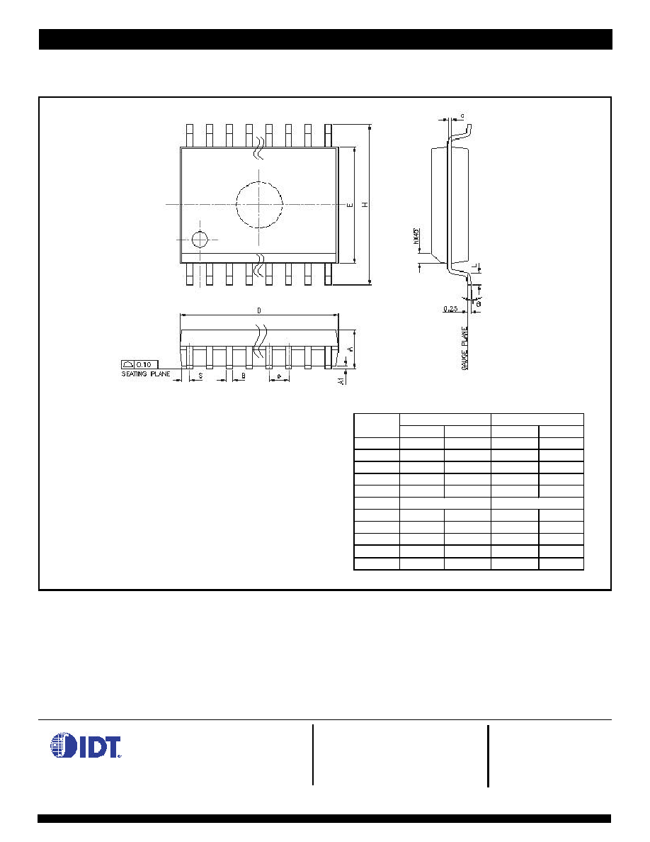
Figure 23. NW6006-XS 20 Pin SOIC Package Diagram
PHYSICAL DIMENSIONS
in Millimeters
Dimension in MM
Dimension in Inch
Symbol
Min
Max
Min
Max
A
2.35
2.65
0.093
0.104
A1
0.10
0.30
0.004
0.012
B
0.33
0.51
0.013
0.020
C
0.23
0.32
0.009
0.013
E
7.40
7.60
0.291
0.299
e
1.27 BSC
0.050 BSC
H
10.00
10.65
0.394
0.419
h
0.25
0.75
0.010
0.029
L
0.40
1.27
0.016
0.050
0
8
0
8
D
12.60
13.00
-
-