
Fiber Optics
NOVEMBER 1999
5 V
V23806-S84-Z3
3.3 V
V23806-S84-Z4
Testboard for ATM, ESCON, Fibre Channel and
Gigabit Ethernet 1x9 Transceivers
FEATURES
∑ Allows for separate powering of receiver and transmitter sec-
tion
∑ Power supply lines filtered externally to module under test
∑ Signal Detect level displayed by LED
∑ Power supply can be interrupted separately for receiver and
transmitter
∑ External Data and Signal Detect interfaces are made through
high performance SMA connectors
∑ Receiver data outputs are DC coupled. Output voltage can be
directly measured at SMA connectors
DESCRIPTION
This testboard is a functional test fixture intended for use with
the 1x9 pin row single mode 155MBd or 622MBd ATM trans-
ceiver, ESCON, Fibre Channel and Gigabit Ethernet transceiv-
ers. It provides a test medium for characterizing the
performance of these transceivers.
Figure 1. Application board (Top view)
SMA-connector (female)
Power supply connector
(female)
LED (red)
3-Pin jumper, to measure
and to interrupt receiver/
transmitter power supply
RxSD
RxVCC
RxD
RxD
TxD
TxD
GND
TxVCC
Infineon
Fiber Optics
V23806-S84-Z3/Z4
APPLICATION BOARD ATM/ESCON/FC/GBd Ethernet
155-1250 MBd
3.3 V/5 V - Version

Fiber Optics
V23806-S84-Z3/Z4, Testboard for ATM, ESCON, Fibre Channel, GBE 1x9 Trx
2
Connectors/Test Pins
Notes
1. Some transceiver versions have TTL-SD-output. For this type no load is required.
Indicators/Switches
Label
Type
Name
Level
Description
SD
(1)
SMA
Signal Detect Output
PECL Output
To measure use 50
load to V
EE
RxD
SMA
Receiver Data Output
PECL Output
Load is 50
to V
EE
(GND), DC coupled
or
AC coupled, depending on board assembly
(see page 4)
RxDn
SMA
Receiver Data Not Output
PECL Output
TxD
SMA
Transmitter Data Input
PECL Input
Load is 50
to V
EE
(GND), AC coupled
(see page 4)
TxDn
SMA
Transmitter Data Not Input
PECL Input
V
CC
Power Supply
In accordance with recommended operating conditions of transceiver
(3.3V / 5V)
V
EE
Ground
Label
Type
Name
Level
Description
SD
LED
Signal Detect Indicator
active high
LED off: SD off
LED on: SD on
JMP
Jumper
Signal Detect
connects signal detect to either SMA
connector or OPAMP (LED)
Fiber Optics
V23806-S84-Z3/Z4, Testboard for ATM, ESCON, Fibre Channel, GBE 1x9 Trx
3
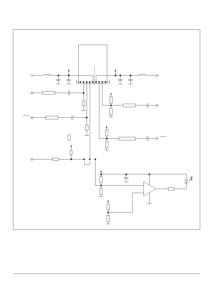
Figure 2. Schematic of Application board (initial assembly)*
* Suitable for DC/DC Transceiver only. For AC/AC and AC/DC please see page 4.
** Remove when TTL-SD; change resistor to value in double brackets.
FO-Transceiver
Top view
Rx
Tx
RxV
CC
TxV
CC
RxV
CC
TxV
CC
RxD
RxD
SD
TxD
TxD
100 nF
50
stripline
300
(150
)
100 nF
50
stripline
300
(150
)
RxV
CC
82
**
(127
)
75
(33
)
**
Jumper SD
RxV
CC
82
**
(127
)
127
**
(82
)
1.5 K
4.3 K
(2.2 K)
((1.0 K))**
-
+
LM 319
150
191
(127
)
68
(82
)
191
(127
)
68
(82
)
100 nF
50
stripline
100 nF
50
stripline
TxV
CC
TxV
CC
Values in brackets: 3.3 V board
R3
R4
R9
R7
C11
C12
R10
R8
1
C2
C1

Fiber Optics
V23806-S84-Z3/Z4, Testboard for ATM, ESCON, Fibre Channel, GBE 1x9 Trx
4
Variation of Testboard for different type of electrical trans-
ceiver interfaces.
Values in brackets refer to 3.3 V operation. Part numbers of pas-
sive components refer to Fig. 9 to 12 (Assembly plan).
Figure 3. DC-type receiver (V23826-XXX-C(3)6X, V23806-
A84-XXX, V23809-E11-C10) - AC-coupled to test (initial as-
sembly)
Figure 4. DC type receiver (V23826-XXX-C(3)6X, V23806-
A84-XXX, V23809-E11-C10) - DC-coupled to test system
Figure 5. AC-type receiver V23826-XXX-C(3)53
Figure 6. DC-type transmitter (V23826-XXX-C(3)6X, V23806-
A84-XXX, V23809-E11-C10) -AC-coupled to test (initial as-
sembly)
(1)
Figure 7. DC-transmitter (V23826-XXX-C(3)6X, V23806-A84-
XXX, V23809-E11-C10) - DC-coupled to test
(1)
Figure 8. AC-type transmitter V23826-XXX-C(3)13, V23826-
XXX-C(3)53
(1)
Assembly Plan
Figure 9. Top side (Detail of Figure 11)
Figure 10. Bottom side (Detail of Figure 12)
Note:
1. It is recommended to drive the transmitter with differential signals.
50 Ohm Stripline
Rx-Out
C1/2
R3/4
50 Ohm
R3/4 = 300 (150) Ohm
C1/2 = 100 nF in position of R1/2
Rx-Out
V
CC
R5/6
R1/2
50 Ohm Stripline
50 Ohm
R5/6 = 82 (127) Ohm
R1/2 = 75 (33) Ohm
Output Voltage divided by 2.5 (1.66)
50 Ohm Stripline
Rx-Out
50 Ohm
R3/4 = removed
R5/6 = removed
C1/2 = shorted
Tx-In
Puls
Gen.
50 Ohm Stripline
R9/10
C11/12
R7/8
V
CC
R9/10 = 68 (82) Ohm
R7/8 = 191 (127) Ohm
C11/12 = close to SMA-
connector (100 nF)
Tx-In
Puls
Gen.*
50 Ohm Stripline
R9/10
R7/8
V
CC
R9/10 = 68 (82) Ohm
R7/8 = 191 (127) Ohm
C11/12 = shorted
*) PECL
Driver
Tx-In
50 Ohm Stripline
R9/10 = removed
R7/8 = removed
C11/12 = shorted
Puls
Gen.
PIN 1
Rx-Part
Tx-Part
R/C2
R/C1
10 nF
10 nF
R1
0
R9
R8
R7
R3
R5
R6
R4
PIN 1
Rx-Part
Tx-Part
C
VC
C
C
VC
C

Published by Infineon Technologies AG
©
Infineon Technologies AG 1999
All Rights Reserved
Attention please!
The information herein is given to describe certain components and shall not be
considered as warranted characteristics.
Terms of delivery and rights to technical change reserved.
We hereby disclaim any and all warranties, including but not limited to warranties
of non-infringement, regarding circuits, descriptions and charts stated herein.
Infineon Technologies is an approved CECC manufacturer.
Information
For further information on technology, delivery terms and conditions and prices
please contact the Infineon Technologies offices or our Infineon Technologies
Representatives worldwide - see our webpage at
www.infineon.com/fiberoptics
Warnings
Due to technical requirements components may contain dangerous substances.
For information on the types in question please contact your Infineon Technologies
offices.
Infineon Technologies Components may only be used in life-support devices or
systems with the express written approval of Infineon Technologies, if a failure of
such components can reasonably be expected to cause the failure of that
life-support device or system, or to affect the safety or effectiveness of that device
or system. Life support devices or systems are intended to be implanted in the
human body, or to support and/or maintain and sustain and/or protect human life.
If they fail, it is reasonable to assume that the health of the user or other persons
may be endangered.
Infineon Technologies AG ∑ Fiber Optics ∑ Wernerwerkdamm 16 ∑ Berlin D-13623, Germany
Infineon Technologies, Corp. ∑ Fiber Optics ∑ 19000 Homestead Road ∑ Cupertino, CA 95014 USA
Infineon Technologies K.K. ∑ Fiber Optics ∑ Takanawa Park Tower ∑ 20-14, Higashi-Gotanda, 3-chome, Shinagawa-ku ∑ Tokyo 141, Japan
Figure 11. Top side of application board
Figure 12. Bottom side of application board
PIN 1
C11/12
PIN 1