Data Sheet
1
2001-10-01
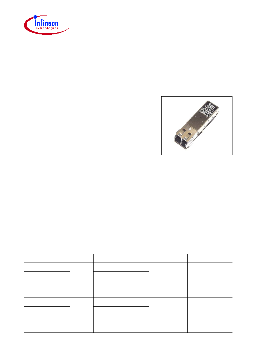
Small Form Factor
Single Mode 1300 nm 622 MBd Transceiver
2x5/2x10 Pinning with LCTM Connector, with Collar
V23818-H18-Lx
Preliminary Data
Part Number
Pinning Temperature Range Signal Detect Input
Output
V23818-H18-L37
2x5
0įC to 70įC
PECL
DC
DC
V23818-H18-L36
-40įC to 85įC
V23818-H18-L47
0įC to 70įC
TTL
AC
AC
V23818-H18-L46
-40įC to 85įC
V23818-H18-L17
2x10
0įC to 70įC
PECL
DC
DC
V23818-H18-L16
-40įC to 85įC
V23818-H18-L57
0įC to 70įC
TTL
AC
AC
V23818-H18-L56
-40įC to 85įC
LCTM is a trademark of Lucent
Fiber Optics
Features
∑ Small Form Factor transceiver
∑ RJ-45 style LC connector system
∑ Half the size of SC Duplex 1x9 transceiver
∑ Single power supply (+3.3 V)
∑ Extremely low power consumption
∑ Loss of optical signal indicator
∑ Laser disable input
∑ PECL differential inputs and outputs
∑ Distance up to 15 km on Single Mode Fiber
∑ Class 1 FDA and IEC laser safety compliant
∑ Multisource footprint
∑ Small footprint for high channel density
∑ UL 94 V-0 certified
∑ Compliant with FCC (Class B) and EN 55022
∑ Tx and Rx power monitor
V23818-H18-Lx
Pin Configuration
Data Sheet
2
2001-10-01
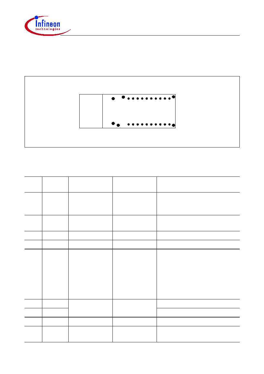
Pin Configuration
2x10 Transceiver
Figure 1
20 Pin Module
Pin Description
Pin
No.
Symbol
Level/Logic
Function
Description
1
RxPMon Analog Current
Rx Power
Monitor
Do not connect if not used (see
"Application Notes" on
Page 13
).
2, 3, 6 Rx
V
EE
Power Supply
Rx Ground
Negative power supply,
normally ground
4, 5
NC
Pin not connected
7
Rx
V
CC
Power Supply
Rx + 3.3 V
Positive power supply, +3.3 V
8
SD
PECL/TTL Out-
put active high
Rx Signal
Detect
A high level on this output shows
that optical data is applied to the
optical input.
PECL Output active high for
V23818-H18-L16/L17
TTL Output active high for
V23818-H18-L56/L57
9
RxDn
PECL Output
Rx Output Data
Inverted receiver output data
10
RxD
Receiver output data
11
Tx
V
CC
Power Supply
Tx + 3.3 V
Positive power supply, +3.3 V
12, 16 Tx
V
EE
Power Supply
Tx Ground
Negative power supply,
normally ground
Tx
Rx
20
HL4
HL1
HL2
HL3
19 18 17 16 15 14 13 12 11
1 2 3 4 5 6 7 8 9 10
20-PIN MODULE - TOP VIEW
MS2
MS1
V23818-H18-Lx
Pin Configuration
Data Sheet
3
2001-10-01
13
TxDis
TTL Input
Tx Disable/
Enable
A low signal switches the laser
on. A high signal switches the
laser off.
14
TxD
PECL Input
Tx Input Data
Transmitter input data
15
TxDn
Inverted transmitter input data
17
18
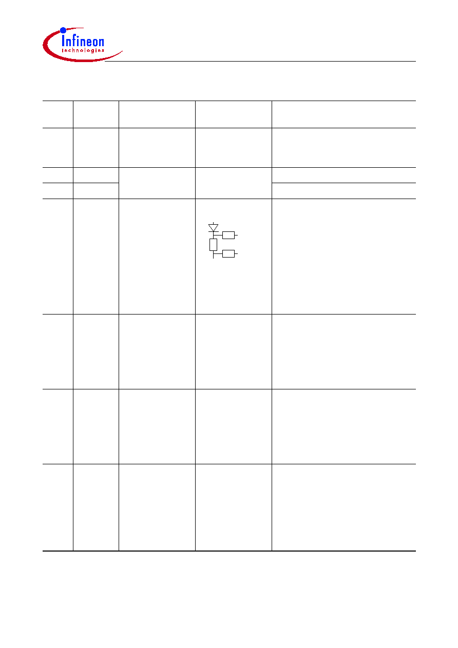
Bias Mon Analog Voltage
Bias Mon-
Bias Mon+
Bias Monitor
This output shows an analog
voltage that is proportional to
the laser bias current. Use this
output to check proper laser
operation and for end of life
indications.
Limit: Bias Current
I
BIAS
< 60 mA
19
20
TxPMon
Analog Voltage
PMon-
PMon+
Tx Power Monitor This output is derived from the
Tx monitor diode
(see
"Application Notes" on
Page 13
).
Output Voltage
V
mon
= 1.2 Ī 0.2 V,
Source Resistance
R
S
= 100 k
MS1/2 MS
N/A
Mounting Studs
Mounting Studs are provided for
transceiver mechanical
attachment to the circuit board.
They also provide an optional
connection of the transceiver to
the equipment chassis ground.
HL1/2/
3/4
HL
N/A
Housing Leads
The transceiver Housing Leads
are provided for additional
signal grounding. The holes in
the circuit board must be
included and be tied to signal
ground (see
"Application
Notes" on Page 13
).
Pin Description (cont'd)
Pin
No.
Symbol
Level/Logic
Function
Description
3 k
3 k
10
I
BIAS
U
10
------------
=
V23818-H18-Lx
Pin Configuration
Data Sheet
4
2001-10-01
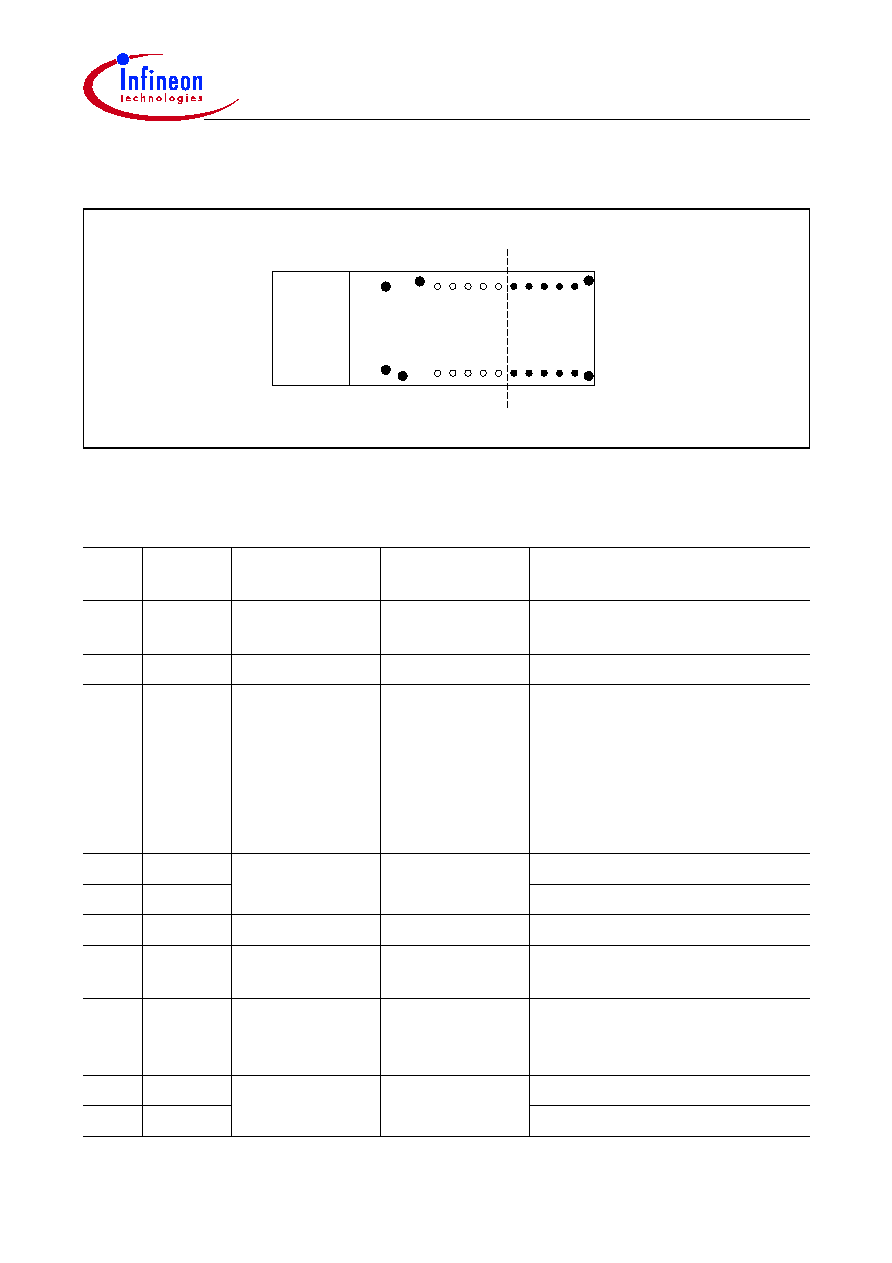
2x5 Transceiver
Figure 2
10 Pin Module
Pin Description
Pin
No.
Symbol
Level/Logic
Function
Description
1
Rx
V
EE
Power Supply
Rx Ground
Negative power supply,
normally ground
2
Rx
V
CC
Power Supply
Rx + 3.3 V
Positive power supply, +3.3 V
3
RxSD
PECL/TTL
Output active
high
Rx Signal
Detect
A high level on this output shows
that optical data is applied to the
optical input.
PECL Output active high for
V23818-H18-L36/L37
TTL Output active high for
V23818-H18-L46/L47
4
RxDn
PECL Output
Rx Output Data
Inverted receiver output data
5
RxD
Receiver output data
6
Tx
V
CC
Power Supply
Tx + 3.3 V
Positive power supply, +3.3 V
7
Tx
V
EE
Power Supply
Tx Ground
Negative power supply,
normally ground
8
TxDis
TTL Input
Tx Disable/
Enable
A low signal switches the laser
on. A high signal switches the
laser off.
9
TxD
PECL Input
Tx Input Data
Transmitter input data
10
TxDn
Inverted transmitter input data
Tx
Rx
HL4
HL1
HL2
HL3
1 2 3 4 5
10 9 8 7 6
10-PIN MODULE - TOP VIEW
MS2
MS1

V23818-H18-Lx
Pin Configuration
Data Sheet
5
2001-10-01
MS1/2 MS
N/A
Mounting Studs
Mounting Studs are provided for
transceiver mechanical
attachment to the circuit board.
They also provide an optional
connection of the transceiver to
the equipment chassis ground.
HL1/
2/3/4
HL
N/A
Housing Leads
The transceiver Housing Leads
are provided for additional
signal grounding. The holes in
the circuit board must be
included and be tied to signal
ground (see
"Application
Notes" on Page 13
).
Pin Description (cont'd)
Pin
No.
Symbol
Level/Logic
Function
Description