Data Sheet
1
2003-01-22
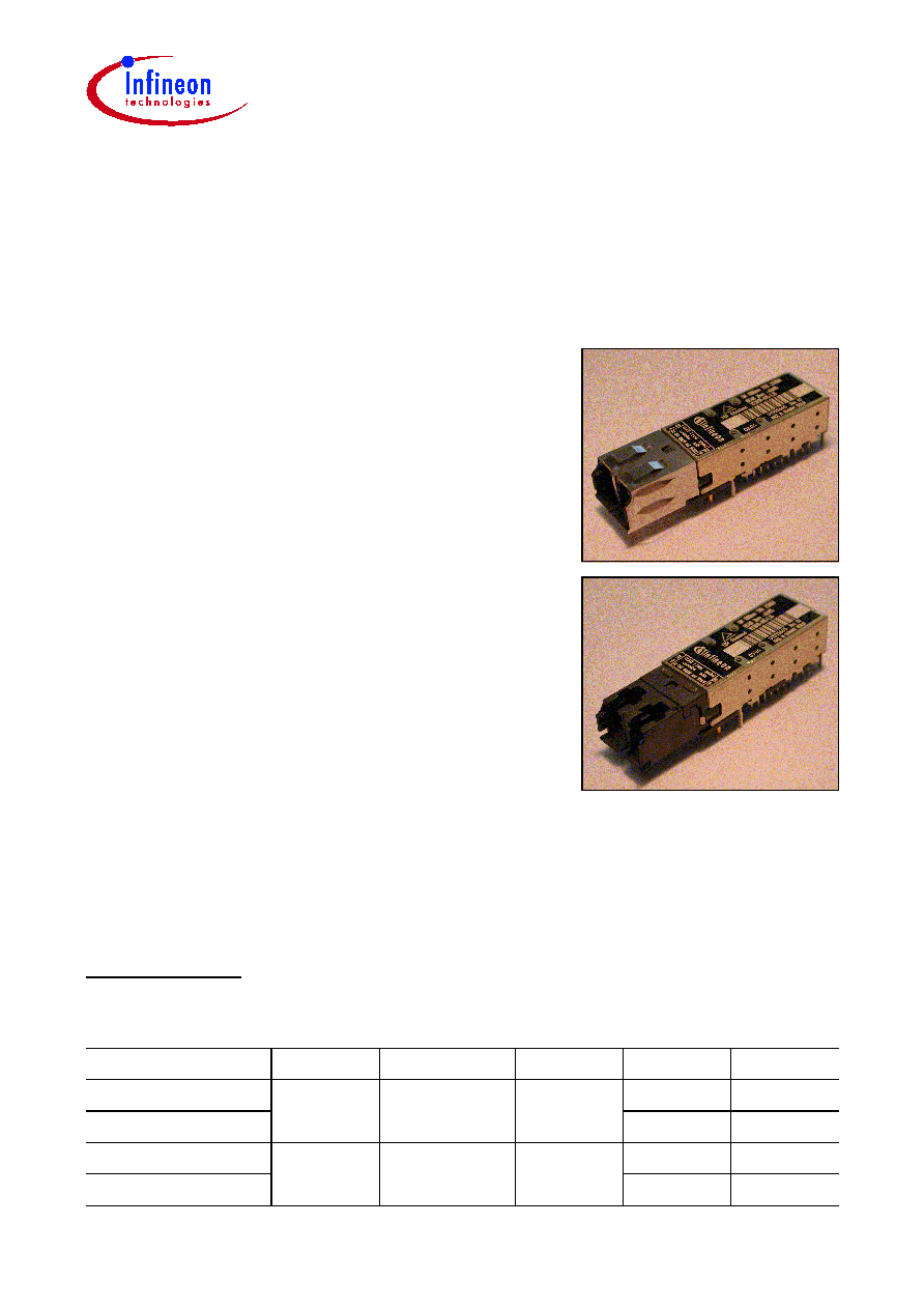
Small Form Factor
Multimode 850 nm 1.0625 GBd Fibre Channel
1.25 Gigabit Ethernet Transceiver
2x5 Pinning with LCTM Connector
V23818-K305-Lxx
Part Number
Voltage
Signal Detect Collar
Input
Output
V23818-K305-L17
3.3 V
LVTTL
yes
DC
DC
V23818-K305-L57
AC
AC
V23818-K305-L15
3.3 V
LVTTL
no
DC
DC
V23818-K305-L55
AC
AC
Fiber Optics
LCTM is a trademark of Lucent
Features
∑ Small Form Factor transceiver
∑ Complies with Fibre Channel and Gigabit Ethernet
standards
∑ Excellent EMI performance
∑ RJ-45 style LCTM connector system
∑ Available with or without collar
∑ Half the size of SC Duplex 1x9 transceiver
∑ Single power supply (3.3 V)
∑ Extremely low power consumption, 445 mW typical
∑ LVPECL differential inputs and outputs
∑ AC/AC coupling in accordance to SFF MSA or optional
DC/DC coupling version
∑ Optimized for 62.5/50 µm graded index fiber
∑ For distances of up to 700 m
∑ Multisource 2x5 footprint
1)
∑ Small size for high port density
∑ UL-94 V-0 certified
∑ ESD Class 1 per MIL-STD 883D Method 3015.7
∑ Compliant with FCC (Class B) and EN 55022
∑ Class 1 FDA and IEC laser safety compliant
1)
Current MSA documentation can be found at www.infineon.com/fiberoptics
V23818-K305-Lxx
Pin Configuration
Data Sheet
2
2003-01-22
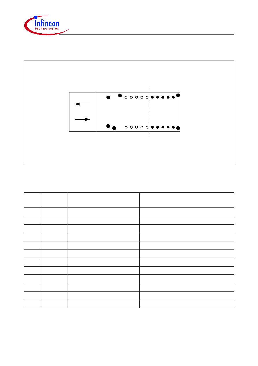
Pin Configuration
Figure 1
Pin Description
Pin
No.
Symbol
Level/Logic
Description
1
V
EEr
Ground
Receiver signal ground
2
V
CCr
Power supply
Receiver power supply
3
SD
LVTTL output
Receiver optical input level monitor
4
RD≠
LVPECL output
Receiver data out bar
5
RD+
LVPECL output
Receiver data out
6
V
CCt
Power supply
Transmitter power supply
7
V
EEt
Ground
Transmitter signal ground
8
TDis
LVTTL input
Transmitter disable
9
TD+
LVPECL input
Transmitter data in
10
TD≠
LVPECL input
Transmitter data in bar
MS
Mounting studs
HL
Housing leads
Tx
Rx
HL
HL
HL
HL
1 2 3 4 5
6
7
8
9
10
TOP VIEW
MS
MS
File: 1331

V23818-K305-Lxx
Pin Configuration
Data Sheet
3
2003-01-22
V
EEr
/
V
EEt
Connect pins 1 and 7 to signal ground.
V
CCr
/
V
CCt
A 3.3 V
DC power supply must be applied at pins 2 and 6. A recommended power supply
filter network is given in the termination scheme. Locate power supply filtering directly at
the transceiver power supply pins. Proper power supply filtering is essential for good EMI
performance.
TD+ / TD≠
Transmitter data LVPECL level inputs. Terminated and AC coupled internally.
RD≠ / RD+
Receiver data LVPECL level outputs. Biased and AC coupled internally.
TDis
A logical LVTTL high input will disable the laser. To enable the laser, an LVTTL low input
must be applied. Leave pin unconnected if feature not required.
SD
LVTTL output. A logical high output indicates normal optical input levels to the receiver.
Low optical input levels at the receiver result in a low output. Signal Detect can be used
to determine a definite optical link failure; break in fiber, unplugging of a connector, faulty
laser source. However it is not a detection of a bad link due to data-related errors.
MS
Mounting studs are provided for transceiver mechanical attachment to the circuit board.
They also provide an optional connection of the transceiver to the equipment chassis
ground. The holes in the circuit board must be tied to chassis ground.
HL
Housing leads are provided for additional signal grounding. The holes in the circuit board
must be included and tied to signal ground.

V23818-K305-Lxx
Description
Data Sheet
4
2003-01-22
Description
The Infineon Gigabit Ethernet multimode transceiver ≠ part of Infineon Small Form
Factor transceiver family ≠ is based on and compliant to the Physical Medium Depend
(PMD) sublayer and baseband medium, type 1000-Base-SX (short wavelength) as
specified in IEEE 802.3 and Fibre Channel FC-PI Rev. 13 100-M5-SN-I, 100-M6-SN-I.
The appropriate fiber optic cable is 62.5 µm or 50 µm multimode fiber with LCTM
connector.
The Infineon Gigabit Ethernet multimode transceiver is a single unit comprised of a
transmitter, a receiver, and an LCTM receptacle. This design frees the customer from
many alignment and PC board layout concerns.
This transceiver supports the LCTM connectorization concept. It is compatible with RJ-45
style backpanels for high end Data Com and Telecom applications while providing the
advantages of fiber optic technology.
The module is designed for low cost SAN, LAN, WAN, Fibre Channel and Gigabit
Ethernet applications. It can be used as the network end device interface in mainframes,
workstations, servers, and storage devices, and in a broad range of network devices
such as bridges, routers, hubs, and local and wide area switches.
This transceiver operates at 1.0625 and 1.25 Gbit/s from a single power supply (+3.3 V).
The full differential data inputs and outputs are LVPECL compatible.
Operating Range over each Optical Fiber Type
Fiber Type
Limit Values
Unit
min.
typ.
max.
62.5 micron MMF
0.5
2 to 300
400
meters
50.0 micron MMF
0.5
2 to 550
700

V23818-K305-Lxx
Description
Data Sheet
5
2003-01-22
Functional Description of 2x5 Pin Row Transceiver
This transceiver is designed to transmit serial data via multimode cable.
Figure 2
Functional Diagram
The receiver component converts the optical serial data into LVPECL compatible
electrical data (RD+ and RD≠). The Signal Detect (SD) shows whether an optical signal
is present.
The transmitter converts LVPECL compatible electrical serial data (TD+ and TD≠) into
optical serial data. Data lines are differentially 100
W
terminated.
The transmitter contains a laser driver circuit that drives the modulation and bias current
of the laser diode. The currents are controlled by a power control circuit to guarantee
constant output power of the laser over temperature and aging.
The power control uses the output of the monitor PIN diode (mechanically built into the
laser coupling unit) as a controlling signal, to prevent the laser power from exceeding the
operating limits.
Single fault condition is ensured by means of an integrated automatic shutdown circuit
that disables the laser when it detects laser fault to guarantee the laser Eye Safety.
The transceiver contains a supervisory circuit to control the power supply. This circuit
makes an internal reset signal whenever the supply voltage drops below the reset
threshold. It keeps the reset signal active for at least 140 milliseconds after the voltage
has risen above the reset threshold. During this time the laser is inactive.
A low signal on TxDis enables transmitter. If TxDis is high the transmitter is disabled.
Laser
Driver
Laser
Monitor
Power
Control
Receiver
SD
TD+
RD+
RD
-
TD
-
Tx
Coupling Unit
Rx
Coupling Unit
e/o
o/e
o/e
TxDis
LEN
File: 1358
Automatic
Shut-Down
Multimode Fiber