Preliminary Product Information
1
2004-02-13
1x9 Transceiver with Duplex SC Receptacle
Single Mode 1300 nm 21 km
SONET OC-3 / SDH STM-1
V23836-C18-C63
V23836-C18-C363
Preliminary Data Sheet
File: 1161
Part Number
Voltage
V23836-C18-C63
5 V
V23836-C18-C363
3.3 V
Fiber Optics
Features
∑ Compliant with ATM, SONET OC-3, SDH STM-1
∑ Industry standard multisource 1x9 footprint
∑ Meets mezzanine standard height of 9.8 mm
∑ Compact integrated transceiver unit with
≠ FP (Fabry Perot) laser diode transmitter
≠ InGaAs PIN photodiode ≠ TIA receiver
≠ Duplex SC receptacle
∑ Standard operating temperature range of 0∞C to 70∞C
∑ Class 1 FDA and IEC laser safety compliant
∑ Single power supply (5 V or 3.3 V)
∑ Signal detect indicator (PECL)
∑ PECL differential (DC-coupled) inputs and outputs
∑ Process plug included
∑ Input Signal Monitor
∑ Wave solderable and washable with process plug inserted
∑ For distances of up to 21 km on single mode fiber
∑ 1x9 evaluation board V23806-S84-Z5 available upon request
V23836-C18-C63
V23836-C18-C363
Pin Configuration
Preliminary Product Information
2
2004-02-13
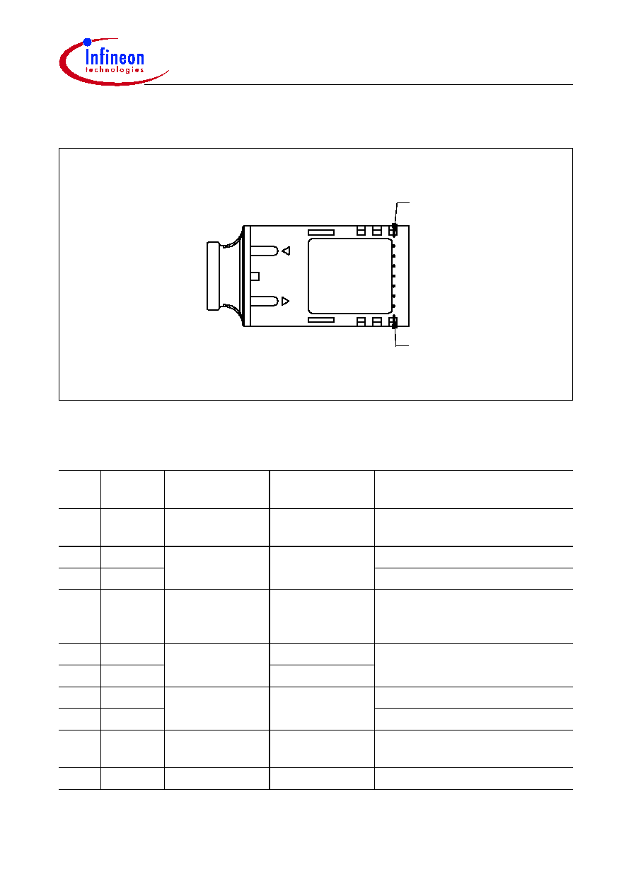
Pin Configuration
Figure 1
Pin Description
Pin
No.
Symbol
Level/Logic
Function
Description
1
V
EE
Rx
Power Supply
Rx Ground
Negative power supply,
normally ground
2
RD+
PECL Output
Rx Output Data
Receiver output data
3
RD≠
Inverted receiver output data
4
SD
PECL
Rx Signal
Detect
A high level on this output shows
that optical data is applied to the
optical input.
5
V
CC
Rx
Power Supply
Rx 5 V/3.3 V
Positive power supply, 5 V/3.3 V
6
V
CC
Tx
Tx 5 V/3.3 V
7
TD≠
PECL Input
Tx Input Data
Inverted transmitter input data
8
TD+
Transmitter input data
9
V
EE
Tx
Power Supply
Tx Ground
Negative power supply,
normally ground
S1/2
Mech. Support
Stud Pin
Not connected
Pin 9
Pin 1
Top view
File: 1343

V23836-C18-C63
V23836-C18-C363
Description
Preliminary Product Information
3
2004-02-13
Description
The Infineon single mode ATM transceiver complies with the ATM Forum's Network
Compatible ATM for Local Network Applications document and ANSI's Broadband
ISDN - Customer Installation Interfaces, Physical Media Dependent Specification,
T1.646-1995, Bellcore - SONET OC-3 IR-1 and ITU-T G.957 STM-1 S-1.1.
ATM was developed to facilitate solutions in multimedia applications and real time
transmission. The data rate is scalable, and the ATM protocol is the basis of the
broadband public networks being standardized in the International Telecommunications
Union (ITU), the former International Telegraph and Telephone Consultative Committee
(CCITT). ATM can also be used in local private applications.
The Infineon single mode ATM transceiver is a single unit comprised of a transmitter, a
receiver, and an SC receptacle. This design frees the customer from many alignment
and PC board layout concerns. The module is designed for low cost WAN applications.
It can be used as the network end device interface in workstations, servers, and storage
devices, and in a broad range of network devices such as bridges, routers, and intelligent
hubs, as well as wide area ATM switches.
This transceiver operates at 155.520 Mbit/s from a single power supply (5 V or 3.3 V).
The differential data inputs and outputs are DC-coupled and PECL compatible.
Supported Link Lengths
Category within Standard
Reach
Unit
min.
max.
1)
1)
Maximum reach over fiber type SM-G.652 as defined by ITU-T G.957 and Telcordia GR-253-CORE standards.
Longer reach possible depending upon link implementation.
SDH STM S-1.1
0
15,000
meters
SONET OC-3 IR-1
0
21,000

V23836-C18-C63
V23836-C18-C363
Description
Preliminary Product Information
4
2004-02-13
Functional Description
This transceiver is designed to transmit serial data via single mode fiber.
Figure 2
Functional Diagram
The receiver component converts the optical serial data into PECL compatible electrical
data (RD+ and RD≠). The Signal Detect (SD, active high) shows whether optical data is
present
1)
.
The transmitter converts electrical PECL compatible serial data (TD+ and TD≠) into
optical serial data.
The transmitter contains a laser driver circuit that drives the modulation and bias current
of the laser diode. The currents are controlled by a power control circuit to guarantee
constant output power of the laser over temperature and aging.
The power control uses the output of the monitor PIN diode (mechanically built into the
laser coupling unit) as a controlling signal, to prevent the laser power from exceeding the
operating limits.
Single fault condition is ensured by means of an integrated automatic shutdown circuit
that disables the laser when it detects transmitter failures or when
V
CC
is too high. A reset
is only possible by turning the power off, and then on again.
1)
We recommend to switch off the transmitter supply (
V
CC
Tx) if no transmitter input data is applied.
Laser
Driver
Laser
Monitor
Power
Control
Receiver
SD
TD+
RD+
RD
-
TD
-
Tx
Coupling Unit
Rx
Coupling Unit
e/o
o/e
o/e
File: 1365
Automatic
Shut-Down
Single
Mode
Fiber

V23836-C18-C63
V23836-C18-C363
Description
Preliminary Product Information
5
2004-02-13
Regulatory Compliance
Feature
Standard
Comments
ESD:
Electrostatic Discharge
to the Electrical Pins
MIL-STD 883D
Method 3015.7
JESD22-A114-B
Class 1 (> 1000 V) HBM
Class 1C
Immunity:
Electrostatic Discharge
(ESD) to the Duplex SC
Receptacle
EN 61000-4-2
IEC 61000-4-2
Discharges of
±
15 kV with an air
discharge probe on the receptacle
cause no damage.
Immunity:
Radio Frequency
Electromagnetic Field
EN 61000-4-3
IEC 61000-4-3
With a field strength of 3 V/m, noise
frequency ranges from 10 MHz to
2 GHz. No effect on transceiver
performance between the
specification limits.
Emission:
Electromagnetic
Interference (EMI)
FCC 47 CFR Part 15
Class B
EN 55022 Class B
CISPR 22
Noise frequency range:
30 MHz to 18 GHz;
Margins depend on PCB layout and
chassis design.