LCTM is a trademark of Lucent.
Part Number
Chassis/Signal Grounding Concept
V23839-R35-L55
Common
V23839-R36-L55
Separated
Preliminary Product Information
1
2004-06-25
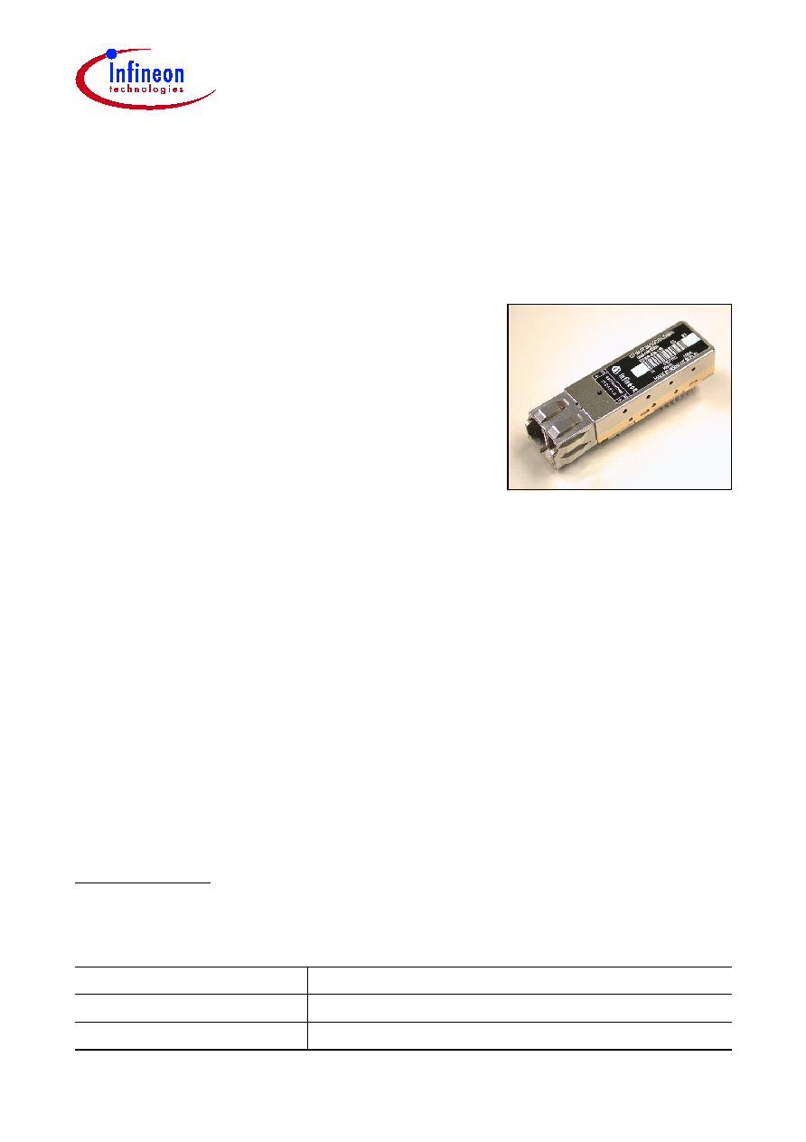
iSFF - Intelligent Small Form Factor
1.25 Gigabit Ethernet (1000 Base-SX)
4.25/2.125/1.0625 Gbit/s Fibre Channel (400/200/100-M5/M6-SN-I)
Multimode 850 nm Transceiver with LCTM Connector
Preliminary Data Sheet
File: 1145
Fiber Optics
V23839-R3x-L55
Features
∑ Based on Small Form Factor (SFF) MSA
1)
∑ Fully SFF-8472 compatible
∑ Incorporating Intelligent ≠ Digital Diagnostic
Monitoring Interface
∑ Internal calibration implementation
∑ Excellent EMI performance
∑ Separate and common chassis/signal ground
module concepts available
∑ 2x7 footprint
∑ RJ-45 style LCTM connector system
∑ Single power supply (3.3 V)
∑ Extremely low power consumption of 530 mW typical
∑ Small size for high port density
∑ UL-94 V-0 certified
∑ ESD Class 1C per JESD22-A114-B (MIL-STD 883D Method 3015.7)
∑ According to FCC (Class B) and EN 55022
∑ For distances of up to 860 m (50 µm fiber)
∑ Laser safety according to Class 1 FDA and IEC
∑ Internally AC/AC coupled
∑ Operating temperature range of ≠20∞C to 85∞C
∑ iSFF evaluation kit available upon request
1)
MSA documentation can be found at
www.infineon.com/fiberoptics
under Transceivers, SFF Transceivers.

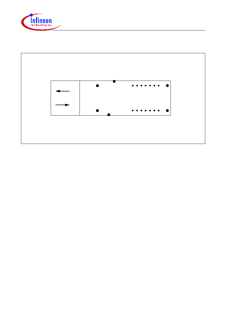
V23839-R3x-L55
Pin Configuration
Preliminary Product Information
3
2004-06-25
Pin Description
Pin No.
Name
Logic Level
Function
1
V
EE
R
N/A
Receiver Ground
2
V
CC
R
N/A
Receiver Power
3
SD
LVTTL
Signal Detect
1)
5)
4
RD≠
LVPECL
Inv. Received Data Out
2)
5
RD+
LVPECL
Received Data Out
2)
6
V
CC
T
N/A
Transmitter Power
7
V
EE
T
N/A
Transmitter Ground
8
TxDis
LVTTL
Transmitter Disable
3)
9
TD+
LVPECL
Transmit Data In
4)
10
TD≠
LVPECL
Inv. Transmit Data In
4)
A
SDA
LVTTL
2-wire Data Interface
5)
B
SCL
LVTTL
2-wire Clock Interface
5)
C
Rate Select
6)
LVTTL
1 & 2 or 2 & 4 Gbit/s
7)
D
Tx Fault
LVTTL
Transmitter Fault
5)
MS
MS
N/A
Mounting Studs
8)
HL
HL
N/A
Housing Leads
9)
1)
Normal operation: Logic 1 output, represents that light is present at receiver input.
Fault condition: Logic 0 output.
2)
AC coupled inside transceiver. Must be terminated with 100
differential at the user SERDES.
3)
A logic 0 switches the transmitter on. A logic 1 switches the transmitter off.
4)
AC coupled and 100
differential termination inside the transceiver.
5)
Should be pulled up on host board to
V
CC
by 4.7 - 10 k
.
6)
Not implemented.
7)
In accordance to SFF Committee SFF-8079 Draft.
8)
Mounting Studs are provided for transceiver mechanical attachment to the circuit board. They also provide an
optional connection of the transceiver to the equipment chassis ground.
9)
The transceiver Housing Leads are provided for additional signal grounding. The holes in the circuit board must
be included and be tied to signal ground (see
EMI Recommendations
).

V23839-R3x-L55
Description
Preliminary Product Information
4
2004-06-25
Description
The Infineon Fibre Channel multimode transceiver ≠ part of Infineon iSFF family ≠ is
compatible to the Physical Medium Depend (PMD) sublayer and baseband medium,
type 1000 Base-SX (short wavelength) as specified in IEEE Std 802.3 and Fibre Channel
FC-PI-2 (Rev. 5.0) 400-M5-SN-I, 400-M6-SN-I for 4.25 Gbit/s,
FC-PI-2 (Rev. 5.0) 200-M5-SN-I, 200-M6-SN-I for 2.125 Gbit/s, and
FC-PI-2 (Rev. 5.0) 100-M5-SN-I, 100-M6-SN-I for 1.0625 Gbit/s.
The appropriate fiber optic cable is 62.5 µm or 50 µm multimode fiber with LCTM
connector.
V23839-R3x-L55
Description
Preliminary Product Information
5
2004-06-25
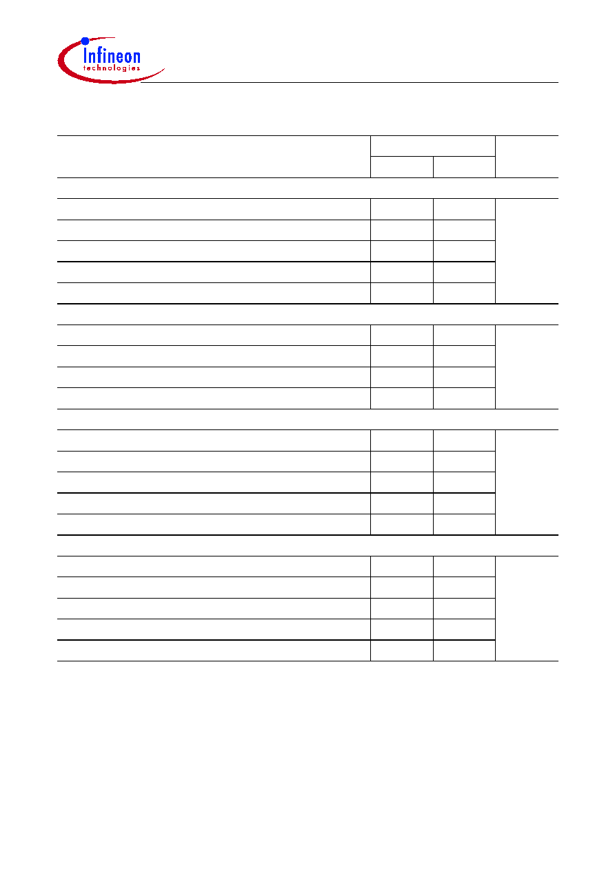
Link Length as Defined by IEEE and Fibre Channel Standards
Fiber Type
Reach
Unit
min.
1)
max.
2)
at 1.0625 Gbit/s
50 µm, 2000 MHz*km
0.5
860
meters
50 µm, 500 MHz*km
0.5
500
50 µm, 400 MHz*km
0.5
450
62.5 µm, 200 MHz*km
0.5
300
62.5 µm, 160 MHz*km
0.5
250
at 1.25 Gbit/s
50 µm, 500 MHz*km
2
550
meters
50 µm, 400 MHz*km
2
500
62.5 µm, 200 MHz*km
2
275
62.5 µm, 160 MHz*km
2
220
at 2.125 Gbit/s
50 µm, 2000 MHz*km
0.5
500
meters
50 µm, 500 MHz*km
0.5
300
50 µm, 400 MHz*km
0.5
260
62.5 µm, 200 MHz*km
0.5
150
62.5 µm, 160 MHz*km
0.5
120
at 4.25 Gbit/s
50 µm, 2000 MHz*km
0.5
270
meters
50 µm, 500 MHz*km
0.5
150
50 µm, 400 MHz*km
0.5
130
62.5 µm, 200 MHz*km
0.5
70
62.5 µm, 160 MHz*km
0.5
55
1)
Minimum reach as defined by IEEE and Fibre Channel Standards. A 0 m link length (loop-back connector) is
supported.
2)
Maximum reach as defined by IEEE and Fibre Channel Standards. Longer reach possible depending upon link
implementation.