Data Sheet
1
2002-08-28
40 Channel MUX/DEMUX
with Internal Temperature Controller
V23845-A/Bwxyz
Preliminary Data
Fiber Optics
Part Number
Description
Type of Component
V23845-
A
DEMUX
B
MUX
w
Wavelength Range
1
C-Band
4
L-Band
x
Number of Channels
1
8
2
16
3
24
4
32
5
40
6
> 40 on request
y
Channel Spacing
1
200
2
100
3
50 on request
z
Design Options
1 Low Loss
2 Flat Top
Features
∑ Small housing
∑ Internal temperature controller
∑ UL-94 listed
Compliance
∑ EN 181 00
∑ Telcordia GR-1209, GR-1221
∑ ETSI ES 300 671
Types of Components
MUX
DEMUX-LL DEMUX-FT
C-Band (first channel 192.0 THz)
X
X
X
L-Band (first channel 186.7 THz)
X
X
X

V23845-A/Bwxyz
Description
Data Sheet
3
2002-08-28
Description
This specification describes a dense wavelength division multiplexer / demultiplexer to
multiplex / demultiplex a signal consisting of 40 optical channels with a channel spacing
of 100 GHz. The component is realized by a 40-Channel-Arrayed-Waveguide Grating
(AWG).
Module Specifications
1)
1)
All values are specified for all polarizations and operating temperatures in a clear window of 200 pm.
Parameter
Symbol
MUX
DEMUX-LL DEMUX-FT Unit
Number of channels
N
40
Channel spacing
D
f
100
GHz
Nominal center wavelength
l
c
ITU-T grid
Accuracy of channel center
frequency
d
f
3
GHz
Bandwidth @ 1 dB
PB1
40
25
40
Bandwidth @ 3 dB
PB3
50
50
75
Insertion loss
IL
5.5
5.5
8.0
dB
Insertion loss uniformity
D
IL
1.5
Isolation (adjacent channel)
ISO
a
25
24
Isolation
(non-adjacent channel)
ISO
n
32
30
Passband ripple
R
1
0.5
Polarization Dependant Loss PDL
0.5
Optical return loss
ORL
50
Max. opt. power
P
max
20
dBm
Storage temperature
T
s
≠40...85
∞C
Operation temperature
T
op
0...70
Type of temperature
stabilization
Heater
Heater Power
P
H
6
W
Set point of Heater
T
set
75
4
∞C
Type of temperature sensor
RTD
PT 100
W
/∞C
Weight
60
g
Optical interface
connectors upon request
n.a.
Electronic interface
10 pins
n.a.

V23845-A/Bwxyz
Description
Data Sheet
4
2002-08-28
Figure 2
Isolation
Definitions
Number of channels
N
Channel Spacing
d
f
Frequency difference between adjacent
channels
Clear Window
CW
Centred at ITU and equal to 200 pm
1 dB Bandwidth
PB1
Width of port n at IL
peak
≠1 dB
Insertion Loss
IL
Maximum channel loss in Clear Window
IL Uniformity
D
IL
Difference between highest and lowest IL
Polarization Dependant Loss
PDL
Maximum loss variation in Clear Window
due to change of state of polarization
Optical Return Loss
ORL
Ratio of reflected power to incident power
Isolation
ISO
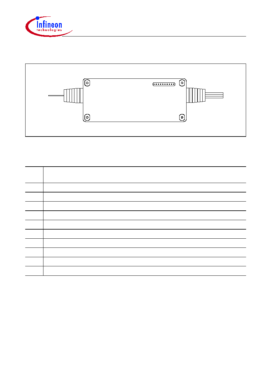
Figure 2
Housing Dimensions
Dimension
Typ.
Unit
Length
120
mm
Width
50
Height
11.5
IL
j max
CW
i-1
CW
i
CW
j
Isolation
adjacent
channels
Isolation
non-adjacent
channels