 | –≠–ª–µ–∫—Ç—Ä–æ–Ω–Ω—ã–π –∫–æ–º–ø–æ–Ω–µ–Ω—Ç: BT8048 | –°–∫–∞—á–∞—Ç—å:  PDF PDF  ZIP ZIP |
TECHNICAL DATA
BT8048
Melody Generator with Accompaniment
FEATURES
û Two Sound Sources with Envelope (CR Envelope)
û Melody is inserted up to two.
û A
ccording to customer's request, the inserted melody is flexible.
û 3.0V to 5.0V Operating Voltage
û DC or AC Triggered Performance Start Mode (Mask Selected)
û Can Drive an 8 Ohm Dynamic Loudspeaker if Provided Externally with
a Transistor
û Bare chip or 8-pin DIP (Plastic) Package available
DESCRIPTION
The BT8048 is a CMOS LSI chip, which plays a prearranged melodies.
ABSOLUTE MAXIMUM RATINGS ( T
a
= 25
o
C )
Characteristic Symbol
Value
Unit
Power Supply Voltage
V
DD
- 0.3 to + 7.0
V
Input Terminal Voltage
V
10
- 0.2 to V
DD
+
0.2 V
Operating Temperature
T
a
-40 to + 85 (V
SS
= 1.5V)
o
C
Storage Temperature
T
stg
- 65 to + 150
o
C
Soldering Temperature and Time
T
sol
260
o
C, 10s (at lead)
ELECTRICAL CHARACTERISTICS
(V
DD
= 5V, T
a
= 25
o
C; unless otherwise specified)
Characteristic Symbol
Test
Condition Min
Typ
Max
Unit
Operating Voltage
V
DD
3.0
5.0
5.5
V
Input Voltage
"1"
V
IH
V
DD
- 0.3
-
V
DD
V
"0"
V
IL
V
SS
-
V
SS
+ 0.3
MT Power Supply Time
150
ms
Response Time
600
ms
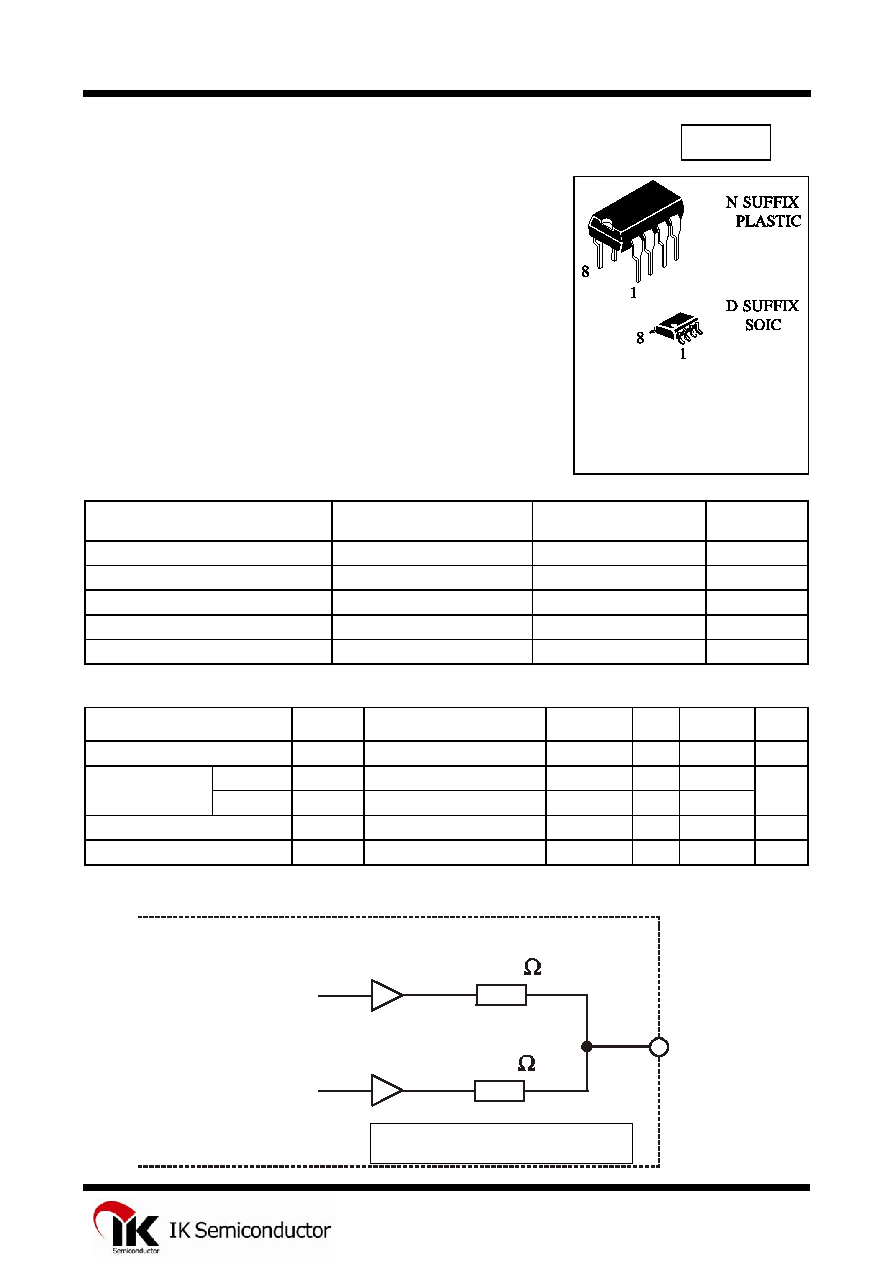
MO OUTPUT PIN EQUIVALENT CIRCUIT
ORDERING INFORMATION
BT8048N Plastic
BT8048D SOIC
T
A
= -40
ú to 85ú C for all packages
Accompaniment
Main Melody
MO Pin
Inside of BT8032
130k
150k
Inside of BT8048
1
BT8048
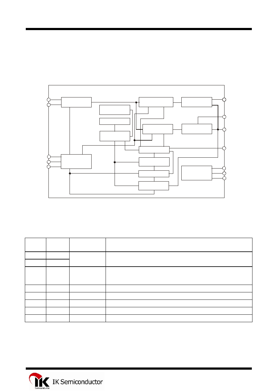
BLOCK DIAGRAM
OSCILLATOR
CONTROL
DRIVER
RHYTHM
ROM
MELODY
ROM
ENVELOPE
MIXER
TEMPO ROM
MELODY ROM
ADDRESS
COUNTER
CONTROL ROM
TONE
GENERATOR
RHYTHM
GENERATOR
ENVELOPE
MIXER
ACCOMPANMENT
GENERATOR
OSC1
SEL1
P1
SEL2
OUT1
MT
OUT2
ENV1
MO
B/ E
ENV2
OSC2
PIN DESCRIPTION
Pin. No.
Pin Name
Pull-Down
Resistor
Functions
1
OSC1
-
A resistor is connected between both terminals to from a ring
2
OSC2
-
oscillator, or external reference signals are applied to OSC1.
3
SEL1 Provided
For binary selection: this Terminal in Conjunction with SEL1, selects a Melody.
For direct selection: Selects Melody 2 and Controls Start and Stop of it's
Performance.
4
V
SS
-
Power Supply Terminal (0V).
5
ENV1
-
Connects Resistor and Capacitor to add Envelope to Main Melody.
6
ENV2
-
Connects Resistor and Capacitor to add Envelope to Accompaniment.
7
MO
-
Output Terminal or Acoustic Signals that have not been Amplified.
8
V
DD
-
3.0V to 5.0V Operating Voltage
2
BT8048
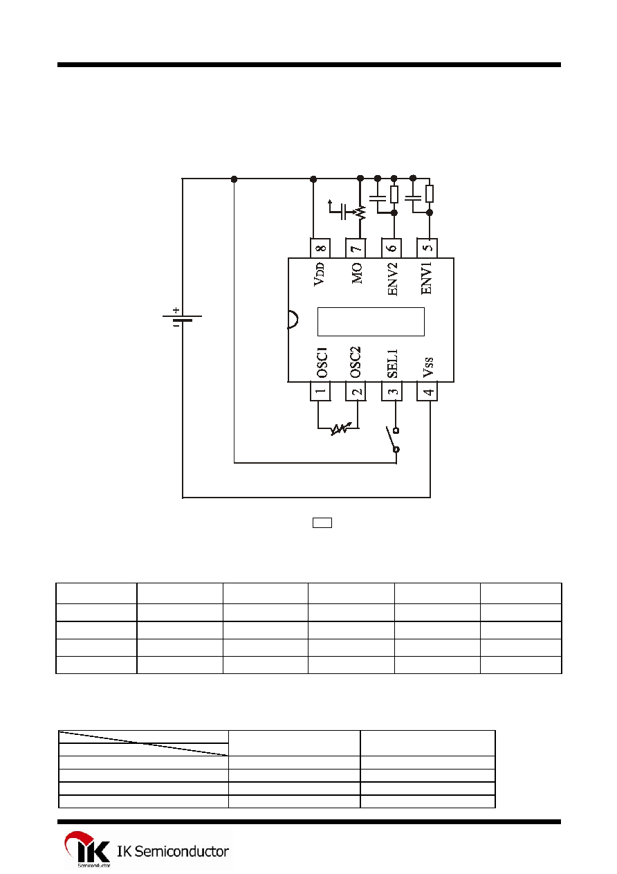
APPLICATION CIRCUIT (basic external connection)
VR1
VR2
C3
LINE
OUT
C2
C1 R1
R2
BT8032
û CR Oscillation, DC Input
RECOMMENDED CONDITIONS FOR EXTERNAL DEVICES
Symbol Ratings Unit Symbol Ratings Unit
VR1
1 - 2
M
C1 4.7
F
VR2 50 k
C2 4.7
F
R1 100 k
C3 0.1
F
R2 100 k
- - -
MELODY SELECT TABLE
Switch
Melody
SEL1 SEL2
Gong OFF
OFF
Bong ON
OFF
Up OFF
ON
Down ON
ON
BT8048
3
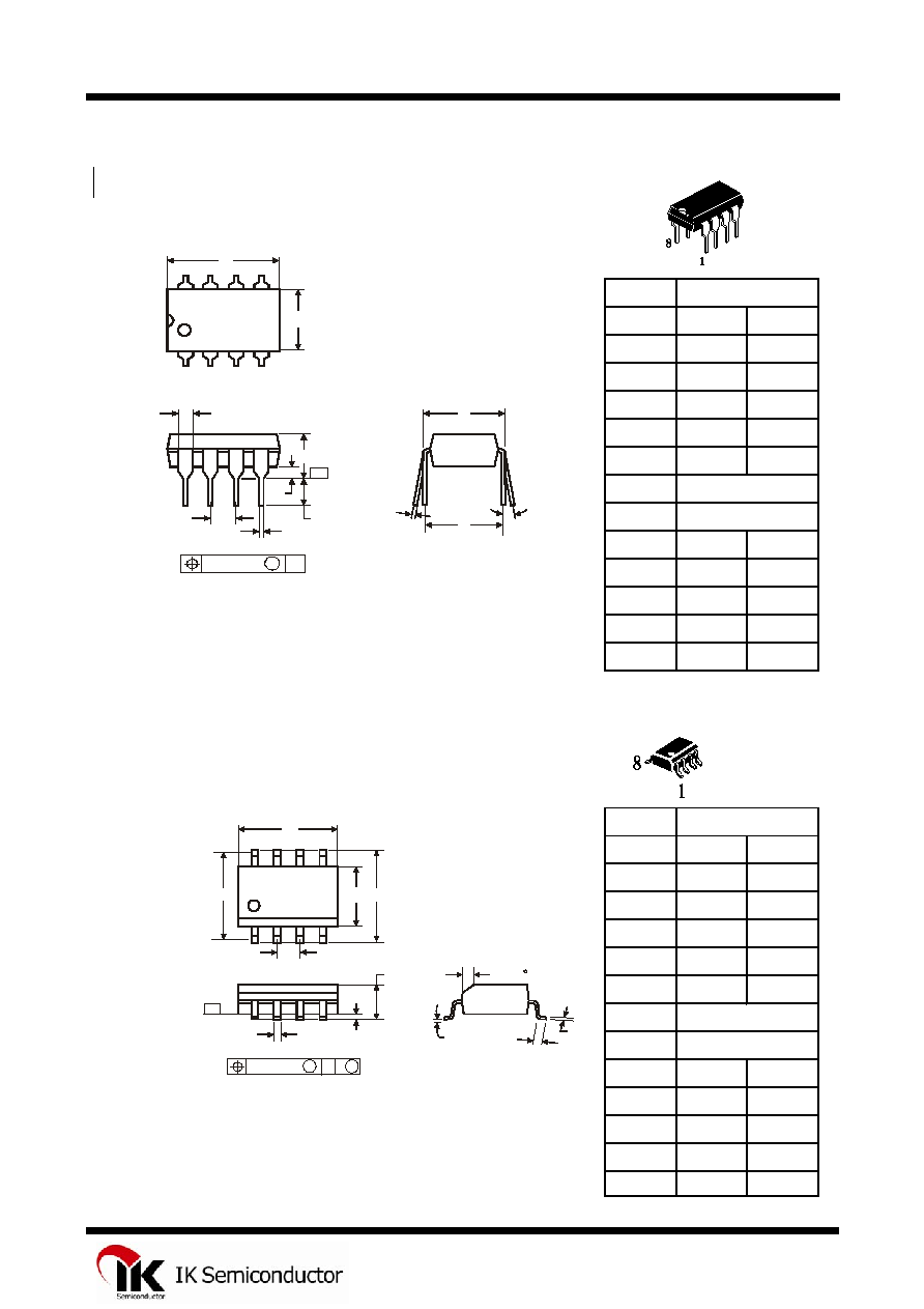
BT8048
N SUFFIX PLASTIC DIP
(MS - 001BA)
Symbol
MIN
MAX
A
8.51
10.16
B
6.1
7.11
C
5.33
D
0.36
0.56
F
1.14
1.78
G
H
J
0ú
10ú
K
2.92
3.81
NOTES:
L
7.62
8.26
1.
Dimensions "A", "B" do not include mold flash or protrusions.
M
0.2
0.36
Maximum mold flash or protrusions 0.25 mm (0.010) per side.
N
0.38
D SUFFIX SOIC
(MS - 012AA)
Symbol
MIN
MAX
A
4.8
5
B
3.8
4
C
1.35
1.75
D
0.33
0.51
F
0.4
1.27
G
H
J
0ú
8ú
NOTES:
K
0.1
0.25
1.
Dimensions A and B do not include mold flash or protrusion.
M
0.19
0.25
2.
Maximum mold flash or protrusion 0.15 mm (0.006) per side
P
5.8
6.2
for A; for B 0.25 mm (0.010) per side.
R
0.25
0.5
1.27
5.72
Dimension, mm
Dimension, mm
2.54
7.62
A
B
H
C
K
C M
J
F
M
P
G
D
R x 45
SEATING
PLANE
0.25 (0.010) M T
-T-
1
8
4
5
L
H
M
J
A
B
F
G
D
SEATING
PLANE
N
K
0.25 (0.010) M T
-T-
C
1
8
4
5
4