 | –≠–ª–µ–∫—Ç—Ä–æ–Ω–Ω—ã–π –∫–æ–º–ø–æ–Ω–µ–Ω—Ç: IL19006 | –°–∫–∞—á–∞—Ç—å:  PDF PDF  ZIP ZIP |

IL19006
Korzhenevskogo 12, Minsk, 220064, Republic of
Belarus
Fax: +375 (17) 278 28 22,
Phone: +375 (17) 278 07 11, 277 24 70, 277 24 61,
277 69 16
E-mail: office@bms.by
URL: www.bms.by
THREE PHASE POWER/ENERGY METERING IC WITH
INSTANTANEOUS PULSE OUTPUT
FEATURES
û Output frequency represents
the absolute sum of energy on
all three phases
û Performs one, two or three
phase power and energy
measurement
û Meets the IEC 521/1036
Specification requirements for
Class 1 AC Watt hour meters
û Operates over a wide
temperature range
û Current transformers for
sensing
û Excellent long term stability
û Easily adaptable to different
signal levels
û Precision voltage reference on-
chip
û Pin selectable pulse rates
û Support tamper detection
FUNCTIONAL DESCRIPTION:
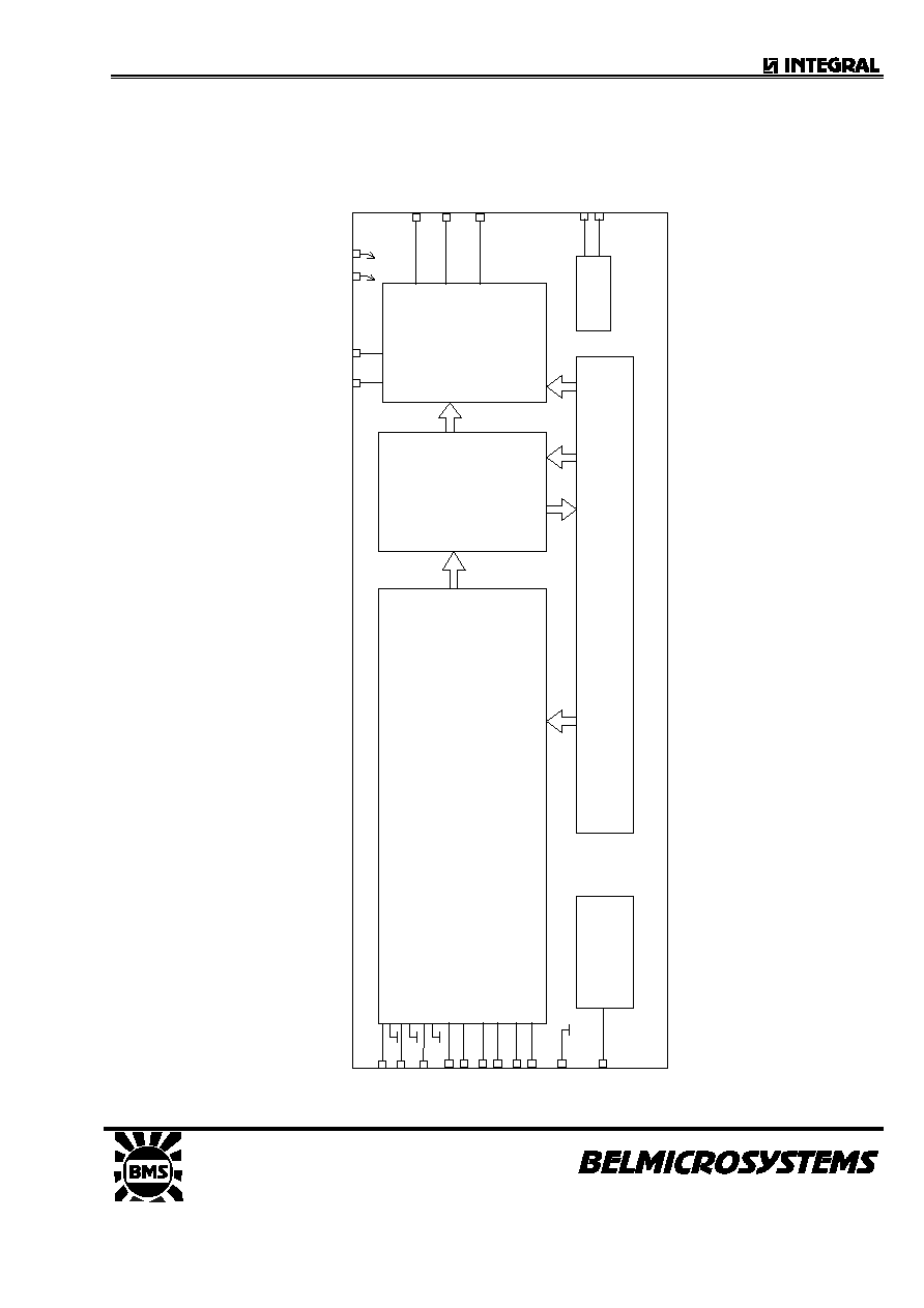
The IL19006 Three Phase Power/Energy metering integrated circuit generates a pulse
rate output, the frequency of which is proportional to the absolute power consumption. The
IL19006 performs the calculations of active power.
The method of calculation takes the power factor into account.
Energy consumption is determined by the power measurement being integrated over time.
The output of this universal three phase power/energy metering integrated circuit, is ideally
suited for applications such as residential and industrial energy metering and control.
The IL19006 Three Phase Power/Energy metering integrated circuit is a CMOS mixed
signal Analog/Digital integrated circuit, which performs three phase power/energy
calculations over a range of 1000:1, to an overall accuracy of better than Class 1.
The integrated circuit includes all the required functions for 3-phase power and energy
measurement such as oversampling A/D converters for the voltage and current sense
inputs, power calculation and energy integration. Internal offsets are eliminated through
the use of cancellation procedures.
The IL19006 generates pulses, the frequency of which is proportional to the power
consumption. Two frequency outputs (FOUT1 and FOUT2) are available. The pulse rate
follows the instantaneous power measured.
ILA19006
Korzhenevskogo 12, Minsk, 220064, Republic of
Belarus
Fax: +375 (17) 278 28 22,
Phone: +375 (17) 278 07 11, 212 24 70, 212 24 61,
212 69 16
E-mail: office@bms.by
URL: www.bms.by
BLOCK DIAGRAM
PO
W
E
R
TO
PULS
E
RATE
IN
T
E
G
.
&
AVERAGE
ANALO
G
SIGNAL
PR
O
C
E
S
S
I
N
G
OSC
TIM
I
NG &
CO
NTRO
L
VREF
V
SS
PG
M
1
PG
M
0
V
DD
IVN2
IVN1
IVN3
F
OUT
1
IIP
1
F
OUT
2
IIN1
DIR
OS
C1
OS
C2
IIP
2
IIN2
IIN3
IIP
3
GND
VR
EF

ILA19006
Korzhenevskogo 12, Minsk, 220064, Republic of
Belarus
Fax: +375 (17) 278 28 22,
Phone: +375 (17) 278 07 11, 212 24 70, 212 24 61,
212 69 16
E-mail: office@bms.by
URL: www.bms.by
ABSOLUTE MAXIMUM RATINGS
*
Parameter
Symbol
Min
Max
Unit
Supply Voltage
V
DD
-V
SS
-0.3
6.0
V
Current on any Pin
I
PIN
-150
+150
mA
Storage Temperature T
STG
-40
+125
úC
Operating Temperature
T
O
-40
+85 úC
Current at any pin
I
p
-100
100
mA
* Stresses above those listed under "Absolute Maximum Ratings" may cause permanent
damage to the device. This is a stress rating only. Functional operation of the device at
these or any other conditions above those indicated in the operation sections of this
specification, is not implied. Exposure to Absolute Maximum Ratings for extended periods
may affect device reliability.
ELECTRICAL CHARACTERISTICS
(V
DD
=2.5V, V
SS
=-2.5V, over the temperature range -10úC to +70úC, unless otherwise specified.)
Parameter
Symbol Min
Typ Maxf Uni
Condition
Operating Temperature
Ranges
T
O
-25
+85
0
C
Supply Voltage
V
DD
-V
SS
4.5
5.5 V
Supply Current
I
DD
15
mA
Nonlinearity of Power
Calculation
-0.3
+0.3
% 1%-100% of rated
power
Current Sensor Inputs
(Differential)
Input Current Range
I
II
-25
+25
A Peak value
Voltage Sensor Inputs
(Asymmetric)
Input Current Range
I
IV
-25
+25
A Peak value
Pins FOUT1, FOUT2,
DIR
Output Low Voltage
Output High Voltage
V
OL
V
OH
V
DD
-1
V
SS
+
1
V
V
I
OL
=5 mA
I
OH
=-2 mA
Pulse Rate: FOUT1
fp
10
1160
3000
Hz
Hz
Specified linearity
Min and max
limits
FOUT2
User
selectable
Oscillator Recommended
crystal:
TV colour burst crystal, f=3.5795 MHz
Pin VREF
Ref. Current
Ref. Voltage
-I
R
V
R
45
1.1
50
55
1.3
A
V
With R = 24 k
connected to V
SS
Referred to V
SS

ILA19006
Korzhenevskogo 12, Minsk, 220064, Republic of
Belarus
Fax: +375 (17) 278 28 22,
Phone: +375 (17) 278 07 11, 212 24 70, 212 24 61,
212 69 16
E-mail: office@bms.by
URL: www.bms.by
PIN DESCRIPTION
Pin Designation
Description
16 GND
Ground
6
VDD
Positive Supply Voltage
14
VSS
Negative Supply Voltage
17
IVN1
Analog Input for Voltage: Phase 1
20
IVN2
Analog Input for Voltage: Phase 2
3
IVN3
Analog Input for Voltage: Phase 3
19
IIN1
Inputs for current sensor-: Phase 1
18 IIP1
2
IIN2
Inputs for current sensor : Phase 2
1 IIP2
5
IIN3 .
Inputs for current sensor: Phase 3
4 IIP3
10
OSC1
Connections for crystal or ceramic resonator
11
OSC2
(OSC1=Input; OSC2=Output)
7
FOUT1
Pulse rate outputs
8 FOUT2
.
9 DIR
Direction
indicator
12
PGM0
FOUT2 Frequency select pins
13 PGM1
15
VREF
Connection for current setting resistor
Note: arrangement of pins according to analog SA9605A (Sames)
FUNCTIONAL DESCRIPTION
The IL19006 is a CMOS mixed signal Analog/Digital integrated circuit, which
performs three phase power/energy calculations over a range of 1000:1, to an overall
accuracy of better than Class 1.
The IL19006 in both DIP-20 and SOIC-20 package options is functionally similar to the
SA9105E and SA9105F with the advantage of no external loop capacitors.
The integrated circuit includes all the required functions for 3-phase power and energy
measurement such as oversampling A/D converters for the voltage and current sense
inputs, power calculation and energy integration. Internal offsets are eliminated through the
use of cancellation procedures.
The IL19006 generates pulses, the frequency of which is proportional to the power
consumption. Two frequency outputs (FOUT1 and FOUT2) are available. The pulse rate
follows the instantaneous power measured.
1. Power Calculation
In the Application Circuit (Figure 1), the mains voltages from Line 1, Line 2 and Line
3, are converted to currents and applied to the voltage sense inputs IVN1, IVN2 and

ILA19006
Korzhenevskogo 12, Minsk, 220064, Republic of
Belarus
Fax: +375 (17) 278 28 22,
Phone: +375 (17) 278 07 11, 212 24 70, 212 24 61,
212 69 16
E-mail: office@bms.by
URL: www.bms.by
IVN3.
The current levels on the voltage sense inputs are derived from the mains voltage
(3 x 230 VAC) being divided down through voltage dividers to 14V. The resulting
input currents into the A/D converters are 14
A through the resistors R
15
, R
16
and
R
17
.
For the current sense inputs the voltage drop across the current transformers
terminating resistors are converted to currents of 16
A for rated conditions, by
means of resistors R
8
, R
9
(Phase 1); R
10
, R
11
(Phase 2); and R
12
, R
13
(Phase 3).
The signals providing the current information are applied to the current sensor inputs: IIN1,
IIP1; IIN2, IIP2; and IIN3, IIP3.
In this configuration, with the mains voltage of 3 x 230 V and rated currents of 80A,
the output frequency of the IL19006 energy metering integrated circuit at FOUT1
is 1.16kHz. In this case 1 pulse will correspond to an energy consumption of 3 x 18.4
kW/1160Hz = 47.6 Ws.
The output frequency at FOUT1 and FOUT2 represents the absolute sum of the
energy measured on all three phases, regardless of the direction of energy flow
through the current sensors. This measurement method will assist meter
manufacturers to circumvent meter tampering by reversal of the phases.
2. Analog Input Configuration
The current and voltage sensor inputs are illustrated below.
These inputs are protected against electrostatic discharge through clamping
diodes, in conjunction with the amplifiers input configuration.
The feedback loops from the outputs of the amplifiers A
I
and A
V
generate virtual
shorts on the signal inputs. Exact duplications of the input currents are generated
for the analog processing circuitry.