 | –≠–ª–µ–∫—Ç—Ä–æ–Ω–Ω—ã–π –∫–æ–º–ø–æ–Ω–µ–Ω—Ç: IL33035 | –°–∫–∞—á–∞—Ç—å:  PDF PDF  ZIP ZIP |
IL33035
1
B
RUSHLESS
DC
M
OTOR
C
ONTROLLER
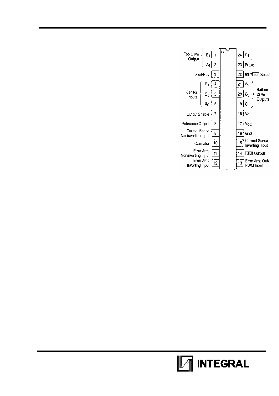
The IL33035 is a high performance second generation
monolithic brushless DC motor controller containing all of
the active functions required to implement a full featured
open loop, three or four phase motor control system. This
device consists of a rotor position decoder for proper
commutation sequencing, temperature compensated
reference capable of supplying sensor power, frequency
programmable sawtooth oscillator, three open collector
top drivers, and three high current totem pole bottom
drivers ideally suited for driving power MOSFETs.
Also included are protective features consisting of
undervoltage lockout, cycle-by-cycle current limiting with a
selectable time delayed latched shutdown mode, internal
thermal shutdown, and a unique fault output that can be
interfaced into microprocessor controlled systems.
Typical motor control functions include open loop speed,
forward or reverse direction, run enable, and dynamic
braking. The MC33035 is designed to operate with
electrical sensor phasings of 60ú/300ú or 120ú/240ú, and
can also efficiently control brush DC motors
F
EATURES
û 10 to 30 V Operation
û Undervoltage Lockout
û 6.25V Reference Capable of Supplying Sensor Power
û Fully Accessible Error Amplifier for Closed Loop Servo Applications
û High Current Drivers Can Control External 3-Phase MOSFET Bridge
û Cycle-By-Cycle Current Limiting
û Pinned-Out Current Sense Reference
û Internal Thermal Shutdown
û Selectable 60ú/300ú or 120ú/240ú Sensor Phasings
û Can Efficiently Control Brush DC Motors with External MOSFET H-Bridge

IL33035
2
A
BSOLUTE MAXIMUM RATINGS
Parameter Symbol
Value
Unit
Power Supply Voltage
Vcc
40
V
Digital Inputs (Pins 3, 4, 5, 6, 22, 23)
-
V
ref
V
Oscillator Input Current (Source or Sink)
Iosc
30
mA
Error Amp Input Voltage Range (Pins 11, 12, Note 1)
V
IR
-0.3 to Vref V
Error Amp Output Current (Source or Sink, Note 2)
I
Out
10
mA
Current Sense Input Voltage Range (Pins 9, 15)
V
Sense
-0.3 to 5.0
V
Fault Output Voltage
V
CE(Fault)
20
V
Fault Output Sink Current
I
Sink(Fault)
20
mA
Top Drive Voltage (Pins 1, 2, 24)
V
CE(top)
40
V
Top Drive Sink Current (Pins 1, 2, 24)
I
Sink(top)
50
mA
Bottom Drive Supply Voltage (Pin 18)
V
C
30
V
Bottom Drive Output Current
(Source or Sink, Pins 19, 20. 21)
I
DRV
100
mA
Power Dissipation and Thermal Characteristics
DIP package Maximum Power Dissipation T
A
= 85
o
C Thermal
Resistance. Junction-to-Air
SO Package Maximum Power Dissipation T
A
= 85
o
C
Thermal Resistance, Junction-to-Air
P
D
R
JA
P
D
R
JA
860
75
650
100
mW
o
C/W
mW
o
C/W
Operating Junction Temperature
TJ
150
o
C
Operating Ambient Temperature Range
TA
-4010+65
o
C
Storage Temperature Range
Tstg
-6510+150
o
C
ELECTRICAL
CHARACTERISTICS
(Vcc = Vc = 20 V, R
-= 4.7 k, C
= 10 nF, T
A
= 25úC, unless ofriarwise noted.)
Characteristic Symbol
Min
Typ
Max
Unit
Reference Output Voltage (I
ref
= 1.0 mA)
T
A
= 25
o
C
T
A
=-40
o
to+85
o
C
V
ref
5.9
5.82
6.24
-
6.5
6.57
V
Line Regulation (Vcc = 10 to 30 V, I
ref
= 1.0 mA)
Reg
line
-
1.5
30
mV
Load Regulation (I
ref
= 1.0 to 20 mA)
Reg
load
- 16 30 mV
Output Short Circuit Current (Note 3)
I
SC
40 75 - mA
Reference Under Voltage Lockout Threshold
V
th
4.0 4.5 5.0 V
Input Offset Voltage (T
A
=-40
o
to+ 85
o
C) V
IO
- 0.4 10 mV
Input Offset Current (T
A
=-40úto +85úC)
I
IO
- 8.9 500
nA
Input Bias Current (T
A
=-40úto +85úC)
I
IB
- -46 -1000
nA
Input Common Mode Voltage Range
V
ICR
(OVtoV^)
V
Open Loop Voltage Gain (V
O
= 3.0 V, R
L
= 15 k)
A
VOL
70 80 - dB
Input Common Mode Rejection Ratio
CMRR
55
86
-
dB
Power Supply Rejection Ratio (Vcc =Vc
= 10 to 30 V)
PSRR
65
105
-
dB

IL33035
3
ELECTRICAL
CHARACTERISTICS
(Vcc = Vc = 20 V, R
-= 4.7 k, C
= 10 nF, T
A
= 25úC, unless otherwise noted.)
Characteristic Symbol
Min
Typ
Max
Unit
Output Voltage Swing
High State (R
L
= 15k to Gnd)
Low State (R
L
=15k to V
ref
)
V
OH
,
V
OL
4.6
-
5.3
0.5
-
1.0
V
Oscillator Frequency
f
osc
22 25 28 kHz
Frequency Change with Voltage (Vcc = 10 to 30 V)
fosc/V
- 0.01
5.0
%
Sawtooth Peak Voltage
V
OSC(P)
- 4.1 4.5 V
Sawtooth Valley Voltage
V
OSC(V)
1.2 1.5 - V
Input Threshold Voltage (Pins 3, 4, 5, 6, 7, 22, 23) High
Stale
Low State
V
IH
V
IL
3.0
-
2.2
1.7
-
0.8
V
Sensor Inputs (Pins 4, 5, 6)
High State Input Current (V
IH
= 5.0 V)
Low State Input Current (V
IL
= 0 V)
I
IL
I
IL
-150
-600
-70
-337
-20
-150
nA
Forward/Reverse, 60ú/120ú Select (Pins 3, 22, 23) High
State Input Current (V
IH
= 5.0 V)
Low State Input Current (V
IL
= 0 V)
I
IL
I
IL
-75
-300
-36
-175
-10
-75
nA
Output Enable High State Input Current (V
IH
= 5.0 V)
I
IH
-60 -29 -10
A
Low btate Input Current (V
IL
=0 V)
I
IL
-60
-29 -10
Threshold Voltage
V
th
85 101 115 mV
Input Common Mode Voltage Range
V
ICR
- 3.0
- V
Input Bias Current
I
IB
-
-0.9 -5.0 nA
Top Drive Output Sink Saturation (I
Sink
= 25 mA)
V
CE(
SAT
)
- 0.5 1.5 V
Top Drive Output Off-State Leakage (V
CE
= 30 V)
I
DRV(leak)
-
0.06
100
nA
Top Drive Output Switching Time (C
L
= 47 pF, R
L
. = 1.0
k)
Rise Time
Fall Time
t
r
t
f
-
107
26
300
300
ns
Bottom
Drive
Output
Voltage
V
High State (Vcc=20V, Vc = 30 V, I
source
= 50 mA) Low
State (Vcc = 20 V, Vc = 30 V, I
sink
=50 mA)
V
OH
V
OL
(Vcc-2.0)
-
(Vcc-1.1)
1.5
-
2.0
Bottom Drive Output Switching Time (C
L
= 1000 pF)
Rise Time
Fall Time
t
r
,
t
f
-
38
30
200
200
ns
Fault Output Sink Saturation (I
sink
= 16 mA)
V
CE(sat)
-
225 500 mV
Fault Output Off-State Leakage (
VCE
= 20 V)
I
FLT(leak)
-
1.0
100
nA
Under Voltage Lockout
Drive Output Enabled (Vcc or Vc Increasing) Hysteresis
V
th(on)
V
H
8.2
0.1
8.9
0.2
10 0.3
V
Power
Supply
Current
Pin 17 (Vcc = Vc= 20 V)
Pin 17 (Vcc = 20V, Vc = 30V)
Pin 18 (Vcc = Vc= 20V)
Pin 18 (Vcc = 20 V, Vc =30V)
I
CC
I
C
,, 12
14
3.5
5.0
16
20
6.0
10
mA