 | –≠–ª–µ–∫—Ç—Ä–æ–Ω–Ω—ã–π –∫–æ–º–ø–æ–Ω–µ–Ω—Ç: IL8560 | –°–∫–∞—á–∞—Ç—å:  PDF PDF  ZIP ZIP |
I N T E G R A L
IL8560
BELMICROSYSTEMS
1
CLOCK CIRCUIT
FEATURES
û LED direct drive by time-sharing
(duplex)
û Wide operating voltage range
û Alarm on a 24-hour basis
û Time format: 12-hour AM/PM and 24-
hour
û On-chip RC-oscillator for battery
backup
û 50Hz or 60Hz is usable as the
reference frequency
û Possible to automatically advance
"hours", "minutes"
û Sleep timer (max. 59 minutes or 1
hour 59 minutes)
û Repeatedly usable snooze
û Power failure indicator
û 900Hz output for alarm tone
û Bare chip or SOP-28 are available
û Pin-to-Pin replacement with Sanyo
LM8560
FUNCTIONS
û Real time display
û Alarm with snooze
û Sleep timer (max. 59 minutes or 1 hour 59
minutes)
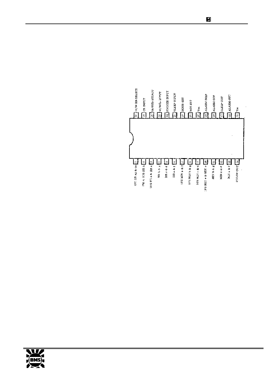
PIN CONNECTION
OPERATION DESCRIPTION
50Hz/60Hz Input:
The on-chip Schmitt trigger circuit allows a simple RC filter at the
input to remove possible line voltage transients. An internal pull-up
resister is provided.
CR Input:
Then AC power-down occurs, the time counter enters the "hold" mode and
the on-chip clock oscillator starts operating immediately. If there is no input at
"50/60 Hz input" during 3-clock period, this oscillator controls the time counter
advance instead of "50/60Hz input". The values of CR determine the
frequency of the on-chip clock oscillator. All segment outputs are off during
backup oscillator operation.
NOTE: If the backup OSC is used at the power-down mode, "50/60Hz
input" must be open or at Vss level.
50/60 select input:
Connecting "50/60Hz select" to Vss enables 50Hz operation. For 60Hz
operation, "50/60Hz select" is left unconnected: Pull-down to V
DD
is provided
by the internal pulldown resister.
Display mode select input
(alarm display/sleep display);
The internal pull-down resistor allows the use of 2 SPST (single-pole single-
throw) switches to select 4 display modes listed in Table 1.
I N T E G R A L
IL8560
BELMICROSYSTEMS
2
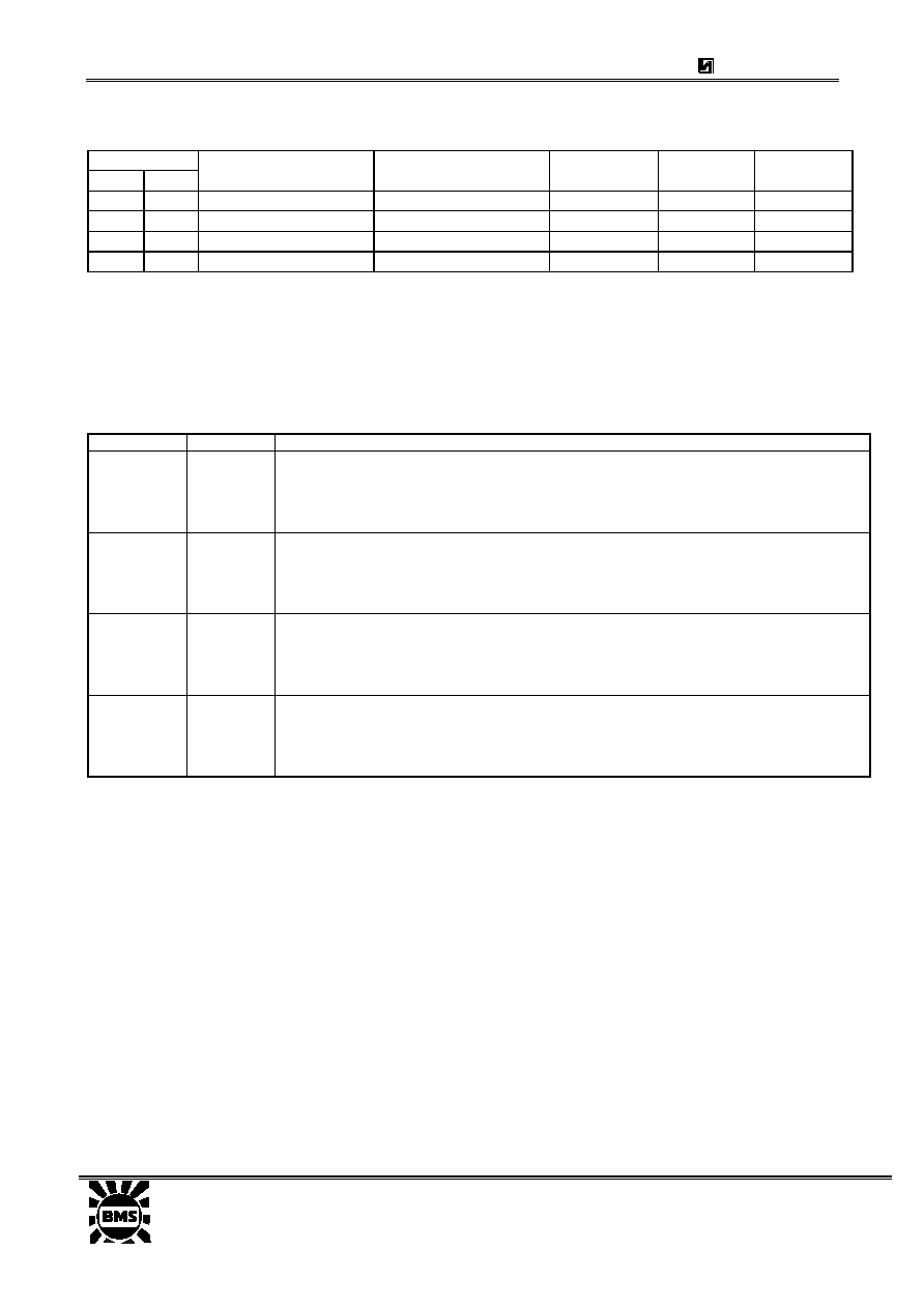
Table 1. Display Mode
Select Input
Alarm Sleep
Display Mode
Digit No.l
Digit No.2
Digit No.3
Digit No.4
NC
NC
Time display
10's hour, AM/PM
Hour
10's minute Minute
Vc,s
NC
Alarm display
10's hour, AM/PM Hour
10's
minute
Minute
NC
Vss
Sleep display
Blanked
Hour
10's minute Minute
V..s
Vss
Seconds
display Blanked
Minute 10's
second
Second
NOTE: If Vss is applied to both input of "alarm display" and "sleep display" simultaneously,
the seconds display mode is entered.
Time setting input:
Two setting inputs for "hours" and "minutes" are provided. The
application of Vgg causes the time setting in Table 2 to occur. An internal
pull-down resistor each is provided.
Table 2. Display Mode
Display Mode Set Input
Functions
Time HOUR
MIN
BOTH
"Hours" are incremented +1 immediately and advance at a 2Hz rate 1/4 to 3/4 second later.
"Minutes" are incremented +1 immediately and advance at a 2Hz rate 1/4 to 3/4 second later.
"Seconds" are reset
Both operations shown above are performed.
Seconds
(Alarm &
Sleep)
HOUR
(Note)
MIN
BOTH
"Seconds" are cleared to [00].
"Hold" mode.
"Hours" and "Minutes" are reset to (0:00) (24hour basis) or (12:00) (12hour basis).
Alarm HOUR
MIN
BOTH
"Hours" are incremented +1 immediately and advance at a 2Hz rate 1/4 to 3/4 second later.
"Minutes" are incremented +1 immediately and advance at a 2Hz rate 1/4 to 3/4 second later.
"Hours" and "Minutes" are reset to [0:00] (24-hour basis) or [12:00] (12-hour basis).
Sleep HOUR
MIN
BOTH
The moment. V
DD
is applied to "sleep display", the sleep counter is set to [0:59].
The moment
VDD
is applied to "sleep display" and "hour set" simultaneously, the sleep counter
is set to (1:59). The sleep counter counts down at a 2Hz rate.
The sleep counter counts down at a 2Hz rate.
Once the reset mode or hold mode is entered, another function input is locked until both "hour set"
input and "minute set" input are released.
Note: When "seconds" display is at 50 to 59, "seconds" are reset to [00] and a carry occurs to
"minutes" +1.
û 12/24-hour select input:
Leaiving this pin unconnected (V
DD
) causes the 12-hour basis to be selected;
connecting this pin to V
SS
causes the 24-hour basis to be selected. An internal pull-
down resistor is provided.
û Power failure indication:
It the power supply voltage drops and is applied again, all the on-segments flash and
the power failure indication mode is entered. The power failure indication mode is
released by applying V
SS
to "hour set" or "minutes set"
û Alarm operation and alarm
output:
When the alarm set time is reached, the alarm signal is delivered. This signal continues
to be delivered for 1 hour 59 minutes unless reset by "alarm off" or "snooze input". This
signal is provided for the tone-signal of 900Hz with 50% duty of 2Hz gated. A simple
LPF can be used to turn this alarm signal into DC signal as required.
û Snooze input:
By momentarily connecting this pin to V
SS
at the alarm on-state, the alarm output is
inhibited for 8 to 9 minutes, after which used repeatedly for 1 hour 59 minutes. An
I N T E G R A L
IL8560
BELMICROSYSTEMS
3
internal pull-down resistor is provided. By connecting "snooze input" to V
SS
at the alarm
off-state, the sleep timer counter is reset to [0:00]. (The sleep timer is reset with one û
touch.)
û Alarm off input:
Connecting this input pin to V
SS
inhibits the alarm output momentarily. An internal
pulldown resistor is provided.
û Sleep timer and sleep output:
The sleep output can be used to keep the radio turned on for any period of time up to
59 minutes or 1 hour 59 minutes. Table 2 shows how to select the period (59 minutes or
1 hour 59 minutes). This sleep timer uses a down counter. When the counter contents
reach [00], the output stops being delivered, turning off the radio. By connecting
"snooze input" to V
SS
at the sleep output on-state, the sleep output is inhibited.
ABSOLUTE MAXIMUM RATINGS (T. = 25
o
C )
Characteristic Symbol
Value
Unit
Maximum Supply Voltage
V
DD
-15 - + 0.3
V
Input Voltage
V
IN
-15 - + 0.3
V
Output Voltage
V
OUT
-15 -+ 0.3
V
Input Clamp Current (50/60Hz Input)
I
IN
-0.4 - + 0.4
mA
Allowable Power Dissipation (T
A
= 70úC)
P
dmax
0.7
W
Operating Temperature
T
A
- 30 - + 70
úC
Storage Temperature
Tstg
- 55 - + 125
úC
ALLOWABLE OPERATING RANGES (T.=25úC, Vss=0V)
Characteristic Symbol
Test
Condition
Min
Typ
Max
Unit
Supply Voltage
V
DD
-14.0 -7.5
V
50/60Hz input
-1.0
Input High Voltage
V
IH
Other inputs
-1.5
V
Input Low Voltage
V
IL
All
inputs
V
DD
+2 V
Input Voltage on 50/60Hz input
V
AC-IN
Referenced to Vgg
VLED
V
ELECTRICAL CHARACTERISTICS (T. = 25úC, V
DD
= -12V; unless otherwise specified)
Characteristic Pins
Symbol
Test
Condition Min
Max
Unit
1 V
IH
=-1,5V, V
IL
=V
DD
+2V,
I
OH
=36mA
-1
5%
16,17 I
OH
=5 mA
-1
5%
High Level Output
Voltage
2-14
V
OH
I
OH
=18 mA, C
L
=150pF
-1
5%
V
1 I
OL
=0,02mA
V
DD
+2
0,2
16,17 I
OL
=0,01mA
V
DD
+2
0,2
Low Level Output Voltage
2-14
V
OL
I
OL
=0,02mA
V
DD
+2
0,2
V
I
IH
10
5%
A
Output Leakage Current 25
I
IL
U
TEST
=12V
-10
5%
A
I
IH
20
5%
A
Output Leakage Current 18,19,21-
24,26,28 I
IL
U
TEST
=12V
-5
5%
A
Supply Current
20
I
DD
U
TEST
=12V
7
5%
mA
I N T E G R A L
IL8560
BELMICROSYSTEMS
4
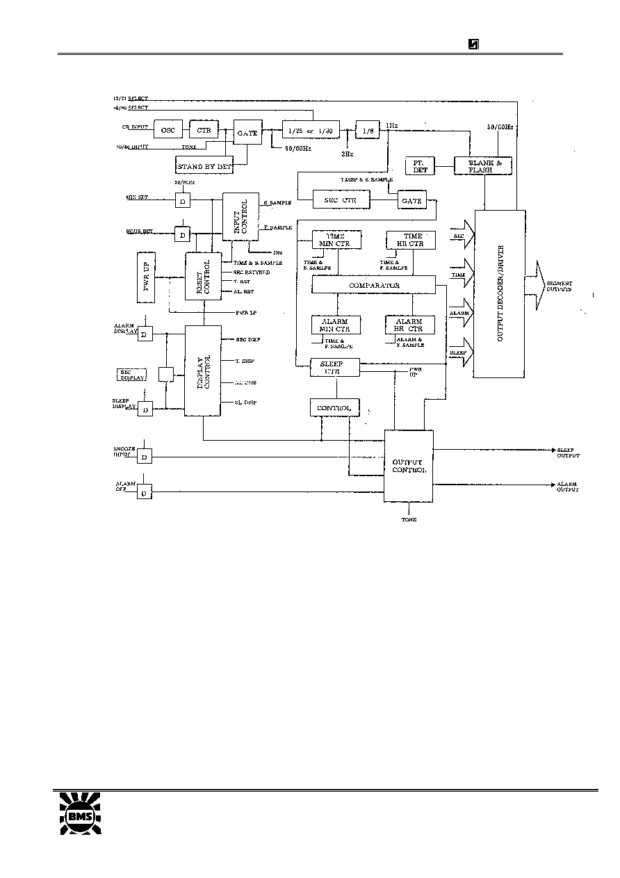
BLOCK DIAGRAM
I N T E G R A L
IL8560
BELMICROSYSTEMS
5
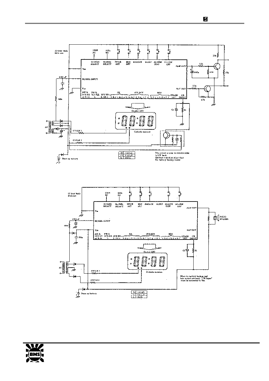
SAMPLE APPLICATION CIRCUIT FOR CLOCK RADIO USE (+ power supply)
SAMPLE APPLICATION CIRCUIT FOR CLOCK USE (-power supply)