
ILC556N
1
G
ENERAL PURPOSE DUAL TIMER
ILC556N is designed to be used: as high-precision pulse oscillator with adjustable frequency
and on-off time ratio; for producing accurate time delays using
external resistors and capacitors; as a timer in domestic
appliances, in measuring equipment, computers; as functional
units in electronic instruments. The timer may be used as
oscillator producing accurate time delays and frequencies.
In astable mode the pulse width of each circuit is controlled by
one external resistor and capacitor. In monostable mode, when
used as oscillator, its own frequency of oscillation and on-off time
ratio are controlled by two external resistors and one capacitor.
Unlike bipolar timer, CONTROL VOLTAGE output does not
require any capacitor decoupling. TRIGGER, RESET inputs are
active as per low level. Output inverter provides sufficient drain
and source currents to control TTL-loads, and provides minimum
bias when controlling CMOS-loads. Input voltage levels are
compatible with standard CMOS levels.
û Output voltage levels are compatible with input levels of CMOS ICs.
û Supply current: not more than 600 A.
û Supply voltage range: from 2.0 to 18V.
û Input current: 50, 100 pA at T=25 ú—.
û Output current: 20 mA.
û Timing from microseconds to hours.
û Operates both in astable and monostable modes.
û Adjustable duty cycle.
û Temperature stability: 0.06%/ú—.
û Latch current not less than 100 mA at T=70 ú—.
û Allowed static potential value: not less than 2000V (HBM) and not less than 200 V (ÃÃ).
1
14
T
A
= -20
ú to 70ú C
Pin Configuration
ILC556N
DISCHARGE1
V
CC
01
02
03
04
05
06
07
08
09
10
11
12
13
14
THRESHOLD1
CONTROL
VOLTAGE1
RESET1
OUTPUT1
TRIGGER1
GND
TRIGGER2
OUTPUT2
RESET2
CONTROL
VOLTAGE2
THRESHOLD2
DISCHARGE2
ILC556N
2
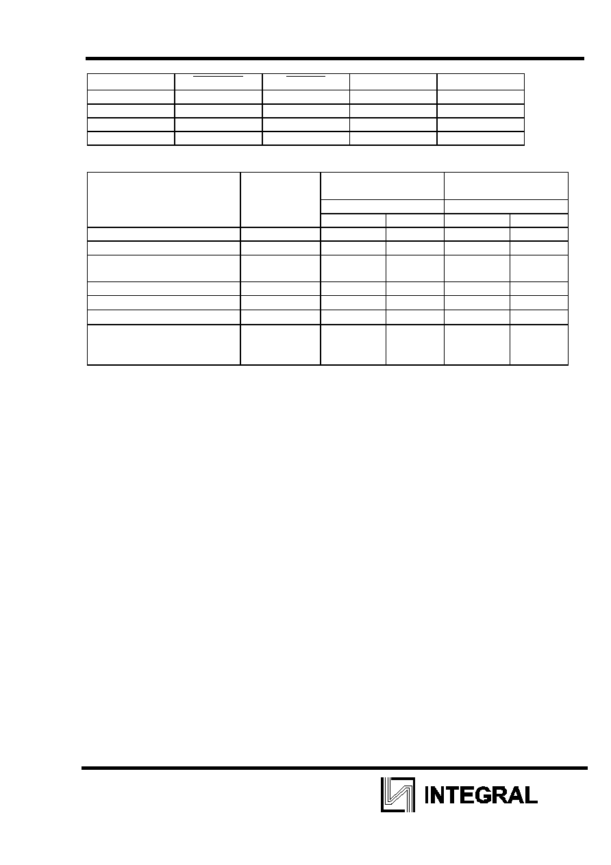
Truth Table
THRESHOLD
TRIGGER
RESET
OUTPUT DISCHARGE
X X L L ON
> 2/3 V
CC
>
1/3 V
CC
H
L
ON
< 2/3 V
CC
>
1/3 V
CC
H STABLE
STABLE
X <
1/3 V
CC
H
H
OFF
Maximum ratings and recommended operating conditions
Parameter, unit
Symbol
Recommended
operating conditions
Maximum ratings
Typical Typical
Min Max Min Max
Supply voltage, V
V
CC
2.0
18.0
0
18.0
Output current, mA
I
O
-
20
-
100
Input voltage, V
V
TH,
V
TRIG,
V
RST
- -
-0.3
V
CC
+0.3
Power dissipation, mW
P
D
- - -
300
Operating temperature,
ú—
T
OPR
-20 70 -20 85
Storage temperature,
ú—
T
STG
- -
-65
150
Lead solder temperature,
ú—
(10 sec max)
T
SOLDER
- - 260
ILC556N
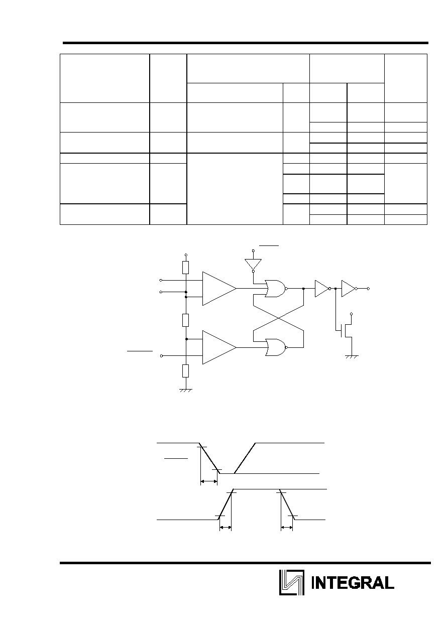
4
DC characteristics
Parameter Symbol Condition
Typical
Tempera
-
ture
R
L
, C
L
V
CC,
V
Min Max ú—
Clock rise
and fall time, ns
t
THL
, t
TLH
R
L
= 10 ÃŒhm, C
L
= 10
pF
5.0 -
75
25
10
-
150
-20,
70
Maximum oscillation
f
MAX
Monostable
mode 2.0-
500
25
10
frequency, kHz
18.0 200
-20, 70
Initial frequency, %
5
Oscillation frequency
f
R
L
= 1 - 100 kŒhm,
5.0
0.02
-20, 70
temperature ratio,
%/ú—
C
L
= 0.1
F
10.0
0.03
15.0
0.06
Oscillation frequency
f
5.0
3
25
10
instability, %/V
6
-20, 70
Block diagram
+
-
+
-
R
R
R
threshold
control
voltage
TRIGGER
ComparatorA
Comparator B
OUTPUT
DISCHARGE
RESET
Vcc
Trigger
Time diagram
t
THL
t
TLH
t
HL
TRIGGER
GND
V
CC
GND
V
CC
OUTPUT
0.9
0.1
0.1
0.9
0.9
0.1
