
ILX232
1
Interface transceiver of RS-232 standard with one supply
voltage
IC ILX232 is purposed for application in high-performance information processing systems and
control devices of wide application.
Input voltage levels are compatible with standard —MOS levels.
û Output voltage levels are compatible with input
levels of C-MOS, N-MOS and TTL integrated
circuits.
û Supply voltage range from 2.0 to 6.0 V.
û Low input current: 1.0 mkA; 0.1 mkA at “ = 25
ú
—.
û Output current 24 mA.
û Latching current not less than 450 mA at “ = 25
ú
—
û
Tolerable value of static potential not less than
2000V
Truth table
Inputs
Outputs
R
IN
, T
IN
R
OVT
, T
OVT
H
L
L
H
Note -
H - voltage high level;
L - low voltage level
IC marking in package
ILX232N Plastic DIP
ILX232D SOIC
“
¿
= from -40 to 85
Ó
—
For all packages
Pin symbols in package
ILX
232
C1+
01
V+
02
03
C2+
04
05
06
07
GND
08
16
15
14
13
12
11
10
09
V
CC
C1-
C2-
T2
OUT
V-
R2
IN
R2
OUT
T2
IN
T1
IN
R1
OUT
R1
IN
T1
OUT

ILX232
2
Table of pin description
Pin No.
Symbol
Pin name
01
C1+
Output of external capacitance of positive voltage multiplier unit
02
V+
Output of positive voltage of multiplier unit
03
C1-
Output of external capacitance of positive voltage multiplier unit
04
C2+
Output of external capacitance of negative voltage multiplier unit
05
C2-
Output of external capacitance of negative voltage multiplier unit
06
V-
Output of negative voltage of multiplier unit
07 T2
OUT
Output of transmitter data (levels RS - 232)
08 R2
IN
Input of receiver data (levels RS - 232)
09 R2
OUT
Output of receiver data (levels TTL/KMOS)
10 T2
IN
Input of transmitter data (levels TTL/KMOS)
11 T1
IN
Input of transmitter data (levels TTL/KMOS)
12 R1
OUT
Output of receiver data (levels TTL/KMOS)
13 R1
IN
Input of receiver data (levels RS - 232)
14 T1
OUT
Output of transmitter data (levels RS - 232)
15 GND
Common
output
16 V
CC
Supply output of voltage source
Maximum conditions
Rate
Symbol Parameter
min max
Unit
V
CC
Supply
voltage
-0.3 6.0
V
V+
Transmitter high output voltage
V
CC
-0.3
14
V-
Transmitter low output voltage
-0.3
-14
V
TIN
Transmitter input voltage
-0.3
V+ +0.3
V
RIN
Receiver input voltage
-30
30
P
D
Dissipated
power
DIP - package
SO - package
-
842
762
mW
I
SC
Output current of transmitter short circuit
-
Continu-
ously
mA
“ý Ambient
temperature
-60 150
Œ
—

ILX232
3
Absolute maximum conditions
Rate
Symbol Parameter
min max
Unit
V
CC
Supply
voltage
4.5 5.5
V
V+
Transmitter output high voltage
5.0
-
V-
Transmitter output low voltage
-5.0
-
V
TIN
Transmitter input voltage
0
V
——
V
RIN
Receiver input voltage
-30
30
I
SC
Transmitter short circuit output current
-
60
mA
“ý Ambient
temperature
-40 85
Œ
—
0.1
F
0.1
F
16
2
6
14
7
13
8
15
9
12
10
11
5
4
3
1
5V
TTL/CMOS
Intput
TTL/CMOS
Output
RS-232
Input
RS-232
Output
5Í
5Í
V+
V-
0.1
F
0.1
F
0.1
F
+
+
C1+
C1-
C2+
C2-
+
+
+
Static parameters
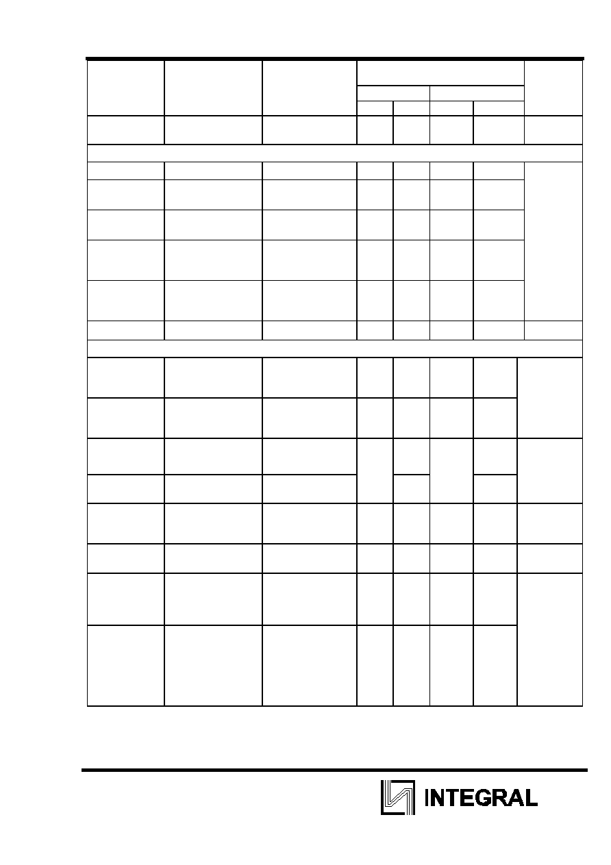
ILX232
4
Rate
25
úC
ÓÚ -40
úC ‰Ó 85 úC
Symbol Parameter
Test
conditions
min max min max
Unit
I
CC
Consumption
current static
V
CC
=5.5 V
V
IL
= 0 V
- 10.0 - 14.0
mA
Receiver electrical parameters
V
h
Hysteresis voltage
V
CC
=5.0 V
0.2
0.9
0.2
1.0
V
V
O
n
On (operation)
voltage
V
O
ò 0.1 V
I
OL
ò 20 mkA
- 2.4 - 2.3
V
off
Off (dropout) voltage V
O
ô V
CC
-0.1 V
I
OH
ò -20 mkA
0.8 - 0.9 -
V
OL
Output low voltage I
OL
= 3.2 Ï¿
V
——
= 4.5 V
V
IH
= 2.4 V
- 0.3 - 0.4
V
OH
Output high voltage I
OH
= -1.0 Ï¿
V
——
= 4.5 V
V
IL
= 0.8 V
3.6 - 3.5 -
R
I
Input resistance
V
——
= 5.0 V
3.0
7.0
3.0
7.0
kOhm
Transmitter electrical parameters
V
OL
Output low voltage V
——
= 4.5 V
V
IH
= 2.0 V
R
L
= 3.0 kOhm
- -5.2 - -5.0
V
V
OH
Output high voltage V
——
= 4.5 V
V
IL
= 0.8 V
R
L
= 3.0 kOhm
5.2 - 5.0 -
I
IL
Input low current
V
——
=5.5 V
V
IL
= 0 V
- -1.0 - -10.0 mkA
I
IH
Input high current
V
——
=5.5 V
V
IH
= V
——
1.0 10.0
SR
Speed of output
front change
V
——
=5.0 V
—
L
=50 - 1000 pF
R
L
= 3.0 - 7.0 kOhm
3.0 30 2.7 27 V/mks
R
Œ
Output resistance
V
——
= V+ = V- = 0 V
V
O
=
2 V
350 - 300 -
Ohm
I
SC
Short circuit output
current
V
——
=5.5 V
V
O
= 0 V
V
I
= V
——
V
I
= 0 V
-50
50
-60
60
mA
ST
Speed of information
transmission
V
——
=4.5 V
—
L
= 1000 pF
R
L
= 3.0 kOhm
t
W
= 7mks (for
extreme -
t
W
=
8mks)
140 - 120 -
kbit/Ò
Dynamic parameters

ILX232
5
Rate
25
úC
from -40
úC
to 85
úC
Symbol Parameter
Test
conditions
min
max
min
max
Unit
t
PHLR
(t
PLHR
)
Signal propagation delay
time when switching on (off)
V
——
= 4.5 V
—
L
= 150 pF
V
IL
= 0 V
V
IH
= 3.0 V
t
LH
=
t
HL
ò 10 ns
-
9.7
-
10
mks
t
PHLT
(t
PLHT
)
Signal propagation delay
time when switching on (off)
V
——
= 4.5 V
—
L
= 2500 pF
V
IL
= 0 V
V
IH
= 3.0 V
R
L
= 3 kOhm
t
LH
=
t
HL
ò 10 ns
5.0
6.0
Capacitance
Symbol Parameter
V
CC
,
V
Rate
Unit
C
IN
Input
capacitance
5.0
9.0
pF
C
PD
Dynamic
capacitance
90
Timing diagram when measuring IC dynamic parameters
+3 V
t
PLHR
t
PHLR
Rin
1.5 V
0 V
V
OL
V
OH
Rout
0.5Vcc
0.5Vcc
1.5 V
Figure 3