IN87C51N
1
CMOS SINGLE-CHIP 8-BIT MICROCONTROLLER
WITH 4K BYTES OF EPROM MEMORY
The 87C51 is the EPROM version of the 80C51. Microcontroller fabricated with high-
density CMOS technology. It contains 4K bytes of on chip Program memory that can be
electrically programmed The 80C51 contains a 4k x 8 ROM , a 128 x 8 RAM , 32 I/O lines,
two 16-bit counter/timers, a five-source, two-priority level nested interrupt structure, a
serial I/O port for either multi-processor communications, I/O expansion or full duplex
UART, and on-chip oscillator and clock circuits.
The device has two software selectable modes of power reduction
idle mode and
power-down mode. The idle mode freezes the CPU while allowing the RAM, timers, serial
port, and interrupt system to continue functioning. The power-down mode saves the RAM
contents but freezes the oscillator, causing all other chip functions to be inoperative.
FEATURES
8031/8051 compatible (MCS-51 family)
4K EPROM
128 x 8 RAM
Two 16-bit counter/timers
Full duplex serial channel
Boolean processor
Memory addressing capability
64k ROM and 64k RAM
Power control modes:
Idle mode
Power-down mode
CMOS and TTL compatible
Two speed ranges at V
CC
=5V
12 MHz
16 MHz
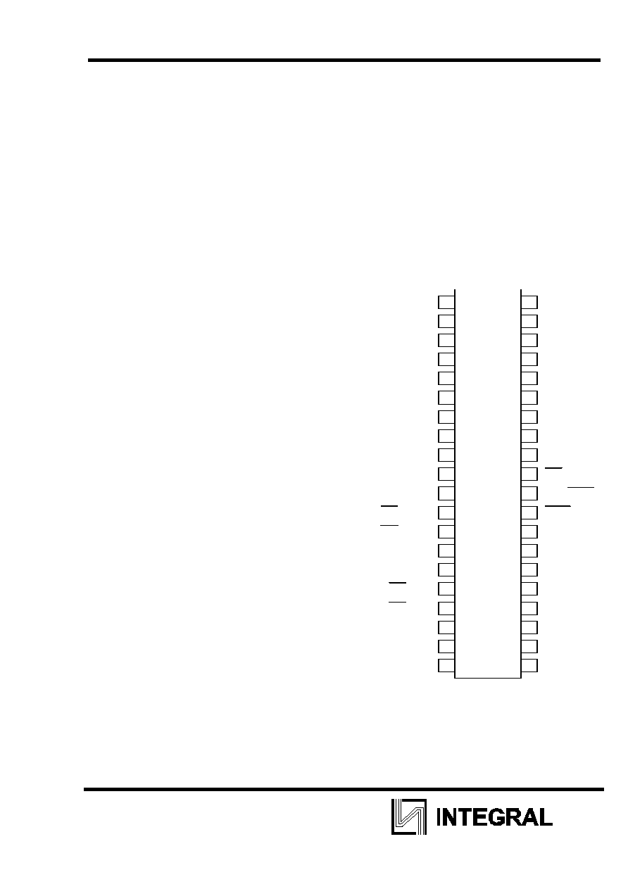
PIN CONFIGURATIONS
P L A S T IC
D U A L
IN - L IN E
P A C K A G E
3 9
1
2
3
4
5
4 0
6
8
1 0
1 1
1 2
1 3
1 4
1 5
1 6
1 7
1 8
1 9
2 0
2 1
2 2
2 3
2 4
2 5
2 6
2 7
2 8
2 9
3 0
3 1
3 2
3 3
3 4
3 5
3 6
3 7
3 8
P 1 .0
P 1 .0
P 1 .2
P 1 .3
P 1 .4
P 1 .5
R x D /P 3 .0
T x D /P 3 .2
P 1 .1
9
7
P 1 .6
P 1 .7
R S T
T 0 /P 3 .4
T 1 /P 3 .5
W R /P 3 6
R D /P 3 .7
X T A L 2
X T A L 1
V s s
V c c
P 0 .0 /A D 0
P 0 .1 /A D 1
P 0 .2 /A D 2
P 0 .3 /A D 3
P 0 .4 /A D 4
P 0 .5 /A D 5
P 0 .6 /A D 6
P 0 .7 /A D 6
E A /V p r
A L E /P P O G
P S E N
P 2 .7 /A 1 5
P 2 .6 /A 1 4
P 2 .5 /A 1 3
P 2 .4 /A 1 2
P 2 .3 /A 1 1
P 2 .2 /A 1 0
P 2 .1 /A 9
P 2 .0 /A 8
I N T 0 /P 3 .2
I N T 1 /P 3 .3
IN87C51N
2
CMOS single-chip 8-bit microcontroller 87C51
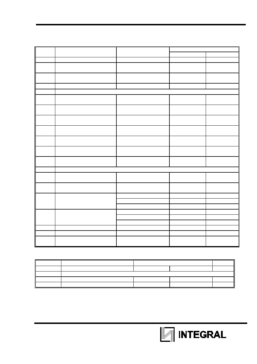
DC ELECTRICAL CHARACTERISTICS FOR INTEGRAL DEVICES
T=-10
o
C to + 70
o
C; Vcc= 5V
10%
Parameter Test
conditions
Limits
Symbol
Min Max
Vcc
4,5
5,5
Icc
Supply current operating, mA
Vcc = 5,5 V
Fclc = 12MHz
- 25
Icc1
Idle mode current, mA
Vcc = 5,5 V
Fclc = 12MHz
- 4,0
Ipd
Pover-down current, mkA
2V
�Vpd�Vcc max
- 50
INPUTS:
Vil
LOW level input voltage, V
(exept EA)
-0,5
0.2Vcc-0,1
Vili
LOW level input voltage, V
(for EA)
0
0.2Vcc-0,3
Vih
HIGH level input voltage, V
(exept XTAL1, RST)
0,2Vcc
+0,9
Vcc+0,5
Vih1
HIGH level input voltage, V
(for XTAL1, RST)
0,7Vcc
Vcc+0,5
-Iil
Input current logic 1, mkA
(Ports 1, 2 and 3)
Vi=0,45 V
-
-50
Itl
Input current logic 1 to 0, mkA
(Ports 1, 2 and 3)
Vi=2 V
-
-650
Ili
Input leacage current, mkA
(Port 0, EA)
0,45V
�Vi�Vcc
- 10
OUTPUTS:
Vol
LOW level output voltage, V
(Ports 1, 2 and 3)
Iol = 1,6 mA
-
0,45
Vol1
LOW level output voltage, V
(Ports 0, ALE, PSEN)
Iol = 3,2 mA
-
0,45
Voh
HIGH level output voltage, V
-Ioh=60 mkA
2,4
-
(Ports 1, 2 and 3)
-Ioh=25 mkA
0,75Vcc
-Ioh=10
mkA
0,9Vcc
Voh1
HIGH level output voltage, V
-Ioh=800 mkA
2,4
-
(Ports 0, ALE, PSEN)
-Ioh=300 mkA
0,75Vcc
-Ioh=80
mkA
0,9Vcc
Rrst
RST pull-down resistor, kOm
50
300
Ci/0
I/O pin capasitance, pF test
frecuency=1MHz -
10
AC ELECTRICAL CHARACTERISTICS FOR INTEGRAL DEVICES
T=-10
o
C to + 70
o
C; Vcc= 5V
10%
Symbol Parameter
Variable
Oscillator
Unit
Fclc
Min
Max
Oscillator
Frequency:
IN87C51N - 12
3,5
12
MHz
IN87C51N - 16
3,5
16
MHz