
IZ8016
1
3.5
D
IGIT
T
HERMOMETER
DESCRIPTION
The IZ8016 is a CMOS circuit provided with digital thermometer function. Temperature reading
from -50
o
C to +50
o
C is detected
by use of a thermistor as a sensor and temperature is displayed on a LCD by 0.2
o
C step. High
accuracy is obtained in wide range of
-50
o
C ~ +50
o
C by providing non-linear correction circuit on the chip.
FEATURES
� Measurement accuracy: 1
o
C
� Resolution : 0.2
o
C (
o
F)
� 3
1
/
2
+ 7 Indicators, 3
1
/
2
duty LCD
� Low power consumption
� Few external components
� Easiness in adjustment
� Single 1.5V battery operation
� Package Type: Bare chip
FUNCTIONS
� Measurable temperature range -49
o
C ~
+49.8
o
C
-57
o
F ~ +121.8
o
F
� Suitable Thermistor RT=10K 1% (at
25
o
C)
� Sampling Cycle 1 seconds, 3 seconds, 5
seconds,
10 seconds (Default 10 sec)
� Oscillation Frequency 32.768 kHz
� Temperature adjustment: Adjustment of
temperature is
made by adjusting fundamental resistance
against
dispersion in resistance values of
thermistors
ABSOLUTE MAXIMUM RATINGS
Characteristic Symbol
Value Unit
Supply Voltage (V
CC
) V
CC
- 0.1 ~ + 3.0
V
Operating Temperature Range
T
opr
- 50 ~ + 50
o
C
Storage Temperature Range
T
stg
- 50 ~ + 125
o
C
ELECTRICAL CHARACTERISTICS
(Ta = 25
o
C, V
SS
= 0V, V
CC
= 1.5V unless otherwise specified)
Characteristic
Symbo
l
Test Condition
Min
Typ
Max
Unit
Operating Voltage
V
CC
1.20
1.50
2.00
V
LCD Voltage
V
DD
3.00
V
Supply Current
I
CC
Operating
50
80
A
I
STD
Standby 5
10
A
IZ8016
2
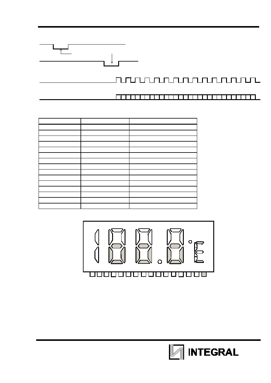
SERIAL OUTPUT
INT (TO CPU)
PUR
BT8016 measure the temperature once
(FROM CPU)
FINISH
SHCK (FROM CPU)
MD
1
2
3
4
5
6
7
8
9
10
11
12
13
14
15
Temperature data converted serially by MD, SHCK INT, PUR terminals.
Temperature data is output a total 15-bits data.
Bit No.
Function
Remark
01
Polarity
Polarity (1= Minus; 0 = Plus)
02
(Hundred digit) (
o
C no use)
03 80
04 40
05 20
06 10
07 8
08 4
09 2
10 1
11 0.8
12 0.4
13 0.2
14 0.1
15 (
o
C/
o
F) (0
=
o
C; 1 =
o
F)
LCD FORMAT
B
1
C
1
A
2
F
2
B
2
G
2
D
2
E
2
C
2
F
3
E
3
B
3
C
3
A
3
G
3
D
3
D
4
G
4
E
4
C
4
F
4
B
4
A
4
Dp
CF
CF
F
C
CO
M
1
CO
M
2
D2
/
B
C1
E2/
F
2
G2
/
A
2
C2
/
B
2
G3
/
A
3
E3/
F
3
D3
/
D
p
E4/
F
4
G4
/
A
4
C4
/
B
4
-/
C
F
F/
C
C3
/
B
3
D4
/
-
1
2
3
4
5
6
7
8
9
10
11
12
13
14
15
16

IZ8016
4
PAD DIAGRAM
PAD DIAGRAM IZ 8016
Chip size: 2800 x 2300
Pad size : 100 x 100
Unit : mm
36
35
34
33
32
31
30
29
28
27
26
25
24
23
22
21
20
19
18
17
16
15
14
13
12
11
10
9
8
7
6
5
4
3
2
1
X
Y
(0,0)
NOTE: Substrate is connected to V
SS
PAD ASSIGNMENT
Pad
No.
Signal Description X
Y
Pad
No.
Signa
l
Description X
Y
1
OSC2
Oscillator circuit
969
1014
19
SEG1
0
LCD segment drive
-923
-1016
2 PUR
713 1014 20 SEG9
LCD
segment drive
-763
-1016
3
S1
Pin option, select the
thermistor sampling cycle
(default 10 seconds)
314 1014 21 SEG8
LCD
segment drive
-434
-1016
4 S2
80 1014 22 SEG7
LCD
segment drive
-269
-1016
S1 S2 SAMPLING
CYCLE, sec
V
SS
V
SS
10
V
SS
V
CC
1
V
CC
V
SS
2
V
CC
V
CC
5
5
CAP1
Booster capacitor
-148
1014
23
SEG6 LCD segment drive
59
-1016
6 T1
Test
input
-318 1014 24 SEG5 LCD segment drive
224
-1016
7 T2
Test
input
-517 1014 25 SEG4 LCD segment drive
552
-1016
8
ADJ
Adjust the fixed
temperature (active high)
-714 1014 26 SEG3 LCD
segment drive
718
-1016
9
REF
Terminal for temperature
detection
-876 1014 27 SEG2 LCD
segment drive
1046
-1016
10
THER
Terminal for temperature
detection
-1244 1014 28 SEG1 LCD
segment drive
1229
-1016
11
CAP
Terminal for temperature
detection
-1266 685 29 COM
1
LCD common drive
1261
-723
12 V
CC
Supply
voltage
-1266
525
30
V
DD
LCD supply voltage
1261
-295
13
CAP2
Booster capacitor
-1266
223
31
V
SS
GND
1261 -127
14
COM2
LCD common drive
-1266
-213
32
CF
o
C/
o
F Terminal, default
(V
SS
) select
o
C
1261 40
15
SEG14
LCD segment drive
-1266
-383
33
INT
Signal to interrupt the
MPU
1261 218
16
SEG13
LCD segment drive
-1266
-646
34
MD
Serial Data
1261
431
17
SEG12
LCD segment drive
-1266
-808
35
SHC
K
Serial shift Clock Input
1261
606
18
SEG11
LCD segment drive
-1266 -1016
36
OSC1 Oscillator circuit
1261
772
