 | –≠–ª–µ–∫—Ç—Ä–æ–Ω–Ω—ã–π –∫–æ–º–ø–æ–Ω–µ–Ω—Ç: 31244 | –°–∫–∞—á–∞—Ç—å:  PDF PDF  ZIP ZIP |

Intel
Æ
31244 PCI-X to Serial ATA
Controller
Datasheet
Product Features
Warning:
Intel Corporation products are not intended for use in life support appliances,
devices or systems. Use of a Intel products in such applications without written
consent is prohibited.
I
Four SATA Channels at 1.5 Gb/s
I
Serial ATA: High speed Serialized AT
Attachment Specification, Revision
1.0e Compliant
I
64-bit/133 MHz PCI-X Bus. Backwards
compatible to 32-bit/33 MHz and
64-bit/66 MHz
I
Compatible with Existing Operating
Systems
I
Supports Native PCI IDE
I
Hot-Plug Drives
I
Supports Master/Slave Mode for
Compatibility with Existing Operating
Systems
I
Supports SATA Direct Port Access
(Master/Master Mode)
I
Independent DMA Masters for Each
SATA Channel
I
3.3 V and 2.5 V Supply, 2.0 W
Maximum
Document Number: 273595-004
April 28, 2003

Intel
Æ
31244 PCI-X to Serial ATA Controller
2
April 28, 2003
Datasheet
INFORMATION IN THIS DOCUMENT IS PROVIDED IN CONNECTION WITH INTELÆ PRODUCTS. NO LICENSE, EXPRESS OR IMPLIED, BY
ESTOPPEL OR OTHERWISE, TO ANY INTELLECTUAL PROPERTY RIGHTS IS GRANTED BY THIS DOCUMENT. EXCEPT AS PROVIDED IN
INTEL'S TERMS AND CONDITIONS OF SALE FOR SUCH PRODUCTS, INTEL ASSUMES NO LIABILITY WHATSOEVER, AND INTEL DISCLAIMS
ANY EXPRESS OR IMPLIED WARRANTY, RELATING TO SALE AND/OR USE OF INTEL PRODUCTS INCLUDING LIABILITY OR WARRANTIES
RELATING TO FITNESS FOR A PARTICULAR PURPOSE, MERCHANTABILITY, OR INFRINGEMENT OF ANY PATENT, COPYRIGHT OR OTHER
INTELLECTUAL PROPERTY RIGHT.
Intel products are not intended for use in medical, life saving, life sustaining applications.
Intel may make changes to specifications and product descriptions at any time, without notice.
The IntelÆ 31244 may contain design defects or errors known as errata which may cause the product to deviate from published specifications. Current
characterized errata are available on request.
Intel
Æ
internal code names are subject to change.
Contact your local Intel sales office or your distributor to obtain the latest specifications and before placing your product order.
Copies of documents which have an ordering number and are referenced in this document, or other Intel literature may be obtained by calling
1-800-548-4725 or by visiting Intel's website at http://www.intel.com.
Copyright© Intel Corporation, 2003
AlertVIEW, i960, AnyPoint, AppChoice, BoardWatch, BunnyPeople, CablePort, Celeron, Chips, Commerce Cart, CT Connect, CT Media, Dialogic,
DM3, EtherExpress, ETOX, FlashFile, GatherRound, i386, i486, iCat, iCOMP, Insight960, InstantIP, Intel, Intel logo, Intel386, Intel486, Intel740,
IntelDX2, IntelDX4, IntelSX2, Intel ChatPad, Intel Create&Share, Intel Dot.Station, Intel GigaBlade, Intel InBusiness, Intel Inside, Intel Inside logo, Intel
NetBurst, Intel NetStructure, Intel Play, Intel Play logo, Intel Pocket Concert, Intel SingleDriver, Intel SpeedStep, Intel StrataFlash, Intel TeamStation,
Intel WebOutfitter, Intel Xeon, Intel XScale, Itanium, JobAnalyst, LANDesk, LanRover, MCS, MMX, MMX logo, NetPort, NetportExpress, Optimizer
logo, OverDrive, Paragon, PC Dads, PC Parents, Pentium, Pentium II Xeon, Pentium III Xeon, Performance at Your Command, ProShare,
RemoteExpress, Screamline, Shiva, SmartDie, Solutions960, Sound Mark, StorageExpress, The Computer Inside, The Journey Inside, This Way In,
TokenExpress, Trillium, Vivonic, and VTune are trademarks or registered trademarks of Intel Corporation or its subsidiaries in the United States and
other countries.
*
Other names and brands may be claimed as the property of others.

Intel
Æ
31244 PCI-X to Serial ATA Controller
Datasheet
April 28, 2003
3
Contents
1.0
General Description............................................................................................................ 7
1.1
References ............................................................................................................ 7
2.0
Overview ............................................................................................................................ 8
2.1
Applications ........................................................................................................... 9
2.2
PCI-X Interface.................................................................................................... 10
2.3
Serial ATA Interface ............................................................................................ 11
2.3.1
Direct Port Access (DPA) ....................................................................... 11
2.3.2
Extended Voltage Range ....................................................................... 12
2.3.3
Activity LEDs .......................................................................................... 12
2.4
Serial ROM Interface........................................................................................... 13
2.4.1
JTAG Interface ....................................................................................... 13
3.0
Package Information ........................................................................................................ 14
3.1
Package Introduction........................................................................................... 14
3.1.1
Signal Pin Descriptions .......................................................................... 14
3.1.2
Serial ROM Interface Pin Descriptions................................................... 15
3.1.3
Reference Clock Generation .................................................................. 15
3.1.4
VA0, VA1 (V
CCPLL
) Pin Requirements ................................................... 20
3.1.5
Package/Marking Information................................................................. 21
3.1.6
Intel
Æ
31244 PCI-X to Serial ATA Controller Pinout ...............................23
3.2
Package Thermal Specifications ......................................................................... 30
3.3
Thermal Considerations ...................................................................................... 30
4.0
Electrical Specifications.................................................................................................... 31
4.1
Absolute Maximum Ratings................................................................................. 31
4.2
Recommended Operating Conditions ................................................................. 31
4.3
V
CC5REF
Pin Requirements ................................................................................. 32
4.4
V18x Pin Requirements....................................................................................... 32
4.5
VAx Pin Requirements ........................................................................................ 32
4.6
Targeted DC Specifications................................................................................. 33
4.7
Targeted AC Specifications................................................................................. 34
4.7.1
Clock Signal Timings.............................................................................. 34
4.7.2
PCI Interface Signal Timings.................................................................. 35

Intel
Æ
31244 PCI-X to Serial ATA Controller
4
April 28, 2003
Datasheet
Figures
1
Block Diagram....................................................................................................... 8
2
Quad-Serial ATA Host Bus Adapter...................................................................... 9
3
SATA Unit Register Mapping in Direct Port Access Mode .................................. 11
4
Package Information: 256-pin PBGA .................................................................. 21
5
Dimension Symbols ............................................................................................ 22
6
Intel
Æ
31244 PCI-X to Serial ATA Controller Pinout ............................................ 23
7
17 mm PBGA Package Cross Section ................................................................ 30
8
Output Timing Measurement Waveforms ........................................................... 36
9
Input Timing Measurement Waveforms .............................................................. 36
10
PCI/X TOV(max) Rising Edge AC Test Load...................................................... 36
11
PCI/X TOV(max) Falling Edge AC Test Load ..................................................... 37
12
PCI/X TOV(min) AC Test Load ........................................................................... 37
Tables
1
Normal Mode (Extended Voltage Range Bit = 0) ................................................ 12
2
Extended Voltage Range (Bit = 1)....................................................................... 12
3
Pin Description Nomenclature............................................................................. 14
4
Serial ATA Signals Pin Descriptions ................................................................... 15
5
Serial ROM Interface Pin Descriptions................................................................ 15
6
PCI-X Bus Pin Descriptions ................................................................................ 17
8
JTAG Pin Descriptions ........................................................................................ 19
7
Configuration Pin Descriptions............................................................................ 19
9
Power Supply Pin Descriptions ........................................................................... 20
10
Package Dimensions .......................................................................................... 22
11
256-Lead PBGA Package -- Signal Name Order............................................... 24
12
256-Lead PBGA Package -- Ballpad Number Order ......................................... 27
13
Thermal Characteristics ...................................................................................... 30
14
Absolute Maximum Ratings ................................................................................ 31
15
Recommended Operating Conditions ................................................................. 31
16
DC Characteristics .............................................................................................. 33
17
AC Characteristics .............................................................................................. 34
18
Clock Timings...................................................................................................... 34
19
PCI Signal Timings.............................................................................................. 35

Intel
Æ
31244 PCI-X to Serial ATA Controller
Datasheet
April 28, 2003
5
Revision History
Date
Revision #
Description
April 2003
004
Corrected Figure 4.
February 2003
003
Added package dimensions to Section 3.5.1.
November 2002
002
Revised content of Section 2.4, "Serial ROM Interface."
Added Section 3.1.2, "Serial ROM Interface Pin Descriptions."
Replaced Figure 5, "Intel
Æ
31244 PCI-X to Serial ATA Controller Pinout."
In Table 10, "256-Lead PBGA Package -- Signal Name Order", replaced LED2
with LED2/SCLK (for Ball C1); replaced LED3 with LED3/SDO (for Ball A3);
replaced RFU with SCS# (for Ball C2); replaced RFU with SDI (for Ball E6).
In Table 11, "256-Lead PBGA Package -- Ballpad Number Order", replaced
LED2 with LED2/SCLK (for Ball C1); replaced LED3 with LED3/SDO (for Ball
A3); replaced RFU with SCS# (for Ball C2); replaced RFU with SDI (for Ball E6).
October 2002
001
Initial release.

Intel
Æ
31244 PCI-X to Serial ATA Controller
6
April 28, 2003
Datasheet
This Page Intentionally Left Blank

Intel
Æ
31244 PCI-X to Serial ATA Controller
General Description
Datasheet
April 28, 2003
7
1.0
General Description
The Intel
Æ
31244 PCI-X to serial ATA controller (GD31244) is a state-of-the-art, PCI-X-to-Serial
ATA Controller with four Serial ATA ports running at 1.5 Gb/s. The device is targeted at embedded
applications such as PC motherboards, as well as standalone PCI-X Host Bus Adapter cards and
RAID controllers.
The GD31244 is both a PCI-X Bus Master and Slave, which automatically switches modes as
required.
As a PCI-X Slave, the device supports:
As a PCI-X Bus Master, this device supports:
This device is compliant with the PCI-X bus operating at up to 64 bits at 133 MHz, resulting in burst
data rates of 1064 MBps. The Intel
Æ
31244 PCI-X to serial ATA controller provides four Serial ATA
ports running at 1.5 Gb/s transfer rate, which are compliant to the Serial ATA: High speed Serialized
AT Attachment Specification, Revision 1.0e. The GD31244 derives its Serial ATA clocks from an
internal PLL, with a reference clock of 37.5 MHz provided externally or from a crystal.
The GD31244 is fully compatible with parallel ATA operating system drivers and software. The chip
can be configured in compatibility mode, mapping the PCI-X configuration space to match the x86
standard Primary and Secondary IDE ports. To support both on-board parallel IDE, plus the four
Serial ATA ports, the chip can be configured for native PCI-X mode, allowing Plug-and-Play BIOS
and operating systems to map the Serial ATA drives to non-conflicting task file and I/O address space.
For higher performance in systems where compatibility is not required, all four channels can
be configured as Direct Port Access (DPA).
1.1
References
For more details regarding Serial ATA and PCI, the reader is referred to:
∑
PCI Local Bus Specification, Revision 2.2
∑
PCI-X Addendum to the PCI Local Bus Specification, Revision 1.0a
∑
Serial ATA: High speed Serialized AT Attachment Specification, Revision 1.0e
∑
AT Attachment with Packet Interface - 5 (ATA/ATAPI-5), T13/1321D, Revision 3
∑
I/O Reads
∑
Configuration Read
∑
I/O Writes
∑
Configuration Write
∑
Memory Read Bus Cycles
∑
Single Memory Reads
∑
Line Memory Reads
∑
Multiple Memory Reads
∑
Memory Writes

Intel
Æ
31244 PCI-X to Serial ATA Controller
Overview
8
April 28, 2003
Datasheet
2.0
Overview
The Intel
Æ
31244 PCI-X to serial ATA controller is a single-chip solution for a PCI-X-to-Serial
ATA Host Bus Adapter (HBA). It accepts host commands through the PCI-X bus, processes them
and transmits them to one of four Serial ATA targets. The Intel
Æ
31244 PCI-X to serial ATA
controller supports Serial ATA speeds of 1.5 Gb/s of 8b/10b encoded data, which is equivalent to
150 MB/s of raw data. On the 64-bit PCI-X bus, when run at the maximum frequency of 133 MHz,
the Intel
Æ
31244 PCI-X to serial ATA controller supports a maximum burst transfer rate of
1064 MB/s.
The Intel
Æ
31244 PCI-X to serial ATA controller may be used to build standalone PCI-X HBA
cards (
Figure 1
) to interface Serial ATA Disk Drives, CD-ROMs, DVD ROMs or Tape drives. The
Intel
Æ
31244 PCI-X to serial ATA controller is completely software compatible with all existing
operating systems which support ATA interfaces:
In PC systems, the Intel
Æ
31244 PCI-X to serial ATA controller can also be configured to provide
additional storage capacity to systems already supporting four ATA targets. In non-PC systems, the
Intel
Æ
31244 PCI-X to serial ATA controller may be used as a generic storage controller in servers,
RAID subsystems and Network Attached Storage (NAS) systems. The ease-of-use, flexibility,
performance and low cost of the Intel
Æ
31244 PCI-X to serial ATA controller make it an ideal
choice for all of these applications.
∑
Windows
∑
Linux
∑
Unix
∑
Windows NT
∑
Solaris
∑
Other
Figure 1.
Block Diagram
A9194-03
Dual
Port
FIFO
and
I/O
Transport
Engine
PCI-X
64-bit
133 MHz
Interface
Serializer
00B
Deserializer
Serializer
Serializer
Deserializer
Deserializer
Serializer
Deserializer
TX0P
TX0N
RX0N
RX0P
00B
TX1P
TX1N
LED0
P_AD(63:0)
LED1
LED2
LED3
RX1N
RX1P
00B
TX2P
TX2N
RX2N
RX2P
00B
TX3P
TX3N
RX3N
RX3P
P_CBE(7:0)
P_PAR
P_PAR64
P_FRAME#
P_TRDY#
P_REQ64#
P_IRDY#
P_ACK64#
P_GNT#
P_CLK
P_RST#
P_REQ#
P_STOP#
P_DEVSEL#
P_SERR#
P_PERR#
P_INTA#
Serial ATA
Transport/Link
Layer
PHY
I/F
Serial ATA
Transport/Link
Layer
PHY
I/F
Serial ATA
Transport/Link
Layer
PHY
I/F
Serial ATA
Transport/Link
Layer
PHY
I/F

Intel
Æ
31244 PCI-X to Serial ATA Controller
Overview
Datasheet
April 28, 2003
9
2.1
Applications
The Intel
Æ
31244 PCI-X to serial ATA controller can be used to build a Serial ATA Host Bus
Adapter which connects to the PCI-X bus. Control for external activity LEDs, a 37.5 MHz Crystal,
a voltage regulator and some external resistors and capacitors are needed.
Figure 2.
Quad-Serial ATA Host Bus Adapter
B0418-02
Intel
Æ
31244
PCI-X
to
Serial
ATA
Controller
PCI-X Bus
JTAG
P_AD[63:0]
VIO
VCC
2.5V
3.3V
P_CBE[7:0]
P_PAR
P_PAR64
P_FRAME#
CAP0
CAP1
VA1
P_TRDY#
P_REQ64#
P_IRDY#
P_ACK64#
P_GNT#
P_CLK
P_RST#
P_IDSEL
P_REQ#
P_STOP#
P_DEVSEL#
P_SERR#
P_PERR#
V
CC5REF
P_INTA#
TDI
TD0
TMS
TCK
TRST#
CLKIN
CLKOUT
RBIAS
V18A
V18B
Serial
ATA
Port 0
Connector
Oscillator
Regulator
37.5 MHz
0.1 µF
10 µF
1000
, 1%
CAP2
CAP3
0.1 µF
0.015 µF
2.5V
2.5V
0.01 µF
0.01 µF
18 pF
18 pF
0.1 µF
10 µF
0.01 µF
0.01 µF
Serial
ATA
Port 1
Connector
0.01 µF
0.01 µF
0.01 µF
0.01 µF
Serial
ATA
Port 2
Connector
0.01 µF
0.01 µF
0.01 µF
0.01 µF
Serial
ATA
Port 3
Connector
0.01 µF
0.01 µF
0.01 µF
0.01 µF
RX0P
RX0N
TX0P
TX0N
RX1P
RX1N
TX1P
TX1N
RX2P
RX2N
TX2P
TX2N
RX3P
RX3N
TX3P
TX3N
LED0
LED1
LED2
LED3
VA0
.1µF,
0603,
x7R
.1µF,
0603,
x7R
22µF,
TANT,
EIA-A,
6.3V
22µF,
TANT,
EIA-A,
6.3V
20
0603, 1%
10 µH
10 µH
.1µF,
0603,
x7R
.1µF,
0603,
x7R
22µF,
TANT,
EIA-A,
6.3V
+
+
+
+
22µF,
TANT,
EIA-A,
6.3V
20
0603, 1%
+
+

Intel
Æ
31244 PCI-X to Serial ATA Controller
Overview
10
April 28, 2003
Datasheet
2.2
PCI-X Interface
The 64-bit, 133 MHz PCI-X interface is fully compliant with the PCI Local Bus Specification,
Revision 2.2 and the PCI-X Addendum to the PCI Local Bus Specification, Revision 1.0a. The
PCI-X bus supports up to 1064 MB/s transfer rate of burst data. The Intel
Æ
31244 PCI-X to serial
ATA controller is backwards compatible with 32-bit/33 MHz, 32-bit/66 MHz and 64-bit/66 MHz
operation. The PCI logic supports Plug-n-Play operation, which allows hardware and firmware to
resolve all setup conflicts for the user. The Intel
Æ
31244 PCI-X to serial ATA controller supports
both slave and master data transfers. The devices responds to the following bus cycles as a slave:
As a master, the Intel
Æ
31244 PCI-X to serial ATA controller responds to:
During system initialization, the Configuration Manager of the host system reads the configuration
space of each PCI-X device. After hardware reset, the Intel
Æ
31244 PCI-X to serial ATA controller
only responds to PCI-X Configuration cycles in anticipation of being initialized by the
Configuration Manager. Each PCI-X device is addressable individually by the use of unique
IDSEL signals which, when asserted, indicate that a configuration read or write is occurring to this
device. The Configuration Manager reads the setup registers of each device on the PCI-X bus and
then, based on this information, assigns system resources to each supported function through
Type 0 configuration reads and writes. Type 1 configuration cycles are ignored. This scheme
allows the Intel
Æ
31244 PCI-X to serial ATA controller and its external activity LEDs to be
relocated in the memory and I/O space. Interrupts, DMA Channels and other system resources can
be reallocated appropriately.
∑
I/O Reads
∑
Configuration Read
∑
I/O Writes
∑
Configuration Write
∑
Memory Read Bus Cycles
∑
Single Memory Reads
∑
Line Memory Reads
∑
Multiple Memory Reads
∑
Memory Writes

Intel
Æ
31244 PCI-X to Serial ATA Controller
Overview
Datasheet
April 28, 2003
11
2.3
Serial ATA Interface
Four 1.5 Gb/s Serial ATA ports are located on the Intel
Æ
31244 PCI-X to serial ATA controller, to
support point-to-point connectivity to disk drives, CD ROMs, DVD ROMs or any other Serial ATA
target device. Each port is compliant with the "Serial ATA: High speed Serialized AT Attachment
Specification, Revision 1.0e. High speed differential duplex serial lines send 8B/10B encoded data
to and from the Intel
Æ
31244 PCI-X to serial ATA controller and the target at a maximum raw data
rate of 1.2 Gb/s (150 MB/s). Copies of the targets' Task File Registers are maintained on the Intel
Æ
31244 PCI-X to serial ATA controller and transferred as needed to the target. The Serial ATA
protocol is software compatible with all existing operating systems that support ATA devices,
however, performance and reliability are improved since all data is CRC checked.
2.3.1
Direct Port Access (DPA)
The SATA Direct Port Access architecture allows for independent control of the SATA devices.
Unlike ATA master/slave configuration where only one drive can operate at a time, DPA allows
multiple drivers to be accessed concurrently. In addition, each port supports its own DMA channel
allowing each port to transfer data independently (between a device and memory).
The DPA mode does change the register layout from PCI IDE. Therefore, legacy device drivers do
not support this mode. DPA requires the registers (including the Command Block, Control Block,
DMA, and SATA superset) for each drive to be available at all times. Instead of using I/O space, these
registers are mapped to a single 4 KB memory mapped block. Each port has 512 Bytes; the remaining
2 KB are for the common port registers. The 4 KB block is mapped using one PCI BAR register.
Figure 3.
SATA Unit Register Mapping in Direct Port Access Mode
SATA Port 0 Registers
0
200H
3FCH
400H
5FCH
600H
7FCH
800H
SATA Port 3 Registers
9FCH
SATA Port 1 Registers
Offset
SATA Port 2 Registers
Common Port Registers
1FCH
2 KBytes
512 Bytes
(4 x 512 Bytes)
PCI Configuration Space
10H
14H
Offset
Base Address Register
Upper Base Address Register 0
31
000H
A00H
FFCH
Reserved
1536 Bytes

Intel
Æ
31244 PCI-X to Serial ATA Controller
Overview
12
April 28, 2003
Datasheet
2.3.2
Extended Voltage Range
The SATA voltages were designed primarily for a cable connection to the hard drives. In certain
applications, such as NAS/SAN enclosures, the hard disk drives (HDD) are connected to a backplane,
not a cable (typically in desktop systems). Due to the frequency of the SATA interface, the backplane
creates a significant attenuation of the SATA signals. In an effort to simplify system designs, the
Intel
Æ
31244 PCI-X to serial ATA controller offers an extended voltage range to help alleviate the
issue. This extended voltage range allows standard SATA HDD to be used with SATA backplanes.
Each SATA transmit channel of the Intel
Æ
31244 PCI-X to serial ATA controller can be
independently placed into the External Voltage Mode by setting the Extended Voltage Range bit
(Bit 14) in the appropriate PHY Feature Register to 1. This causes the SATA transmit channel of
the Intel
Æ
31244 PCI-X to serial ATA controller to operate with this extended voltage range. More
information on designing SATA backplanes is available in the Intel
Æ
31244 PCI-X to Serial ATA
Controller Design Guide.
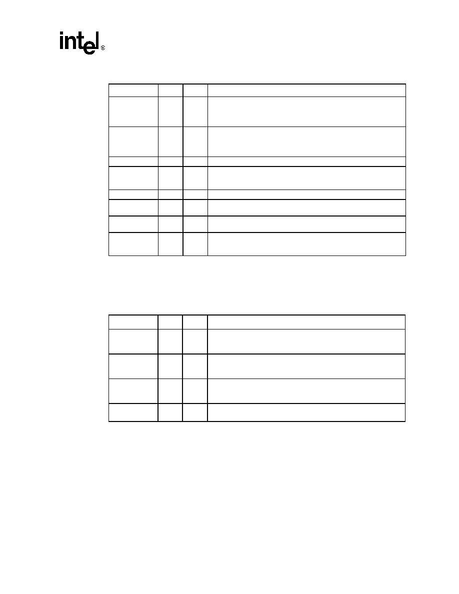
2.3.3
Activity LEDs
Serial ATA interfaces on disk drives, do not include the traditional ATA output, which drives an
LED to indicate that the drive is active. The GD31244 compensates for this missing function by
adding four LED out-puts. In Master/Slave compatibility mode, LED0 goes LOW to turn on an
Activity LED, anytime there is activity on either Channel 0 or Channel 1. Likewise, LED1 goes
LOW to turn on an Activity LED, anytime there is activity on either Channel 2 or Channel 3. These
two outputs may be wire-ORd together to use one LED for all four ports.
When GD31244 is configured in Direct Port Access mode (DPA_MODE# is LOW), then each port
is assigned its own LED as follows:
∑
Port 0 on LED0
∑
Port 1 on LED1
∑
Port 2 on LED2
∑
Port 3 on LED3
Table 1.
Normal Mode (Extended Voltage Range Bit = 0)
Parameter
Description
Minimum
Maximum
Units
V
OUT
TXx output differential peak-to-peak voltage swing
400
600
mVp-p
V
IN
RXx input differential peak-to-peak voltage swing
325
600
mVp-p
Table 2.
Extended Voltage Range (Bit = 1)
Parameter
Description
Minimum
Maximum
Units
V
OUT
TXx output differential peak-to-peak voltage swing
800
1200
mVp-p
V
IN
RXx input differential peak-to-peak voltage swing
175
1200
mVp-p

Intel
Æ
31244 PCI-X to Serial ATA Controller
Overview
Datasheet
April 28, 2003
13
2.4
Serial ROM Interface
In add-in card applications, firmware may be downloaded to the system from a Serial EEPROM or
Serial Flash ROM, via the Serial ROM Interface. This industry standard, 4-pin interface, allows any
size of device, up to 128 KB, to be connected to the Intel
Æ
31244 PCI-X to serial ATA controller. This
SPI interface was designed for compatibility with an ST Microelectronics* M25P10-A or Atmel*
AT25F1024 device.
Two of the pins are dual purpose to support four LED port activity indicators. This four pin
interface is defined as follows:
1. SDI INPUT: Connects to the serial data output (SO) of the Serial EEPROM. Data is shifted out
of the EEPROM on the falling edge of SCLK. Customers are recommended to add pads for
both a pull-up and a pull-down resistor for possible use in the future.
2. SDO OUTPUT: Connects to the serial data input (SI) of the Serial EEPROM. Data is latched
into the Serial EEPROM on the rising edge of SCLK. This is also the activity LED output for
Channel 3 when all four LEDs are activated (active LOW).
3. SCLK OUTPUT: Connects to the clock input (SCK) of the Serial EEPROM. This is also the
activity LED output for Channel 2 when all four LEDs are activated (active LOW).
4. SCS# OUTPUT: Connects to the chip select input (CS#) of the Serial EEPROM.
2.4.1
JTAG Interface
An IEEE 1149.1 compatible JTAG interface and boundary scan functionality is provided to assist
on-board testing of the device. A BSDL test file is provided by Intel.

Intel
Æ
31244 PCI-X to Serial ATA Controller
Package Information
14
April 28, 2003
Datasheet
3.0
Package Information
3.1
Package Introduction
3.1.1
Signal Pin Descriptions
This section defines the pins and signals.
Table 3.
Pin Description Nomenclature
Symbol
Description
I
Input pin only
O
Output pin only
I/O
Pin can be either an input or output
OD
Open Drain pin
-
Pin must be connected as described
Async
Asynchronous. Inputs may be asynchronous relative to all clocks. All asynchronous signals
are level-sensitive.
(Configuration
Pin)
These pins are used during reset to configure the component.
Intel
Æ
31244 PCI-X to Serial ATA Controller
Package Information
Datasheet
April 28, 2003
15
3.1.2
Serial ROM Interface Pin Descriptions
The following pins are used for configuring the 4-pin serial ROM interface:
3.1.3
Reference Clock Generation
A 37.5 MHz reference clock with a +/- 100 ppm accuracy is required for proper operation of the
Intel
Æ
31244 PCI-X to serial ATA controller. This can be generated from an external oscillator
connected directly to the CLKIN input. Optionally, a 37.5 MHz crystal may be connected between
the CLKIN and CLKout pins with a 20 pF capacitor from CLKIN to ground and another from
CLKOUT to ground. The following are the crystal characteristics:
∑
Frequency: 37.5 MHz +/- 100 ppm
∑
Mode: Fundamental
Table 4.
Serial ATA Signals Pin Descriptions
Name
Type
Count
Description
TX0P, TX0N,
TX1P, TX1N,
TX2P, TX2N,
TX3P, TX3N
OUTPUT - Differential High Speed Outputs: These are the differential
serial outputs for each channel. When disabled, these outputs are driven
to their DC-Bias point.
RX0P, RX0N,
RX1P, RX1N,
RX2P, RX2N,
RX3P, RX3N
INPUT - Differential High Speed Inputs: These are the differential serial
inputs for each channel.
CLKOUT
OUTPUT - LVTTL: This is connected to one side of the 37.5 MHz crystal.
CLKIN
INPUT - LVTTL: This is the reference clock input for the clock multiplier
unit at 37.5 MHz. It can be connected to either an external clock source
or one side of a crystal.
CLKO
Buffered output of the 37.5 MHz clock.
RBIAS
INPUT - ANALOG: This pin should be pull-down to ground with a 1000
,
1% resistor in order to set the internal termination resistors to 100
.
CAP0, CAP1
Analog: An external 0.1
µF (+/- 10%) capacitor is connected between
these pins to set the Clock Multiplier PLL loop filter response.
LED0, LED1,
LED2, LED3
OUTPUT - LVTTL: These are the Activity LED outputs for channel 0,
channel1, channel 2 and channel 3 (active LOW with10 mA maximum
sink capability).
Table 5.
Serial ROM Interface Pin Descriptions
Name
Type
Count
Description
SDI
INPUT - LVTTL with Pull Up: Connects to the serial data output (SDO) of
the Serial ROM. Customers are recommended to add pads for both a
pull-up and a pull-down resistor for possible use in the future.
SDO (LED3)
OUTPUT - LVTTL: Connects to the serial data input (SDI) of the Serial
ROM. This is also the activity LED output for Channel 3 when all four
LEDs are activated (active LOW).
SCLK (LED2)
OUTPUT - LVTTL: Connects to the clock input (SCLK) of the Serial
ROM. This is also the activity LED output for Channel 2 when all four
LEDs are activated (active LOW).
SCS#
OUTPUT - LVTTL with Pull Up: Connects to the chip select input (SCS#)
of the Serial ROM.

Intel
Æ
31244 PCI-X to Serial ATA Controller
Package Information
16
April 28, 2003
Datasheet
∑
Type: "Parallel" resonant
∑
ESR: 30 Ohms maximum
∑
Load Capacitance: 20 pF
∑
Shunt Capacitance: 7 pF
∑
Drive Level: 500 mW maximum
∑
Recommended Vendor/Part Number: Fox Electronics, Part number: 278-37.5-8 (This is an
HC-49SD surface mountable package.)
∑
The crystal should be placed near the Intel
Æ
31244 PCI-X to serial ATA controller and isolated
fro m noisy circuits as much as possible.

Intel
Æ
31244 PCI-X to Serial ATA Controller
Package Information
Datasheet
April 28, 2003
17
Table 6.
PCI-X Bus Pin Descriptions (Sheet 1 of 2)
Name
Type
Count
Description
CAP2, CAP3
Analog: An external 0.015
µF (+/- 10%) capacitor is connected between
these pins to set the PCI PLL loop filter response.
P_ACK64#
BIDIRECTIONAL - LVTTL: Indicates that the device has positively
decoded its address as the target of the current access and the target is
willing to transfer data using the full 64-bit data bus.
P_AD[63:0]
BIDIRECTIONAL - LVTTL PCI Address and Data: The address and
data lines are multiplexed on these pins. A bus transaction consists of an
address phase followed by one or more data phases. P_AD[63:56]
contains the most significant byte and P_AD[7:0] contain the least
significant byte.
P_C/BE[7:0]#
BIDIRECTIONAL - LVTTL: Command and Byte Enable. The bus
command and byte enable signals are multiplexed on these pins. During
the address phase, the P_CBE# lines define the bus command. During
the data phase, the P_CBE# lines are used as Byte Enables. The Byte
Enables are valid for the entire data phase and determine which byte
lanes carry meaningful data.
P_CLK
All PCI bus signals are referenced to this clock.
P_DEVSEL#
BIDIRECTIONAL - LVTTL with Pull-Up Resistor: Device Select. This
signal is asserted by the target once it has detected its address. As a bus
master, the P_DEVSEL# is an input signal to the Intel
Æ
31244 PCI-X to
serial ATA controller indicating whether any device on the bus has been
selected. As a bus slave, the Intel
Æ
31244 PCI-X to serial ATA controller
asserts P_DEVSEL# to indicate that it has decoded its address as the
target of the current transaction.
P_FRAME#
BIDIRECTIONAL - LVTTL with Pull-Up Resistor: Cycle Frame. This
signal is driven by the current master to indicate the beginning and
duration of a transaction. P_FRAME# is asserted to indicate the start of a
transaction and de-asserted during the final data phase.
P_GNT#
INPUT - LVTTL. Grant: This signal is asserted by the bus arbiter and
indicates to the Intel
Æ
31244 PCI-X to serial ATA controller that access to
the bus has been granted. This is a point-to-point signal and every
master has its own GNT#.
P_IDSEL
INPUT - LVTTL. Initialization Device Select: This signal is used as a
chip select during PCI-X configuration read and write transactions. This
signal is provided by the host in PCI-X systems.
P_INTA#
OUTPUT - Open Drain Interrupt A: This signal is used to request an
interrupt by the Intel
Æ
31244 PCI-X to serial ATA controller. This is an
active low, level triggered interrupt signal.
P_IRDY#
BIDIRECTIONAL - LVTTL with Pull-Up Resistor: Initiator Ready. This
signal indicates the bus master's ability to complete the current data phase
and is used in conjunction with the target ready (P_TRDY#) signal. A data
phase is completed on any clock cycle where both P_IRDY# and
P_TRDY# are asserted LOW.
P_PAR
BIDIRECTIONAL - LVTTL: Parity. Parity is even across P_AD[31:0] and
P_CBE[3:0]# lines. It is stable and valid one clock after the address phase.
For data phases, P_PAR is stable and valid one clock after either P_IRDY#
is asserted on a write or P_TRDY# is asserted on a read.Once P_PAR is
valid, it remains valid until one clock after the completion of the current data
phase. The master drives P_PAR for address and write data phases; and
the target, for read data phases.

Intel
Æ
31244 PCI-X to Serial ATA Controller
Package Information
18
April 28, 2003
Datasheet
P_PAR64
BIDIRECTIONAL - LVTTL: Parity for 64-bit Accesses. Parity is even
across P_AD[63:0] and P_CBE[7:0]# lines. It is stable and valid one clock
after the address phase. For data phases, P_PAR64 is stable and valid
one clock after either P_IRDY# is asserted on a write or P_TRDY# is
asserted on a read.Once P_PAR64 is valid, it remains valid until one
clock after the completion of the current data phase. The master drives
P_PAR64 for address and write data phases; and the target, for read data
phases.
P_PERR#
BIDIRECTIONAL - LVTTL with Pull-Up Resistor: Parity Error. This signal
is used to report data parity errors during all PCI-X transactions except a
Special Cycle. This signal is asserted two clock cycles after the error was
detected by the device receiving data. The minimum duration of P_PERR#
is one clock for each data phase where an error is detected. A device
cannot report a parity error until it has claimed the access by asserting
P_DEVSEL# and completed a data phase.
P_REQ#
OUTPUT - LVTTL. Request: This signal indicates to the bus arbiter that
the Intel
Æ
31244 PCI-X to serial ATA controller desires use of the bus.
This is a point-to-point signal and every bus master has its own P_REQ#.
P_REQ64#
BIDIRECTIONAL - LVTTL: Indicates the attempt of a 64-bit transaction
on the PCI bus. If the target is 64-bit capable, the target acknowledges
the attempt with the assertion of P_ACK64#.
P_RST#
INPUT - LVTTL Reset: This signal is used to place PCI-X registers,
sequencers, and signals into a consistent state. When P_RST# is
asserted, all PCI-X output signals will be tri-stated.
P_SERR#
OUTPUT - Open Drain with Pull-Up Resistor: System Error. This signal
is used to report address parity errors. When an error is detected,
P_SERR# is driven LOW for a single PCI-X clock.
P_STOP#
BIDIRECTIONAL - LVTTL with Pull-Up Resistor: Stop. This signal is
driven by the target to indicate to the initiator that it wishes to stop the
current transaction. As a bus slave, P_STOP# is driven by the Intel
Æ
31244 PCI-X to serial ATA controller to inform the bus master to stop the
current transaction. As a bus master, P_STOP# is received by the Intel
Æ
31244 PCI-X to serial ATA controller to stop the current transaction.
P_TRDY#
BIDIRECTIONAL - LVTTL with Pull-Up Resistor: Target Ready. This
signal indicates the selected device's ability to complete the current data
phase and is used in conjunction with P_IRDY#. A data phase is
completed on any clock cycle where both P_IRDY# and P_TRDY# are
asserted LOW.
TEST0
INPUT - LVTTL: Test input. Set LOW for normal operation.
TOUT
OUTPUT - Test pin. Do not use.
Table 6.
PCI-X Bus Pin Descriptions (Sheet 2 of 2)
Name
Type
Count
Description

Intel
Æ
31244 PCI-X to Serial ATA Controller
Package Information
Datasheet
April 28, 2003
19
Table 7.
Configuration Pin Descriptions
Name
Type
Count
Description
32BITPCI#
Pin number A2. This pin controls the state of the "64 bit device" status
bit 16, in the PCI-X Status Register. If pulled down, reports a 0, a
32-bit bus. If pulled up, reports 1, a 64-bit device.
DPA_MODE#
INPUT - LVTTL: When HIGH or open, selects Master/Slave Mode for
software compatibility. When LOW, selects Master-Master mode for
high performance.
SSCEN
INPUT - When HIGH or Open, this pin enables Spread Spectrum
Clock Generation in all four transmit channels.
Table 8.
JTAG Pin Descriptions
Name
Type
Count
Description
TDO
TEST DATA OUTPUT: is the serial output pin for the JTAG feature.
TDO is driven on the falling edge of TCK during the SHIFT-IR and
SHIFT-DR states of the Test Access Port. At other times, TDO floats.
The behavior of TDO is independent of P_RST#.
TDI
TEST DATA INPUT: is the serial input pin for the JTAG feature. TDI is
sampled on the rising edge of TCK, during the SHIFT-IR and
SHIFT-DR states of the Test Access Port. This signal has a weak
internal pull-up to ensure proper operation when this signal is
unconnected.
TCK
TEST CLOCK: is an input which provides the clocking function for
the IEEE 1149.1 Boundary Scan Testing (JTAG). State information
and data are clocked into the component on the rising edge and data
is clocked out of the component on the falling edge.
TMS
TEST MODE SELECT: is sampled at the rising edge of TCK to select
the operation of the test logic for IEEE 1149.1 Boundary Scan testing.
This signal has a weak internal pull-up to ensure proper operation
when this signal is unconnected.
TRST#
TEST RESET: asynchronously resets the Test Access Port (TAP)
controller function of IEEE 1149.1 Boundary Scan Testing (JTAG).
This signal has a weak internal pull-up.

Intel
Æ
31244 PCI-X to Serial ATA Controller
Package Information
20
April 28, 2003
Datasheet
3.1.4
VA0, VA1 (V
CCPLL
) Pin Requirements
To reduce clock skew, the VA0 and VA1 balls for the Phase Lock Loop (PLL) circuit are each
isolated on the package. The lowpass filter, as shown in
Figure 2
, reduces noise induced clock jitter
and its effects on timing relationships in system designs. The 22 µF bulk capacitors must be low
ESR solid tantalum and the 0.1 µF ceramic capacitor must be of the type X7R. The node
connecting VA0 and VA1, must be as short as possible.
Table 9.
Power Supply Pin Descriptions
Name
Type
Count
Description
V18A, V18B
OUTPUT: This is the regulated 1.8 V supply generated internally.
Bypass with 0.1 and 10
µF capacitors.
V18A and V18B are each outputs of internal voltage regulators. They
need to be separately bypassed to ground with 0.1 and 10
µF
capacitors separately, they must not be connected together.
V
CC5REF
Voltage Clamp I/O: In 5 V tolerant systems, this should be
connected to a 5 V supply. In 3.3V powered systems this should be
connected to 3.3 V. In PCI add-in cards, this would normally be
connected to I/O Power (10 A, 16 A, 19 B, 59 A and 59 B). The user
must ensure that the value of V
CC5REF
is high enough to ensure
compliance to the V
IH(MAX)
specification on every input to the Intel
Æ
31244 PCI-X to serial ATA controller not just PCI inputs. For example,
if the Serial ROM device is 5 V I/O this pin must be 5 V regardless of
the PCI bus.
VA0, VA1
2.5 V Analog Power Supply: Separate filtering is recommended.
VA0 supplies the PCI PLL. VA1 supplies the CMU.
V
SS
Ground.
V
CC
2.5 V Digital Logic Power Supply.
V
IO
3.3 V PCI I/O Power Supply.
V
CC0
, V
CC1
,
V
CC2
, V
CC3
2.5 V High Speed I/O Power Supply for each channel.

Intel
Æ
31244 PCI-X to Serial ATA Controller
Package Information
Datasheet
April 28, 2003
21
3.1.5
Package/Marking Information
The package is marked with three lines of text as shown in
Figure 4
(not to scale). See
Table 10
and
Figure 5
for package dimensions.
Figure 4.
Package Information: 256-pin PBGA
A9626-02
Pin A1
Indicator
A
B
1
3
2
5
4
7
6
9
8
11
10
13
12
15
14
16
C
D
E
F
G
H
J
K
L
M
N
P
R
T
1.81± 0.21
17mm
17mm
1.0 mm, Typ
3x 0.50 R
BOTTOM VIEW
TOP VIEW
SIDE VIEW
Intel
Æ
31244 XX
Pin A1 Identifier
#### AAAA
Part Number
Package Suffix
Lot Tracking Code
Date Code

Intel
Æ
31244 PCI-X to Serial ATA Controller
Package Information
22
April 28, 2003
Datasheet
Table 10.
Package Dimensions
Symbol
Minimum
Nominal
Maximum
Units
A
1.6
1.81
2.02
mm
A1
0.3
0.4
0.5
mm
A2
0.75
0.8
0.85
mm
D
16.8
17
17.2
mm
D1
14.95
15
15.7
mm
E
16.8
17
17.2
mm
E1
14.95
15
15.7
mm
e
1.0 (solder ball pitch)
mm
C
0.55
0.61
0.67
mm
Figure 5.
Dimension Symbols
A9256-01
D
D1
E
E1
TOP VIEW
SIDE VIEW
Pin A1 I.D.
45∫ Chamfer
(4 places)
Pin A1Corner
C
A2
A
A1
30∫
Seating Plane
-C-

Intel
Æ
31244 PCI-X to Serial ATA Controller
Package Information
Datasheet
April 28, 2003
23
3.1.6
Intel
Æ
31244 PCI-X to Serial ATA Controller Pinout
Figure 6.
Intel
Æ
31244 PCI-X to Serial ATA Controller Pinout
B0419-02
1
2
3
4
5
6
7
8
9
10
11
12
13
14
15
16
A
A
B
B
C
C
D
D
E
E
F
F
G
G
H
H
J
J
K
K
L
L
M
M
N
N
P
P
R
R
T
T
1
2
3
4
5
6
7
8
9
10
11
12
13
14
15
16
PCI-X Interface Pins
SERDES section
VIO 3.3V
VSS
VCC is 2.5V
JTAG Section
VSS
32BIT
PCI#
LED3
TX0N
RX0P
TX1N
RX1P
CAP0
CAP1
TX2N
RX2P
TX3N
RX3P
CLKIN
CLKOUT
VSS
VCCREF
VSS
VSS
TXOP
RX0N
TX1P
RX1N
VSS
TX2P
RX2N
TX3P
RX3N
VSS
VSS
VCCREF
VA1
LED2
P_AD32
VCC
VCC
SCS#
VSS
VCC0
VCC1
VSS
VSS
VSS
VSS
TDO
VSS
P_RST# P_INTA#
VSS
LED0
MS_DA
SSCEN
VSS
VCC
TRST#
TCK
VSS
P_AD33
P_
PAR64
VSS
P_REQ# P_AD31 P_GNT#
CLKO
SDI
LED1
TOUT
TEST0
RBIAS
TDI
TMS
P_AD36 P_AD35
VI0
P_AD34
VIO
VCC2
VSS
VCC3
VSS
P_AD28
VIO
P_AD29 P_AD30
P_AD25
VSS
P_AD26 P_AD27
P_AD23 P_IDSEL P_CBE3 P_AD24
P_AD46 P_AD45
VIO
P_AD44
P_AD39 P_AD38
VSS
P_AD37
P_AD43 P_AD42 P_AD41 P_AD40
VSS
VSS
VSS
VSS
VSS
VSS
VIO
VIO
VIO
VSS
VSS
VSS
VSS
VSS
VSS
VSS
VSS
VSS
VSS
VSS
VIO
VSS
VIO
VIO
P_AD19 P_AD20 P_AD21 P_AD22
P_AD18
VSS
VCC
VCC
V18A
VIO
P_
IRDY#
P_AD17
P_
TRDY#
P_
DEVSEL#
P_AD16
P_
FRAME#
VSS
P_
SERR#
P_
PERR#
P_CBE2 VCCREF
P_
STOP#
VSS
P_AD13
P_PAR
VSS
P_AD15
VIO
VSS
P_CBE1 P_AD14
VSS
VIO
VIO
P_AD10
P_AD9
VIO
VIO
P_AD12
VSS
VSS
VSS
VSS
VSS
VSS
VSS
VSS
VSS
VSS
VSS
VSS
VSS
VSS
VSS
VSS
VSS
P_AD4
P_AD11 P_CBE0
VSS
P_CLK
VSS
VSS
P_
REQ64#
P_CBE7
VIO
P_AD6
VA0
VSS
P_AD3
VIO
P_CBE6
P_AD7
P_AD5
CAP3
CAP2
P_AD2
P_
ACK64#
P_CBE5
VIO
VIO
VIO
VIO
P_AD0
VSS
VSS
VIO
P_AD1
VIO
VCCREF
VIO
VCCREF
VIO
VIO
VIO
P_AD8
P_AD54
VCCREF P_AD57
P_CBE4
VSS
P_AD59
P_AD63
VSS
VSS
VIO
VSS
P_AD62 P_AD61
P_AD49 P_AD48
VSS
P_AD47
VCC
VCC
P_AD51 P_AD50
P_AD53 P_AD52
VSS
V18B
VSS
VIO
VCCREF
P_AD56
P_AD55
P_AD58
P_AD60

Intel
Æ
31244 PCI-X to Serial ATA Controller
Package Information
24
April 28, 2003
Datasheet
Table 11.
256-Lead PBGA Package -- Signal Name Order (Sheet 1 of 3)
Signal
Ball #
Signal
Ball #
Signal
Ball #
32BITPCI#
A2
P_AD24
H4
P_AD62
T14
CAP0
A8
P_AD25
G1
P_AD63
R14
CAP1
A9
P_AD26
G3
P_CBE0
P6
CAP2
T9
P_AD27
G4
P_CBE1
T2
CAP3
T8
P_AD28
F1
P_CBE2
N3
CLKIN
A14
P_AD29
F3
P_CBE3
H3
CLKO
E4
P_AD30
F4
P_CBE4
P13
CLKOUT
A15
P_AD31
E2
P_CBE5
T12
DPA_MODE#
D6
P_AD32
C16
P_CBE6
R12
LED0
D5
P_AD33
D14
P_CBE7
P12
LED1
E7
P_AD34
E16
P_CLK
P8
LED2 / SCLK
C1
P_AD35
E14
P_DEVSEL#
M2
LED3 / SDO
A3
P_AD36
E13
P_FRAME#
M4
P_ACK64#
T11
P_AD37
F16
P_GNT#
E3
P_AD0
N12
P_AD38
F14
P_IDSEL
H2
P_AD1
N11
P_AD39
F13
P_INTA#
D3
P_AD2
T10
P_AD40
G16
P_IRDY#
L3
P_AD3
R10
P_AD41
G15
P_PAR
R1
P_AD4
N9
P_AD42
G14
P_PAR64
D15
P_AD5
T7
P_AD43
G13
P_PERR#
P1
P_AD6
R7
P_AD44
H16
P_REQ#
E1
P_AD7
T6
P_AD45
H14
P_REQ64#
P11
P_AD8
N6
P_AD46
H13
P_RST#
D2
P_AD9
T5
P_AD47
J16
P_SERR#
N1
P_AD10
R5
P_AD48
J14
P_STOP#
P2
P_AD11
P5
P_AD49
J13
P_TRDY#
M1
P_AD12
N5
P_AD50
K16
RBIAS
E10
P_AD13
P4
P_AD51
K15
SCS#
C2
P_AD14
T3
P_AD52
L14
SDI
E6
P_AD15
R3
P_AD53
L13
RX0N
B5
P_AD16
M3
P_AD54
M13
RX0P
A5
P_AD17
L4
P_AD55
N16
RX1N
B7
P_AD18
K1
P_AD56
N15
RX1P
A7
P_AD19
J1
P_AD57
N14
RX2N
B11
P_AD20
J2
P_AD58
P16
RX2P
A11
P_AD21
J3
P_AD59
P15
RX3N
B13
P_AD22
J4
P_AD60
R16
RX3P
A13
P_AD23
H1
P_AD61
T15
SSCEN
D7

Intel
Æ
31244 PCI-X to Serial ATA Controller
Package Information
Datasheet
April 28, 2003
25
TCK
D12
V
IO
E15
V
SS
C7
TDI
E11
V
IO
F2
V
SS
C8
TDO
C15
V
IO
F5
V
SS
C10
TEST0
E9
V
IO
F12
V
SS
C12
TMS
E12
V
IO
G5
V
SS
C14
TOUT
E8
V
IO
G12
V
SS
D1
TRST#
D11
V
IO
H5
V
SS
D4
TX0N
A4
V
IO
H12
V
SS
D10
TX0P
B4
V
IO
H15
V
SS
D13
TX1N
A6
V
IO
J5
V
SS
D16
TX1P
B6
V
IO
J12
V
SS
F6
TX2N
A10
V
IO
K5
V
SS
F7
TX2P
B10
V
IO
K12
V
SS
F8
TX3N
A12
V
IO
L2
V
SS
F9
TX3P
B12
V
IO
L5
V
SS
F10
V18A
L1
V
IO
L12
V
SS
F11
V18B
L16
V
IO
M5
V
SS
F15
VA0
R8
V
IO
M6
V
SS
G2
VA1
B9
V
IO
M7
V
SS
G6
V
CC
C13
V
IO
M8
V
SS
G7
V
CC
D8
V
IO
M9
V
SS
G8
V
CC
D9
V
IO
M10
V
SS
G9
V
CC
K3
V
IO
M11
V
SS
G10
V
CC
K4
V
IO
M12
V
SS
G11
V
CC
K13
V
IO
M15
V
SS
H6
V
CC
K14
V
IO
R4
V
SS
H7
V
CC0
C4
V
IO
R6
V
SS
H8
V
CC1
C6
V
IO
R11
V
SS
H9
V
CC2
C9
V
IO
R13
V
SS
H10
V
CC3
C11
V
SS
B2
V
SS
H11
V
CCREF
B1
V
SS
B3
V
SS
J6
V
CCREF
B16
V
SS
B8
V
SS
J7
V
CCREF
M16
V
SS
B14
V
SS
J8
V
CCREF
N4
V
SS
B15
V
SS
J9
V
CCREF
N7
V
SS
A1
V
SS
J10
V
CCREF
N10
V
SS
A16
V
SS
J11
V
CCREF
N13
V
SS
C3
V
SS
J15
V
IO
E5
V
SS
C5
V
SS
K2
Table 11.
256-Lead PBGA Package -- Signal Name Order (Sheet 2 of 3)
Signal
Ball #
Signal
Ball #
Signal
Ball #

Intel
Æ
31244 PCI-X to Serial ATA Controller
Package Information
26
April 28, 2003
Datasheet
V
SS
K6
V
SS
L10
V
SS
P10
V
SS
K7
V
SS
L11
V
SS
P14
V
SS
K8
V
SS
L15
V
SS
R2
V
SS
K9
V
SS
M14
V
SS
R9
V
SS
K10
V
SS
N2
V
SS
R15
V
SS
K11
V
SS
N8
V
SS
T1
V
SS
L6
V
SS
P3
V
SS
T4
V
SS
L7
V
SS
P7
V
SS
T13
V
SS
L8
V
SS
P9
V
SS
T16
V
SS
L9
Table 11.
256-Lead PBGA Package -- Signal Name Order (Sheet 3 of 3)
Signal
Ball #
Signal
Ball #
Signal
Ball #

Intel
Æ
31244 PCI-X to Serial ATA Controller
Package Information
Datasheet
April 28, 2003
27
Table 12.
256-Lead PBGA Package -- Ballpad Number Order (Sheet 1 of 3)
Ball #
Signal
Ball #
Signal
Ball #
Signal
A1
V
SS
C7
V
SS
E13
P_AD36
A2
32BITPCI#
C8
V
SS
E14
P_AD35
A3
LED3 / SDO
C9
V
CC2
E15
V
IO
A4
TX0N
C10
V
SS
E16
P_AD34
A5
RX0P
C11
V
CC3
F1
P_AD28
A6
TX1N
C12
V
SS
F2
V
IO
A7
RX1P
C13
V
CC
F3
P_AD29
A8
CAP0
C14
V
SS
F4
P_AD30
A9
CAP1
C15
TDO
F5
V
IO
A10
TX2N
C16
P_AD32
F6
V
SS
A11
RX2P
D1
V
SS
F7
V
SS
A12
TX3N
D2
P_RST#
F8
V
SS
A13
RX3P
D3
P_INTA#
F9
V
SS
A14
CLKIN
D4
V
SS
F10
V
SS
A15
CLKOUT
D5
LED0
F11
V
SS
A16
V
SS
D6
DPA_MODE#
F12
V
IO
B1
V
CCREF
D7
SSCEN
F13
P_AD39
B2
V
SS
D8
V
CC
F14
P_AD38
B3
V
SS
D9
V
CC
F15
V
SS
B4
TX0P
D10
V
SS
F16
P_AD37
B5
RX0N
D11
TRST#
G1
P_AD25
B6
TX1P
D12
TCK
G2
V
SS
B7
RX1N
D13
V
SS
G3
P_AD26
B8
V
SS
D14
P_AD33
G4
P_AD27
B9
VA1
D15
P_PAR64
G5
V
IO
B10
TX2P
D16
V
SS
G6
V
SS
B11
RX2N
E1
P_REQ#
G7
V
SS
B12
TX3P
E2
P_AD31
G8
V
SS
B13
RX3N
E3
P_GNT#
G9
V
SS
B14
V
SS
E4
CLKO
G10
V
SS
B15
V
SS
E5
V
IO
G11
V
SS
B16
V
CCREF
E6
SDI
G12
V
IO
C1
LED2 / SCLK
E7
LED1
G13
P_AD43
C2
SCS#
E8
TOUT
G14
P_AD42
C3
V
SS
E9
TEST0
G15
P_AD41
C4
V
CC0
E10
RBIAS
G16
P_AD40
C5
V
SS
E11
TDI
H1
P_AD23
C6
V
CC1
E12
TMS
H2
P_IDSEL

Intel
Æ
31244 PCI-X to Serial ATA Controller
Package Information
28
April 28, 2003
Datasheet
H3
P_CBE3
K9
V
SS
M15
V
IO
H4
P_AD24
K10
V
SS
M16
V
CCREF
H5
V
IO
K11
V
SS
N1
P_SERR#
H6
V
SS
K12
V
IO
N2
V
SS
H7
V
SS
K13
V
CC
N3
P_CBE2
H8
V
SS
K14
V
CC
N4
V
CCREF
H9
V
SS
K15
P_AD51
N5
P_AD12
H10
V
SS
K16
P_AD50
N6
P_AD8
H11
V
SS
L1
V18A
N7
V
CCREF
H12
V
IO
L2
V
IO
N8
V
SS
H13
P_AD46
L3
P_IRDY#
N9
P_AD4
H14
P_AD45
L4
P_AD17
N10
V
CCREF
H15
V
IO
L5
V
IO
N11
P_AD1
H16
P_AD44
L6
V
SS
N12
P_AD0
J1
P_AD19
L7
V
SS
N13
V
CCREF
J2
P_AD20
L8
V
SS
N14
P_AD57
J3
P_AD21
L9
V
SS
N15
P_AD56
J4
P_AD22
L10
V
SS
N16
P_AD55
J5
V
IO
L11
V
SS
P1
P_PERR#
J6
V
SS
L12
V
IO
P2
P_STOP#
J7
V
SS
L13
P_AD53
P3
V
SS
J8
V
SS
L14
P_AD52
P4
P_AD13
J9
V
SS
L15
V
SS
P5
P_AD11
J10
V
SS
L16
V18B
P6
P_CBE0
J11
V
SS
M1
P_TRDY#
P7
V
SS
J12
V
IO
M2
P_DEVSEL#
P8
P_CLK
J13
P_AD49
M3
P_AD16
P9
V
SS
J14
P_AD48
M4
P_FRAME#
P10
V
SS
J15
V
SS
M5
V
IO
P11
P_REQ64#
J16
P_AD47
M6
V
IO
P12
P_CBE7
K1
P_AD18
M7
V
IO
P13
P_CBE4
K2
V
SS
M8
V
IO
P14
V
SS
K3
V
CC
M9
V
IO
P15
P_AD59
K4
V
CC
M10
V
IO
P16
P_AD58
K5
V
IO
M11
V
IO
R1
P_PAR
K6
V
SS
M12
V
IO
R2
V
SS
K7
V
SS
M13
P_AD54
R3
P_AD15
K8
V
SS
M14
V
SS
R4
V
IO
Table 12.
256-Lead PBGA Package -- Ballpad Number Order (Sheet 2 of 3)
Ball #
Signal
Ball #
Signal
Ball #
Signal

Intel
Æ
31244 PCI-X to Serial ATA Controller
Package Information
Datasheet
April 28, 2003
29
R5
P_AD10
R15
V
SS
T8
CAP3
R6
V
IO
R16
P_AD60
T9
CAP2
R7
P_AD6
T1
V
SS
T10
P_AD2
R8
VA0
T2
P_CBE1
T11
P_ACK64#
R9
V
SS
T3
P_AD14
T12
P_CBE5
R10
P_AD3
T4
V
SS
T13
V
SS
R11
V
IO
T5
P_AD9
T14
P_AD62
R12
P_CBE6
T6
P_AD7
T15
P_AD61
R13
V
IO
T7
P_AD5
T16
V
SS
R14
P_AD63
Table 12.
256-Lead PBGA Package -- Ballpad Number Order (Sheet 3 of 3)
Ball #
Signal
Ball #
Signal
Ball #
Signal

Intel
Æ
31244 PCI-X to Serial ATA Controller
Package Information
30
April 28, 2003
Datasheet
3.2
Package Thermal Specifications
3.3
Thermal Considerations
The Intel
Æ
31244 PCI-X to serial ATA controller is packaged in a 17 mm, 256-pin
Plastic Ball
Grid Array (PBGA) in an industry-standard
footprint. The construction of the packages is shown
in
Figure 7
.
Figure 7.
17 mm PBGA Package Cross Section
Table 13.
Thermal Characteristics
Symbol
Description
Value
Units
ca
Thermal resistance from case to ambient in still air including
conduction through the leads.
20
o
C/W
ca-100
Thermal resistance from case to ambient with 100 LFM airflow
12.5
o
C/W
ca-200
Thermal resistance from case to ambient with 200 LFM airflow
11.2
o
C/W
ca-400
Thermal resistance from case to ambient with 400 LFM airflow
10.2
o
C/W
ca-600
Thermal resistance from case to ambient with 600 LFM airflow
9.2
o
C/W
T
A
Still Air Ambient Temperature to meet max case temperature
specifications: [T
A
= T
C
- (P
DMAX
*
ca
)]
70
o
C
A9196-02
Die Attach Epoxy
Die
Polyimide Dielectic
Eutectic Solder Balls
Wirebond

Intel
Æ
31244 PCI-X to Serial ATA Controller
Electrical Specifications
Datasheet
April 28, 2003
31
4.0
Electrical Specifications
4.1
Absolute Maximum Ratings
Warning: Stressing the device beyond the "Absolute Maximum Ratings" may cause permanent damage.
These are stress ratings only. Operation beyond the "Operating Conditions" is not recommended
and extended exposure beyond the "Operating Conditions" may affect device reliability.
4.2
Recommended Operating Conditions
Table 14.
Absolute Maximum Ratings
Parameter
Maximum Rating
NOTICE: This data sheet con-
tains information on products in
the design phase of development.
Do not finalize a design with this
information. Revised informa-
tion will be published when the
product becomes available. The
specifications are subject to
change without notice. Contact
your local Intel representative
before finalizing a design.
Power Supply Voltage, (V
CC
)
-0.5 V to +4 V
Power Supply Voltage, (V
IO
)
-0.5 V to +5.5 V
DC Input Voltage (Serial inputs)
-0.5 V to V
CCP
+0.5 V
DC Input Voltage (LVTTL inputs)
-0.5 V to V
IO
+0.5 V
DC Output Voltage (Serial Outputs)
-0.5 V to V
CCP
+ 0.5 V
DC Output Voltage (LVTTL Outputs)
-0.5 V to V
IO
+ 0.5 V
Case Temperature Under Bias
-10
o
C to +90
o
C
Storage Temperature
-65
o
C to +140
o
C
Table 15.
Recommended Operating Conditions
Parameter
Maximum Rating
Power Supply Voltage, (V
CC
)
+2.5 V ±5%
Power Supply Voltage, (V
IO
)
+3.3 V ±10%
Storage Temperature
0
o
C to +70
o
C Ambient

Intel
Æ
31244 PCI-X to Serial ATA Controller
Electrical Specifications
32
April 28, 2003
Datasheet
4.3
V
CC5REF
Pin Requirements
Voltage Clamp I/O. In 5 V tolerant systems, this should be connected to a 5 V supply. In 3.3 V
powered systems this should be connected to 3.3 V. In PCI add-in cards, this would normally be
connected to I/O Power (10 A, 16 A, 19 B, 59 A and 59 B). The user must ensure that the value of
V
CC5REF
is high enough to ensure compliance to the V
IH(MAX)
specification on every input to the
Intel
Æ
31244 PCI-X to serial ATA controller not just PCI inputs. For example, if the Serial ROM
device is 5 V I/O this pin must be 5 V regardless of the PCI bus.
4.4
V18x Pin Requirements
OUTPUT: This is the regulated 1.8 V supply generated internally. Bypass with 0.1 and 10
µF
capacitors.
4.5
VAx Pin Requirements
2.5 V Analog Power Supply: Separate filtering is recommended. VA0 supplies the PCI PLL. VA1
supplies the CMU.

Intel
Æ
31244 PCI-X to Serial ATA Controller
Electrical Specifications
Datasheet
April 28, 2003
33
4.6
Targeted DC Specifications
Over recommended operating conditions.
Table 16.
DC Characteristics
Parameter
Description
Minimum
Nominal
Maximum
Unit
Conditions
PCI-X Bus and External LED Interface
V
IH
Input HIGH voltage
0.5 V
IO
--
V
IO
+0.5
V
V
IL
Input LOW voltage
-0.50
--
0.325 V
V
I
L
Input leakage current
±50
µA
0 < V
IN
< V
CC
V
OH
Output HIGH voltage
5 V
3.3V
2.4
0.9 V
CC
--
--
V
I
OH
= -2 mA
I
OH
= -500
µA
V
OL
Output LOW voltage
5 V
3.3V
-- --
0.55
0.1
V
CC
V
I
OH
= 3 mA (6 mA if Pulled-Up)
I
OH
= 1500
µA
Serial ATA Interface
Z
IN
Differential input impedance
85
100
115
RBIAS =1000
, 1%
Miscellaneous
V
CC
Supply voltage (except V
IO
)
2.25
--
2.75
V
2.5 V ±5%
V
IO
Supply Voltage (V
IO
)
2.97
3.3
3.63
V
3.3 V ±10%
I
DD
Supply Current (except V
IO
)
--
600
730
mA
I
IO
Supply Current on (V
IO
)
--
150
180
mA
P
D
Power dissipation
--
2.0
2.8
W
Intel
Æ
31244 PCI-X to Serial ATA Controller
Electrical Specifications
34
April 28, 2003
Datasheet
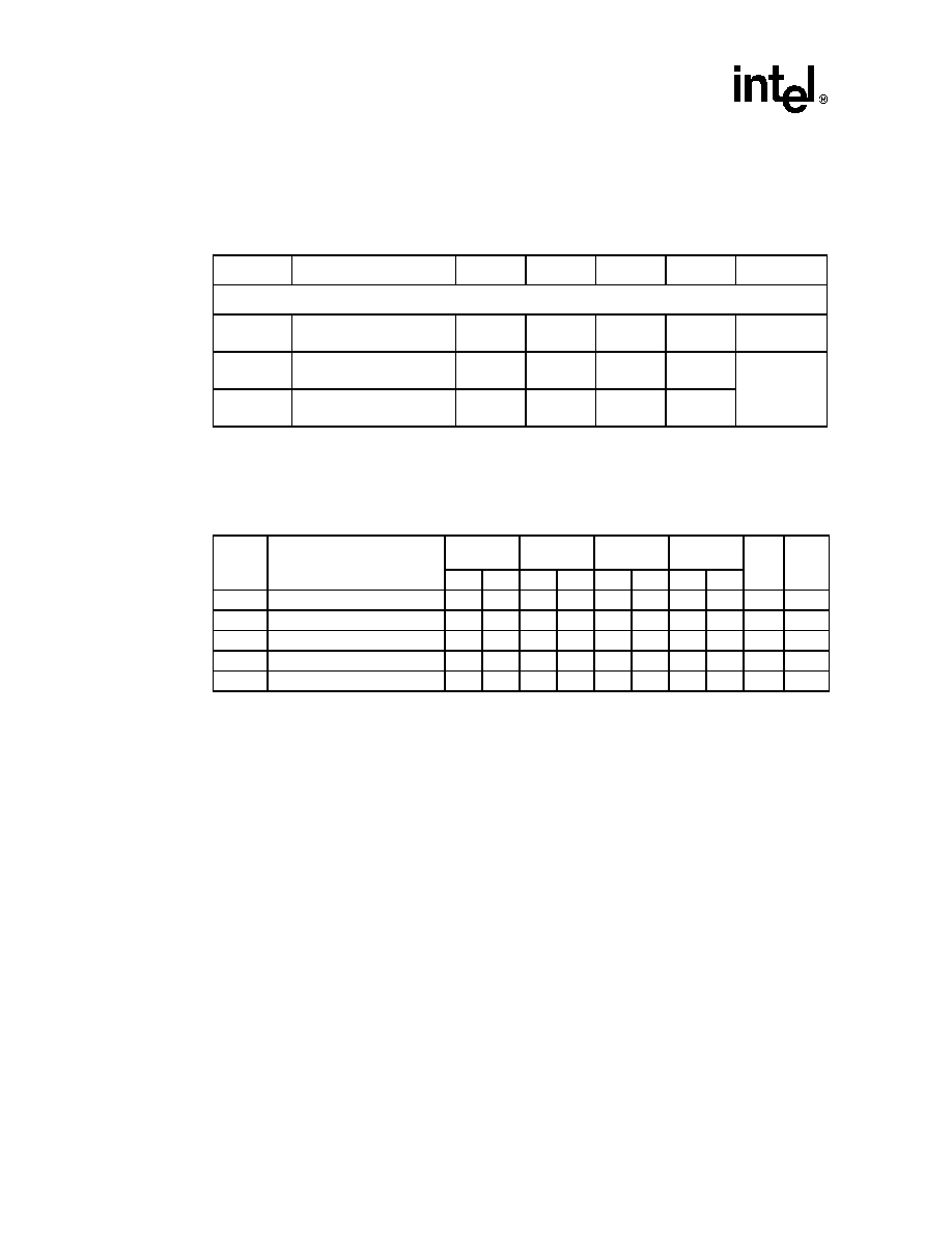
4.7
Targeted AC Specifications
Over recommended operating conditions.
4.7.1
Clock Signal Timings
Table 17.
AC Characteristics
Parameter
Description
Minimum
Type
Maximum
Unit
Conditions
Serial ATA Interface
Tr, Tf
Rise and Fall Time
(20%-80%)
130
--
260
ps
V
OUT
TXx output differential
peak-to-peak voltage swing
400
--
600
mVp-p
Note
1
1. Measured per Section 6.6.3 of the Serial ATA: High speed Serialized AT Attachment Specification, Revision 1.0e
V
IN
RXx input differential
peak-to-peak swing
200
--
2000
mVp-p
Table 18.
Clock Timings
Symbol
Parameter
64-Bit
PCI-X 133
64-Bit
PCI-X 66
32-Bit
PCI 66
32-Bit
PCI 33
Units Notes
Min
Max
Min
Max
Min
Max
Min
Max
T
F1
PCI clock Frequency
100
133
50
66
33
66
16
33
MHz
1
T
C1
PCI clock Cycle Time
7.5
10
15
20
15
30
30
60
ns
1, 3
T
CH1
PCI clock High Time
3
6
6
11
ns
T
CL1
PCI clock Low Time
3
6
6
11
ns
T
SR1
PCI clock Slew Rate
1.5
4
1.5
4
1.5
4
1
4
V/ns
2
NOTES:
1. The clock frequency may not change beyond the spread-spectrum limits except while P_RST# is asserted.
2. This slew rate must be met across the minimum peak-to-peak portion of the clock waveform.
3. The minimum clock period must not be violated for any single clock cycle, i.e., accounting for all system jitter.

Intel
Æ
31244 PCI-X to Serial ATA Controller
Electrical Specifications
Datasheet
April 28, 2003
35
4.7.2
PCI Interface Signal Timings
Table 19.
PCI Signal Timings
Symbol
Parameter
64-Bit
PCI-X 133
64-Bit
PCI-X 66
32-Bit
PCI 66
32-Bit
PCI 33
Units
Notes
Min Max Min Max Min Max Min Max
T
OV1
Clock to Output Valid Delay for
bused signals
0.7
3.8
0.7
3.8
1
6
2
11
ns
1, 2, 3
T
OV2
Clock to Output Valid Delay for
point to point signals
0.7
3.8
0.7
3.8
2
6
2
12
ns
1, 2, 3
T
OF
Clock to Output Float Delay
7
7
14
28
ns
1, 7
T
IS1
Input Setup to clock for bused
signals
1.2
1.7
3
7
ns
3, 4, 8
T
IS2
Input Setup to clock for point to
point signals
1.2
1.7
5
10,
12
ns
3, 4
T
IH1
Input Hold time from clock
0.5
0.5
0
0
ns
4
T
RST
Reset Active Time
1
1
1
1
ms
T
RF
Reset Active to output float
delay
40
40
40
40
ns
5, 6
T
IS3
P_REQ64# to Reset setup time
10
10
10
10
clocks
T
IH2
Reset to P_REQ64# hold time
0
50
0
50
0
50
0
50
ns
T
IS4
PCI-X initialization pattern to
Reset setup time
10
10
clocks
T
IH3
Reset to PCI-X initialization
pattern hold time
0
50
0
50
ns
NOTES:
1. See the timing measurement conditions in
Figure 8 "Output Timing Measurement Waveforms" on page 36
.
2. See
Figure 10 "PCI/X TOV(max) Rising Edge AC Test Load" on page 36
,
Figure 11 "PCI/X TOV(max)
Falling Edge AC Test Load" on page 37
and
Figure 12 "PCI/X TOV(min) AC Test Load" on page 37
.
3. Setup time for point-to-point signals applies to P_REQ# and GNT# only. All other signals are bused.
4. See the timing measurement conditions in
Figure 9 "Input Timing Measurement Waveforms" on page 36
.
5. P_RST# is asserted and deasserted asynchronously with respect to P_CLK.
6. All output drivers must be floated when P_RST# is active.
7. For purposes of Active/Float timing measurements, the HI-Z or "off" state is defined to be when the total
current delivered through the component pin is less than or equal to the leakage current specification.
8. Setup time applies only when the device is not driving the pin. Devices cannot drive and receive signals at
the same time.

Intel
Æ
31244 PCI-X to Serial ATA Controller
Electrical Specifications
36
April 28, 2003
Datasheet
Figure 8.
Output Timing Measurement Waveforms
Figure 9.
Input Timing Measurement Waveforms
Figure 10.
PCI/X T
OV(max)
Rising Edge AC Test Load
V
test
P_CLK
OUTPUT
FLOAT
Vtrise
OUTPUT
DELAY RISE
OUTPUT
DELAY FALL
V
tfall
T
OV
T
OV
T
OF
V
tl
V
th
P_CLK
INPUT
Valid
V
test
V
test
V
test
T
IS
T
IH
V
tl
V
th
V
th
V
tl
V
max
Output
Test
Point
10pF
25

Intel
Æ
31244 PCI-X to Serial ATA Controller
Electrical Specifications
Datasheet
April 28, 2003
37
Figure 11.
PCI/X T
OV(max)
Falling Edge AC Test Load
Figure 12.
PCI/X T
OV(min)
AC Test Load
Output
10pF
25
V
CC33
Test
Point
Output
Test
Point
10pF
1K
1K
V
CC33