Other brands and names are the property of their respective owners
Information in this document is provided in connection with Intel products Intel assumes no liability whatsoever including infringement of any patent or
copyright for sale and use of Intel products except as provided in Intel's Terms and Conditions of Sale for such products Intel retains the right to make
changes to these specifications at any time without notice Microcomputer Products may have minor variations to this specification known as errata
March 1992
COPYRIGHT
INTEL CORPORATION 1995
Order Number 240448-005
Intel387
TM
DX
MATH COPROCESSOR
Y
High Performance 80-Bit Internal
Architecture
Y
Implements ANSI IEEE Standard 754-
1985 for Binary Floating-Point
Arithmetic
Y
Expands Intel386
TM
DX CPU Data
Types to Include 32- 64- 80-Bit
Floating Point 32- 64-Bit Integers and
18-Digit BCD Operands
Y
Directly Extends Intel386
TM
DX CPU
Instruction Set to Include
Trigonometric Logarithmic
Exponential and Arithmetic Instructions
for All Data Types
Y
Upward Object-Code Compatible from
8087 and 80287
Y
Full-Range Transcendental Operations
for SINE COSINE TANGENT
ARCTANGENT and LOGARITHM
Y
Built-In Exception Handling
Y
Operates Independently of Real
Protected and Virtual-8086 Modes of
the Intel386
TM
DX Microprocessor
Y
Eight 80-Bit Numeric Registers Usable
as Individually Addressable General
Registers or as a Register Stack
Y
Available in 68-Pin PGA Package
Y
One Version Supports 16 MHz � 33 MHz
Speeds
(See Packaging Spec Order
231369)
The Intel387
TM
DX Math CoProcessor (MCP) is an extension of the Intel386
TM
microprocessor architecture
The combination of the Intel387 DX MCP with the Intel386
TM
DX Microprocessor dramatically increases the
processing speed of computer application software which utilize mathematical operations This makes an ideal
computer workstation platform for applications such as financial modeling and spreadsheets CAD CAM or
graphics
The Intel387 DX Math CoProcessor adds over seventy mnemonics to the Intel386 DX Microprocessor instruc-
tion set Specific Intel387 DX MCP math operations include logarithmic arithmetic exponential and trigono-
metric functions The Intel387 DX MCP supports integer extended integer floating point and BCD data
formats and fully conforms to the ANSI IEEE floating point standard
The Intel387 DX Math CoProcessor is object code compatible with the Intel387 SX MCP and upward object
code compatible from the 80287 and 8087 math coprocessors Object code for Intel386 DX Intel387 DX is
also compatible with the Intel486
TM
microprocessor The Intel387 DX MCP is manufactured on 1 micron
CHMOS IV technology and packaged in a 68-pin PGA package
240448 � 1
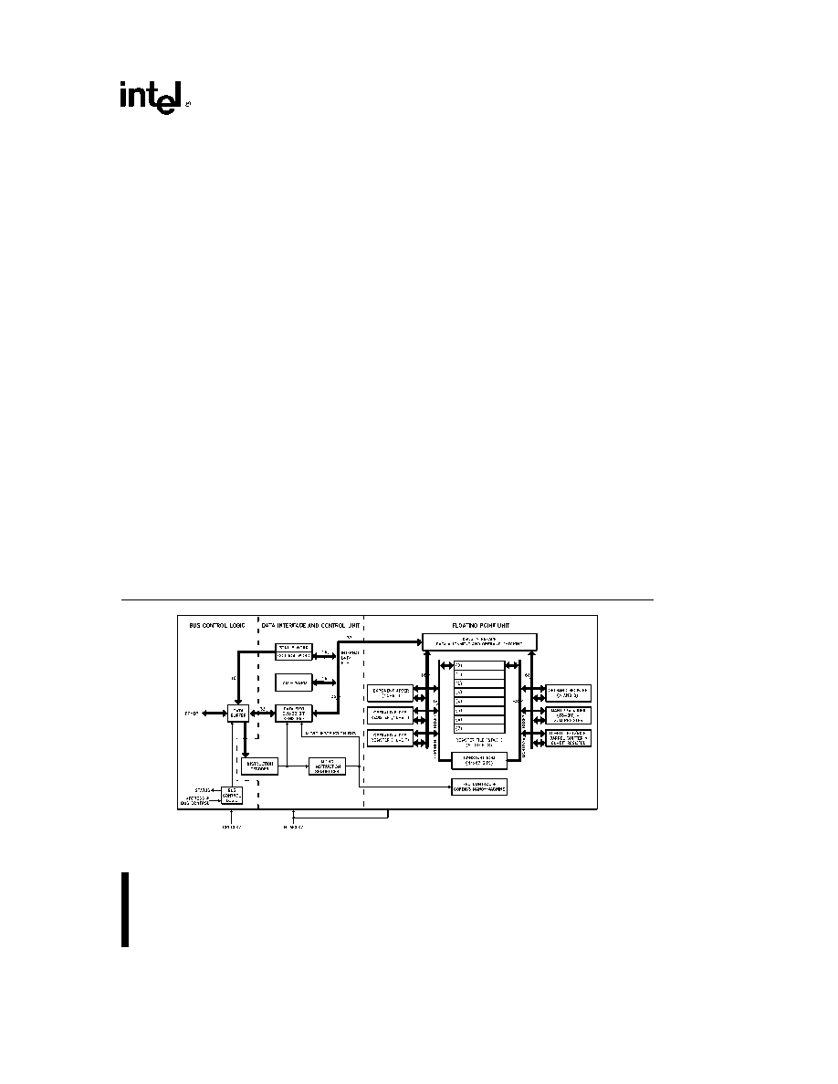
Figure 0 1 Intel387
TM
DX Math CoProcessor Block Diagram
1

Intel387
TM
DX Math CoProcessor
CONTENTS
PAGE
1 0 FUNCTIONAL DESCRIPTION
5
2 0 PROGRAMMING INTERFACE
6
2 1 Data Types
6
2 2 Numeric Operands
6
2 3 Register Set
8
2 3 1 Data Registers
8
2 3 2 Tag Word
8
2 3 3 Status Word
9
2 3 4 Instruction and Data Pointers
12
2 3 5 Control Word
14
2 4 Interrupt Description
14
2 5 Exception Handling
15
2 6 Initialization
15
2 7 8087 and 80287 Compatibility
16
2 7 1 General Differences
16
2 7 2 Exceptions
17
3 0 HARDWARE INTERFACE
17
3 1 Signal Description
17
3 1 1 Intel386
TM
DX CPU Clock 2 (CPUCLK2)
20
3 1 2 Intel387
TM
DX MCP Clock 2 (NUMCLK2)
20
3 1 3 Intel387
TM
DX MCP Clocking Mode (CKM)
20
3 1 4 System Reset (RESETIN)
21
3 1 5 Processor Extension Request (PEREQ)
21
3 1 6 Busy Status (BUSY )
21
3 1 7 Error Status (ERROR )
21
3 1 8 Data Pins (D31 � D0)
21
3 1 9 Write Read Bus Cycle (W R )
21
3 1 10 Address Strobe (ADS )
21
3 1 11 Bus Ready Input (READY )
22
3 1 12 Ready Output (READYO )
22
3 1 13 Status Enable (STEN)
22
3 1 14 MCP Select
1 (NPS1 )
22
3 1 15 MCP Select
2 (NPS2)
22
3 1 16 Command (CMD0 )
22
2
2

CONTENTS
PAGE
3 2 Processor Architecture
22
3 2 1 Bus Control Logic
23
3 2 2 Data Interface and Control Unit
23
3 2 3 Floating Point Unit
23
3 3 System Configuration
23
3 3 1 Bus Cycle Tracking
24
3 3 2 MCP Addressing
24
3 3 3 Function Select
24
3 3 4 CPU MCP Synchronization
24
3 3 5 Synchronous or Asynchronous Modes
25
3 3 6 Automatic Bus Cycle Termination
25
3 4 Bus Operation
25
3 4 1 Nonpipelined Bus Cycles
26
3 4 1 1 Write Cycle
26
3 4 1 2 Read Cycle
26
3 4 2 Pipelined Bus Cycles
27
3 4 3 Bus Cycles of Mixed Type
28
3 4 4 BUSY
and PEREQ Timing Relationship
28
4 0 ELECTRICAL DATA
30
4 1 Absolute Maximum Ratings
30
4 2 DC Characteristics
30
4 3 AC Characteristics
31
5 0 Intel387
TM
DX MCP EXTENSIONS TO THE Intel386
TM
DX CPU INSTRUCTION
SET
36
APPENDIX A
COMPATIBILITY BETWEEN THE 80287 MCP AND THE 8087
A-1
FIGURES
Figure 0 1 Intel387
TM
DX Math Coprocessor Block Diagram
1
Figure 1 1 Intel386
TM
DX Microprocessor and Intel387
TM
DX Math Coprocessor Register
Set
5
Figure 2 1 Intel387
TM
DX MCP Tag Word
8
Figure 2 2 MCP Status Word
9
Figure 2 3 Protected Mode Intel387
TM
DX MCP Instruction and Data Pointer Image in
Memory 32-Bit Format
12
Figure 2 4 Real Mode Intel387
TM
DX MCP Instruction and Data Pointer Image in Memory 32-
Bit Format
13
Figure 2 5 Protected Mode Intel387
TM
DX MCP Instruction and Data Pointer Image in
Memory 16-Bit Format
13
Figure 2 6 Real Mode Intel387
TM
DX MCP Instruction and Data Pointer Image in Memory 16-
Bit Format
13
Figure 2 7 Intel387
TM
DX MCP Control Word
14
Figure 3 1 Intel387
TM
DX MCP Pin Configuration
19
3
3

CONTENTS
PAGE
FIGURES
(Continued)
Figure 3 2
Asynchronous Operation
20
Figure 3 3
Intel386
TM
DX Microprocessor and Intel387
TM
DX MCP Coprocessor System
Configuration
23
Figure 3 4
Bus State Diagram
25
Figure 3 5
Nonpipelined Read and Write Cycles
27
Figure 3 6
Fastest Transitions to and from Pipelined Cycles
28
Figure 3 7
Pipelined Cycles with Wait States
29
Figure 3 8
STEN BUSY
and PEREQ Timing Relationship
29
Figure 4 0a Typical Output Valid Delay vs Load Capacitance at Max Operating
Temperature
32
Figure 4 0b Typical Output Rise Time vs Load Capacitance at Max Operating
Temperature
32
Figure 4 1
CPUCLK2 NUMCLK2 Waveform and Measurement Points for Input Output A C
Specifications
33
Figure 4 2
Output Signals
33
Figure 4 3
Input and I O Signals
34
Figure 4 4
RESET Signal
34
Figure 4 5
Float from STEN
34
Figure 4 6
Other Parameters
35
TABLES
Table 2 1
Intel387
TM
DX MCP Data Type Representation in Memory
7
Table 2 2
Condition Code Interpretation
10
Table 2 3
Condition Code Interpretation after FPREM and FPREM1 Instructions
11
Table 2 4
Condition Code Resulting from Comparison
11
Table 2 5
Condition Code Defining Operand Class
11
Table 2 6
Intel386
TM
DX Microprocessor Interrupt Vectors Reserved for MCP
15
Table 2 7
Exceptions
16
Table 3 1
Intel387
TM
DX MCP Pin Summary
18
Table 3 2
Intel387
TM
DX MCP Pin Cross-Reference
18
Table 3 3
Output Pin Status after Reset
21
Table 3 4
Bus Cycles Definition
24
Table 4 1
DC Specifications
30
Table 4 2a Combinations of Bus Interface and Execution Speeds
31
Table 4 2b Timing Requirements of the Execution Unit
31
Table 4 2c Timing Requirements of the Bus Interface Unit
31
Table 4 3
Other Parameters
35
4
4

Intel387
TM
DX MATH COPROCESSOR
Intel386
TM
DX Microprocessor Registers
GENERAL REGISTERS
31
15
0
EAX
AX
AH
AL
EBX
BX
BH
BL
ECX
CX
CH
CL
EDX
DX
DH
DL
ESI
SI
EDI
DI
EBP
BP
ESP
SP
SEGMENT REGISTERS
15
0
CS
SS
DS
ES
FS
GS
31
0
EIP
EFLAGS
l
Intel387
TM
DX MCP Data Registers
l
Tag
Field
l
79
78
64
63
0
1
0
l
l
R0
Sign
Exponent
Significand
l
R1
l
R2
l
l
R3
l
R4
l
R5
l
l
R6
l
R7
l
l
l
15
0
47
0
l
Control Register
Instruction Pointer (in i386
TM
DX CPU)
l
Status Register
Data Pointer (in i386
TM
DX CPU)
l
l
Tag Word
l
l
l
l
l
Figure 1 1 Intel386
TM
DX Microprocessor and Intel387
TM
DX Math Coprocessor Register Set
1 0 FUNCTIONAL DESCRIPTION
The Intel387
TM
DX Math Coprocessor provides
arithmetic instructions for a variety of numeric data
types in Intel386
TM
DX Microprocessor systems It
also executes numerous built-in transcendental
functions (e g tangent sine cosine and log func-
tions) The Intel387 DX MCP effectively extends the
register and instruction set of a Intel386 DX Micro-
processor system for existing data types and adds
several new data types as well Figure 1 1 shows the
model of registers visible to programs Essentially
the Intel387 DX MCP can be treated as an additional
resource or an extension to the Intel386 DX Micro-
processor The Intel386 DX Microprocessor togeth-
er with a Intel387 DX MCP can be used as a single
unified system
The Intel387 DX MCP works the same whether the
Intel386 DX Microprocessor is executing in real-ad-
dress mode protected mode or virtual-8086 mode
All memory access is handled by the Intel386 DX
Microprocessor the Intel387 DX MCP merely oper-
ates on instructions and values passed to it by the
Intel386 DX Microprocessor Therefore the Intel387
DX MCP is not sensitive to the processing mode of
the Intel386 DX Microprocessor
In real-address mode and virtual-8086 mode the In-
tel386 DX Microprocessor and Intel387 DX MCP are
completely upward compatible with software for
8086 8087 80286 80287 real-address mode and
Intel386 DX Microprocessor and 80287 Coproces-
sor real-address mode systems
In protected mode the Intel386 DX Microprocessor
and Intel387 DX MCP are completely upward com-
patible with software for 80286 80287 protected
mode and Intel386 DX Microprocessor and 80287
Coprocessor protected mode systems
The only differences of operation that may appear
when 8086 8087 programs are ported to a protect-
ed-mode Intel386 DX Microprocessor and Intel387
DX MCP system (
not
using virtual-8086 mode) is in
the format of operands for the administrative instruc-
tions FLDENV
FSTENV
FRSTOR and FSAVE
These instructions are normally used only by excep-
tion handlers and operating systems not by applica-
tions programs
The Intel387 DX MCP contains three functional units
that can operate in parallel to increase system per-
formance The Intel386 DX Microprocessor can be
transferring commands and data to the MCP
bus
control logic
for the next instruction while the MCP
floating-point unit
is performing the current numeric
instruction
5
5