 | –≠–ª–µ–∫—Ç—Ä–æ–Ω–Ω—ã–π –∫–æ–º–ø–æ–Ω–µ–Ω—Ç: 80960MC | –°–∫–∞—á–∞—Ç—å:  PDF PDF  ZIP ZIP |
© INTEL CORPORATION, 1997
September, 1997
Order Number: 273123-001
PRELIMINARY
80960MC
EMBEDDED 32-BIT MICROPROCESSOR
WITH INTEGRATED FLOATING-POINT UNIT
AND MEMORY MANAGEMENT UNIT
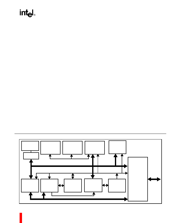
Figure 1. The 80960MC Processor's Highly Parallel Architecture
Commercial
s
High-Performance Embedded Architecture
-- 25 MIPS Burst Execution at 25 MHz
-- 9.4 MIPS* Sustained Execution at
25 MHz
s
On-Chip Floating Point Unit
-- Supports IEEE 754 Floating Point
Standard
-- Full Transcendental Support
-- Four 80-Bit Registers
-- 13.6 Million Whetstones/s
(Single Precision) at 25 MHz
s
512-Byte On-Chip Instruction Cache
-- Direct Mapped
-- Parallel Load/Decode for Uncached
Instructions
s
Multiple Register Sets
-- Sixteen Global 32-Bit Registers
-- Sixteen Local 32-Bit Registers
-- Four Local Register Sets Stored
On-Chip (Sixteen 32-Bit Registers per
Set)
-- Register Scoreboarding
s
On-Chip Memory Management Unit
-- 4 Gbyte Virtual Address Space per
Task
-- 4 Kbyte Pages with Supervisor/User
Protection
s
Built-in Interrupt Controller
-- 32 Priority Levels
-- 248 Vectors
-- Supports M8259A
-- 3.4
µ
s Latency @ 25 MHz
s
Easy to Use, High Bandwidth 32-Bit Bus
-- 66.7 Mbytes/s Burst
-- Up to 16 Bytes Transferred per Burst
s
Multitasking and Multiprocessor Support
-- Automatic Task dispatching
-- Prioritized Task Queues
s
Advanced Package Technology
-- 132-Lead Ceramic Pin Grid Array
SIXTEEN
32-BIT GLOBAL
REGISTERS
64- BY 32-BIT
LOCAL
REGISTER
CACHE
32-BIT
INSTRUCTION
EXECUTION
UNIT
INSTRUCTION
FETCH UNIT
512-BYTE
INSTRUCTION
CACHE
INSTRUCTION
DECODER
MICRO-
INSTRUCTION
SEQUENCER
MICRO-
INSTRUCTION
ROM
32-BIT
BUS CONTROL
LOGIC
32-BIT
BURST
BUS
FOUR
80-BIT FP
REGISTERS
80-BIT
FPU
MMU

Information in this document is provided in connection with Intel products. No license, express or implied, by
estoppel or otherwise, to any intellectual property rights is granted by this document. Except as provided in
Intel's Terms and Conditions of Sale for such products, Intel assumes no liability whatsoever, and Intel
disclaims any express or implied warranty, relating to sale and/or use of Intel products including liability or
warranties relating to fitness for a particular purpose, merchantability, or infringement of any patent, copyright
or other intellectual property right. Intel products are not intended for use in medical, life saving, or life
sustaining applications. Intel may make changes to specifications and product descriptions at any time, without
notice. Contact your local Intel sales office or your distributor to obtain the latest specifications and before
placing your product order.
Intel retains the right to make changes to specifications and product descriptions at any time, without notice.
*Third party brands and names are the property of their respective owners.
Copies of documents which have an ordering number and are referenced in this document, or other Intel
literature, may be obtained from:
Intel Corporation
P.O. Box 7641
Mt. Prospect IL 60056-7641
or call 1-800-879-4683
Many documents are available for download from Intel's website at http://www.intel.com
Copyright © Intel Corporation 1997

80960MC
iii
1.0 THE i960
Æ
MC PROCESSOR ................................................................................................................. .. 1
1.1 Key Performance Features ................................................................................................................. 2
1.1.1 Memory Space And Addressing Modes ................................................................................... 4
1.1.2 Data Types ............................................................................................................. .................. 4
1.1.3 Large Register Set ..................................................................................................... .............. 4
1.1.4 Multiple Register Sets .............................................................................................................. 5
1.1.5 Instruction Cache ..................................................................................................................... 5
1.1.6 Register Scoreboarding ................................................................................................. .......... 5
1.1.7 Memory Management and Protection ...................................................................................... 6
1.1.8 Floating-Point Arithmetic .............................................................................................. ............ 6
1.1.9 Multitasking Support ................................................................................................................ 7
1.1.10 Synchronization and Communication .................................................................................... 7
1.1.11 High Bandwidth Local Bus ..................................................................................................... 7
1.1.12 Multiple Processor Support .................................................................................................... 7
1.1.13 Interrupt Handling .................................................................................................... .............. 8
1.1.14 Debug Features ..................................................................................................................... 8
1.1.15 Fault Detection ....................................................................................................................... 8
1.1.16 Inter-Agent Communications (IAC) ...................................................................................... .. 9
1.1.17 Built-in Testability ................................................................................................................... 9
1.1.18 Compatibility with 80960K-Series ...................................................................................... .... 9
1.1.19 CHMOS ................................................................................................................. ................. 9
2.0 ELECTRICAL SPECIFICATIONS ................................................................................................ ........... 13
2.1 Power and Grounding ...................................................................................................... ................. 13
2.2 Power Decoupling Recommendations ......................................................................................... .... 13
2.3 Connection Recommendations ........................................................................................................ 13
2.4 Characteristic Curves ....................................................................................................................... 13
2.5 Test Load Circuit .............................................................................................................................. 16
2.7 DC Characteristics ....................................................................................................... ..................... 17
2.6 Absolute Maximum Ratings .............................................................................................................. 17
2.8 AC Specifications ............................................................................................................................. 18
2.9 Design Considerations ..................................................................................................................... 22
3.0 MECHANICAL DATA .............................................................................................................................. 22
3.1 Packaging ......................................................................................................................................... 22
3.1.1 Pin Assignment ...................................................................................................................... 22
3.2 Pinout ............................................................................................................................................... 26
3.3 Package Thermal Specification ........................................................................................................ 28
4.0 WAVEFORMS ......................................................................................................................................... 30
5.0 REVISION HISTORY ............................................................................................................................... 35

80960MC
iv
FIGURES
Figure 1.
80960MC Programming Environment ........................................................................................ 1
Figure 2.
Instruction Formats .................................................................................................................... 4
Figure 3.
Multiple Register Sets Are Stored On-Chip ............................................................................... 6
Figure 4.
Connection Recommendations for Low Current Drive Network .............................................. 13
Figure 5.
Connection Recommendations for High Current Drive Network .............................................. 13
Figure 6.
Typical Supply Current vs. Case Temperature ........................................................................ 14
Figure 7.
Typical Current vs. Frequency (Room Temp) .......................................................................... 14
Figure 8.
Typical Current vs. Frequency (Hot Temp) .............................................................................. 15
Figure 9.
Worst-Case Voltage vs. Output Current on Open-Drain Pins .................................................. 15
Figure 10.
Capacitive Derating Curve ....................................................................................................... 15
Figure 11.
Test Load Circuit for Three-State Output Pins ......................................................................... 16
Figure 12.
Test Load Circuit for Open-Drain Output Pins ......................................................................... 16
Figure 13.
Drive Levels and Timing Relationships for 80960MC Signals ................................................. 18
Figure 14.
Timing Relationship of L-Bus Signals ................................................................................ ...... 19
Figure 15.
System and Processor Clock Relationship ............................................................................. . 19
Figure 16.
Processor Clock Pulse (CLK2) ................................................................................................ 21
Figure 17.
RESET Signal Timing .............................................................................................................. 21
Figure 18.
HOLD Timing ........................................................................................................................... 22
Figure 19.
132-Lead Pin-Grid Array (PGA) Package ................................................................................ 23
Figure 20.
80960MC PGA Pinout--View from Bottom (Pins Facing Up) .................................................. 24
Figure 21.
80960MC PGA Pinout--View from Top (Pins Facing Down) .................................................. 25
Figure 22.
25 MHz Maximum Allowable Ambient Temperature ................................................................ 29
Figure 23.
Non-Burst Read and Write Transactions Without Wait States ................................................. 30
Figure 24.
Burst Read and Write Transaction Without Wait States .......................................................... 31
Figure 25.
Burst Write Transaction with 2, 1, 1, 1 Wait States .................................................................. 32
Figure 26.
Accesses Generated by Quad Word Read Bus Request, Misaligned Two Bytes from
Quad Word Boundary (1, 0, 0, 0 Wait States) ......................................................................... 33
Figure 27.
Interrupt Acknowledge Transaction ......................................................................................... 34
Figure 28.
Bus Exchange Transaction (PBM = Primary Bus Master, SBM = Secondary Bus Master) ..... 35
TABLES
Table 1.
80960MC Instruction Set ........................................................................................................... 3
Table 2.
Memory Addressing Modes ....................................................................................................... 4
Table 3.
Sample Floating-Point Execution Times (µs) at 25 MHz ........................................................... 7
Table 4.
80960MC Pin Description: L-Bus Signals .................................................................................. 9
Table 5.
80960MC Pin Description: Support Signals ............................................................................. 11
Table 6.
DC Characteristics ................................................................................................................... 17
Table 7.
80960MC AC Characteristics (25 MHz) ...................................................................................20
Table 8.
80960MC PGA Pinout -- In Pin Order .....................................................................................26
Table 9.
80960MC PGA Pinout -- In Signal Order ................................................................................ 27
Table 10.
80960MC PGA Package Thermal Characteristics ................................................................... 28

PRELIMINARY
1
80960MC
1.0
THE i960
Æ
MC PROCESSOR
The 80960MC, a member of Intel's i960
Æ
32-bit
processor family, is ideally suited for embedded
applications. It includes a 512-byte instruction cache
and a built-in interrupt controller. The 80960MC has
a large register set, multiple parallel execution units
and a high-bandwidth burst bus. Using advanced
RISC technology, this processor is capable of
execution rates in excess of 9.4 million instructions
per second
*
. The 80960MC is well-suited for a wide
range of applications including non-impact printers,
I/O control and specialty instrumentation. The
embedded market includes applications as diverse
as industrial automation, avionics, image
processing, graphics and networking. These types of
applications require high integration, low power
consumption, quick interrupt response times and
* Relative to Digital Equipment Corporation's VAX-11/780*
at 1 MIPS
high performance. Since time to market is critical,
embedded processors must be easy to use in both
hardware and software designs.
All members of the i960 processor family share a
common core architecture which utilizes RISC tech-
nology so that, except for special functions, the
family members are object-code compatible. Each
new processor in the family adds its own special set
of functions to the core to satisfy the needs of a
specific application or range of applications in the
embedded market.
The 80960MC includes an integrated Floating Point
Unit (FPU), a Memory Management Unit (MMU),
multitasking support, and multiprocessor support.
Two commercial members of the i960
Æ
family
provide similar features: the 80960KB processor with
integrated FPU and the 80960KA without floating-
point.
Figure 1. 80960MC Programming Environment
INSTRUCTION CACHE
INSTRUCTION
STREAM
FETCH
LOAD
STORE
SIXTEEN 32-BIT GLOBAL REGISTERS
g0
g15
SIXTEEN 32-BIT LOCAL REGISTERS
REGISTER CACHE
FOUR 80-BIT FLOATING POINT REGISTERS
r0
r15
CONTROL REGISTERS
INSTRUCTION
EXECUTION
INSTRUCTION
POINTER
ARITHMETIC
CONTROLS
PROCESS
CONTROLS
TRACE
CONTROLS
ARCHITECTURALLY
DEFINED
DATA STRUCTURES
FFFF FFFFH
0000 0000H
ADDRESS SPACE
PROCESSOR STATE
REGISTERS