Intel Corporation assumes no responsibility for the use of any circuitry other than circuitry embodied in an Intel product. No other circuit patent
licenses are implied. Information contained herein supersedes previously published specifications on these devices from Intel.
© INTEL CORPORATION, 1993
November 1993
Order Number: 272206-002
80960SA
EMBEDDED 32-BIT MICROPROCESSOR
WITH 16-BIT BURST DATA BUS
The 80960SA is a member of Intel's i960
Æ
32-bit processor family, which is designed especially for low cost
embedded applications. It includes a 512-byte instruction cache and a built-in interrupt controller. The 80960SA
has a large register set, multiple parallel execution units and a 16-bit burst bus. Using advanced RISC
technology, this high performance processor is capable of execution rates in excess of 7.5 million instructions
per second
*
. The 80960SA is well-suited for a wide range of cost sensitive embedded applications including
non-impact printers, network adapters and I/O controllers.
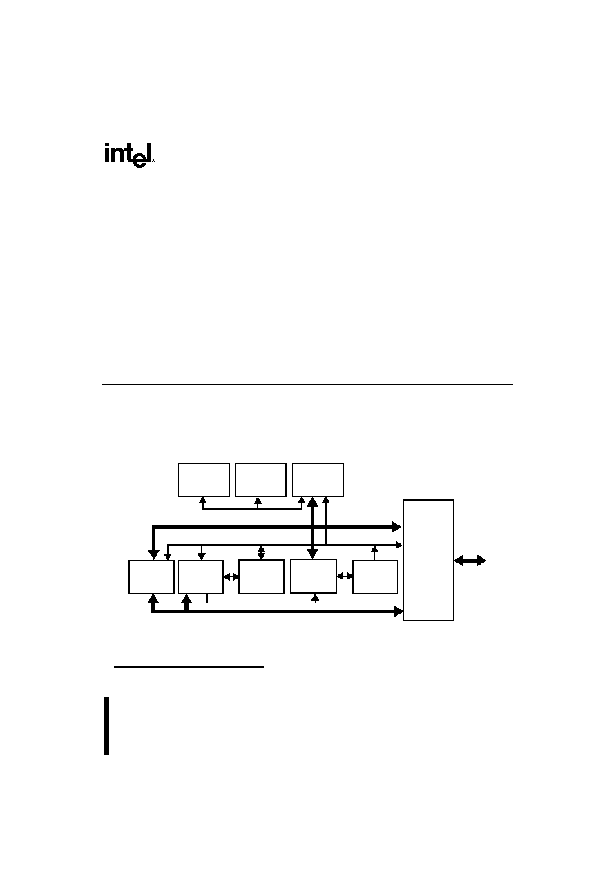
Figure 1. The 80960SA Processor's Highly Parallel Architecture
* Relative to Digital Equipment Corporation's VAX-11/780 at 1 MIPS (VAX-11TM is a trademark of Digital Equipment
Corporation)
s
High-Performance Embedded
Architecture
-- 20 MIPS* Burst Execution at 20 MHz
-- 7.5 MIPS Sustained Execution
at 20 MHz
s
512-Byte On-Chip Instruction Cache
-- Direct Mapped
-- Parallel Load/Decode for Uncached
Instructions
s
Multiple Register Sets
-- Sixteen Global 32-Bit Registers
-- Sixteen Local 32-Bit Registers
-- Four Local Register Sets Stored
On-Chip
-- Register Scoreboarding
s
Pin Compatible with 80960SB
s
Built-in Interrupt Controller
-- 4 Direct Interrupt Pins
-- 31 Priority Levels, 256 Vectors
s
Easy to Use, High Bandwidth 16-Bit Bus
-- 32 Mbytes/s Burst
-- Up to 16 Bytes Transferred per Burst
s
32-Bit Address Space, 4 Gigabytes
s
80-Lead Quad Flat Pack (EIAJ QFP)
-- 84-Lead Plastic Leaded Chip Carrier
(PLCC)
s
Software Compatible with
80960KA/KB/CA/CF Processors
INSTRUCTION
FETCH UNIT
512-BYTE
INSTRUCTION
CACHE
INSTRUCTION
DECODER
MICRO-
INSTRUCTION
SEQUENCER
MICRO-
INSTRUCTION
ROM
32-BIT
BUS
CONTROL
LOGIC
32-BIT
INSTRUCTION
EXECUTION
UNIT
64- BY 32-BIT
LOCAL
REGISTER
CACHE
SIXTEEN
32-BIT GLOBAL
REGISTERS
32-BIT
ADDRESS
16-BIT
BURST
BUS

ii
CONTENTS
PAGE
1.0 THE i960
Æ
PROCESSOR ...........................................................................................................................1
1.1 Key Performance Features .................................................................................................................2
1.1.1 Memory Space And Addressing Modes ...................................................................................4
1.1.2 Data Types ...............................................................................................................................4
1.1.3 Large Register Set ...................................................................................................................4
1.1.4 Multiple Register Sets ..............................................................................................................5
1.1.5 Instruction Cache .....................................................................................................................6
1.1.6 Register Scoreboarding ...........................................................................................................6
1.1.7 High Bandwidth Bus ................................................................................................................6
1.1.8 Interrupt Handling ....................................................................................................................6
1.1.9 Debug Features .......................................................................................................................6
1.1.10 Fault Detection .......................................................................................................................7
1.1.11 Built-in Testability ....................................................................................................................7
1.1.12 CHMOS .................................................................................................................................. 7
2.0 ELECTRICAL SPECIFICATIONS............................................................................................................. 11
2.1 Power and Grounding ....................................................................................................................... 11
2.2 Power Decoupling Recommendations .............................................................................................. 11
2.3 Connection Recommendations ......................................................................................................... 11
2.4 Characteristic Curves ....................................................................................................................... 11
2.5 Test Load Circuit ............................................................................................................................... 13
2.6 ABSOLUTE MAXIMUM RATINGS* .................................................................................................. 14
2.7 DC Characteristics ............................................................................................................................ 14
2.8 AC Specifications .............................................................................................................................. 15
3.0 MECHANICAL DATA................................................................................................................................ 21
3.1 Packaging ......................................................................................................................................... 21
3.2 Pin Assignment ................................................................................................................................. 21
3.3 Pinout ................................................................................................................................................ 23
3.4 Package Thermal Specifications ...................................................................................................... 27
3.5 Stepping Register Information .......................................................................................................... 27
4.0 WAVEFORMS ........................................................................................................................................... 28
5.0 REVISION HISTORY ................................................................................................................................ 34
80960SA
EMBEDDED 32-BIT MICROPROCESSOR
WITH 16-BIT BURST DATA BUS

iii
LIST OF FIGURES
PAGE
Figure 1
The 80960SA Processor's Highly Parallel Architecture ................................................................ 0
Figure 2
80960SA Programming Environment ........................................................................................... 1
Figure 3
Instruction Formats ...................................................................................................................... 4
Figure 4
Multiple Register Sets Are Stored On-Chip .................................................................................. 5
Figure 5
Connection Recommendation for LOCK .................................................................................... 11
Figure 6
Typical Supply Current vs. Case Temperature ........................................................................... 12
Figure 7
Typical Current vs. Frequency (Room Temp) ............................................................................. 12
Figure 8
Typical Current vs. Frequency (Hot Temp) ................................................................................. 13
Figure 9
Capacitive Derating Curve ......................................................................................................... 13
Figure 10
Test Load Circuit for Three-State Output Pins ............................................................................ 13
Figure 11
Drive Levels and Timing Relationships for 80960SA Signals ..................................................... 15
Figure 12
Processor Clock Pulse (CLK2) ................................................................................................... 19
Figure 13
RESET Signal Timing ................................................................................................................. 19
Figure 14
HOLD Timing .............................................................................................................................. 20
Figure 15
80-Lead EIAJ Quad Flat Pack (QFP) Package .......................................................................... 21
Figure 16
84-Lead Plastic Leaded Chip Carrier (PLCC) Package ............................................................. 22
Figure 17
Non-Burst Read and Write Transactions Without Wait States .................................................... 28
Figure 18
Quad Word Burst Read Transaction With 1, 0, 0, 0, 0, 0, 0, 0 Wait States ................................ 29
Figure 19
Burst Write Transaction With 2, 1, 1, 1 Wait States (6-8 Bytes Transferred) .............................. 30
Figure 20
Accesses Generated by Quad Word Read Bus Request,
Misaligned One Byte from Quad Word Boundary 1, 0, 0, 0, 0, 0, 0, 0 Wait States ..................... 31
Figure 21
Interrupt Acknowledge Cycle ...................................................................................................... 32
Figure 22
Cold Reset Waveform ................................................................................................................ 33
LIST OF TABLES
Table 1
80960SA Instruction Set .............................................................................................................. 3
Table 2
Memory Addressing Modes ......................................................................................................... 4
Table 3
80960SA Pin Description: Bus Signals ........................................................................................ 8
Table 4
80960SA Pin Description: Support Signals ................................................................................ 10
Table 5
DC Characteristics ..................................................................................................................... 14
Table 6
80960SA AC Characteristics (10 MHz) ...................................................................................... 16
Table 7
80960SA AC Characteristics (16 MHz) ...................................................................................... 17
Table 8
80960SA AC Characteristics (20 MHz) ...................................................................................... 18
Table 9
80960SA QFP Pinout -- In Pin Order ........................................................................................ 23
Table 10
80960SA QFP Pinout -- In Signal Order ................................................................................... 24
Table 11
80960SA PLCC Pinout -- In Pin Order ...................................................................................... 25
Table 12
80960SA PLCC Pinout -- In Signal Order ................................................................................. 26
Table 13
80960SA QFP Package Thermal Characteristics ...................................................................... 27
Table 14
80960SA PLCC Package Thermal Characteristics .................................................................... 27
Table 15
Die Stepping Cross Reference ................................................................................................... 27

