 | –≠–ª–µ–∫—Ç—Ä–æ–Ω–Ω—ã–π –∫–æ–º–ø–æ–Ω–µ–Ω—Ç: SK70744 | –°–∫–∞—á–∞—Ç—å:  PDF PDF  ZIP ZIP |
Document Outline
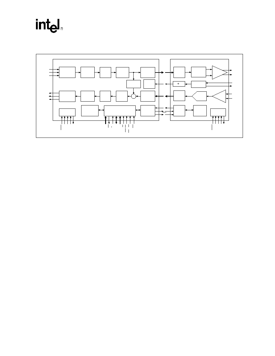
- Figure 1. SK70740/44 Block Diagram
- 1.0 Pin Assignments and Signal Descriptions
- 2.0 General Functional Description
- 3.0 AFE Functional Description
- 4.0 Transceiver/Framer Functional Description
- 5.0 Register Definitions
- 5.1 AFE Registers
- 5.2 Transceiver/Framer Registers
- 5.3 PAM Transceiver Registers
- Table 12. Main Control Register 0, MAIN0, R/W, Address = 00h, Default = 00h
- Table 13. Main Control Register 1, MAIN1, R/W Address = 01h, Default = 20h
- Table 14. Activation Mode Control Register, ACT_MODE, R/W, Address = 02h, Default = 00h
- 5.3.1 Registers 03h through 09h are Reserved
- Table 15. AFE Control Register, AFE_CTL, R/W, Address 0Ah, Default = FFh
- Table 16. AFE Address Register, AFE_ADD1 , R/W, Address = 0Bh, Default = 80h
- Table 17. Interrupt Mask Register, INT_MSK1, R/W, Address = 0Ch, Default = FFh
- Table 18. Interrupt State Register, INT_ST1, R/W, Address = 0Dh, Default = 00h �
- Table 19. Hardware Configuration Register, HW_CFG, R, Address = 0Eh, Default = F0h
- 5.3.2 Registers 0Fh through 17h are Reserved
- Table 20. Rate Select 0 Register, RATE_SEL0, R/W, Address = 18h, Default = AAh
- Table 21. Rate Select 1 Register, RATE_SEL1, R/W, Address = 19h, Default = AAh
- Table 22. Rate Select 2 Register, RATE_SEL2, R/W, Address = 1Ah, Default = ABh
- 5.3.3 Registers 1Bh through 21h are Reserved
- 5.3.4 Registers 23h and 24h are Reserved
- 5.3.5 Registers 26h through 2Ch are Reserved
- Table 25. AFE Status Register, AFE_STAT, R/W, Address = 2Dh, Default = 00h
- Table 26. Soft Decision (LSB) Register, SFT0, R, Address = 2Eh, Default = 00 h
- Table 27. Soft Decision (MSB) Register, SFT1, R, Address = 2Fh, Default = 00h
- Table 28. PLL Control Register, PLL_CTL, R/W, Address = 30h, Default = 00h
- Table 29. Main Control Register 2, MAIN2, R/W, Address = 31h, Default = 01h
- Table 30. Miscellaneous Control Register 1, MISC1, R/W, Address = 32h, Default = 00h
- Table 31. Wander Reduction Control Register, HTMCR, R/W, Address = 33h, Default = 00h
- 5.3.6 Registers 34h through 7Fh are Reserved
- 5.4 FEC Registers
- 5.4.1 FEC Encoder/Decoder Configuration Registers
- Table 32. Code Generator Select, CGSEL, R/W, Address = 80h, Default = 00h
- Table 33. Code Generator 1, CG1, R/W, Address = 81h, Default = DAh
- Table 34. Code Generator 2, CG2, R/W, Address = 82h Default = CDh
- Table 35. Code Generator 3, CG3, R/W, Address = 83h, Default = 08h
- Table 36. FEC Trace Back, FECTB, R/W, Address = 84h, Default = 00h
- 5.4.2 FEC Noise Register
- 5.4.3 Registers 86h through 92h are Reserved
- 5.4.4 Registers 94h through 9Fh are Reserved
- 5.5 Framer Transmit Registers
- Table 39. Framer Payload Rate, PLRATE, R/W, Address = A0h, Default = 18h
- Table 40. Reference Transmit Water Level, HTFWL, R/W, Address = A1h, Default = 2Eh
- Table 41. Actual Transmit Water Level, TFWL, R, Address = A2h
- Table 42. Transmit Control Register, HTFCR, R/W, Address = A3h, Default = 08h�
- Table 43. Transmit Test Control Register, HTFTCR, R/W, Address = A4h, Default = 00h
- Table 44. Transmit Data Byte Selection Register, HTFBSR, R/W, Address = A5h, Default = 00
- Table 45. Data Read Sample (High) Register, HTFRSRH, R, Address = A6h
- Table 46. Data Read Sample (Low) Register, HTFRSRL, R, Address = A7h
- Table 47. Transmit Frame Control Register, HTFTMR, R/W, Address = A8h, Default = 00h
- Table 48. All 1ês / 0ês Control
- Table 49. Transmit Sync Word (First 8 bits), HTFFSW1, R/W, Address = A9h Default = 00h
- Table 50. Transmit Sync Word (Last 2 bits), HTFFSW2, R/W, Address = AAh Default = 00h
- 5.5.1 Registers ABh through B0h are Reserved
- Table 51. HDSL2 Transmit Overhead Register 1, HTFHOH1, R/W, Address = B1h, Default = 00h
- Table 52. HDSL2 Transmit Overhead Register 2, HTFHOH2, R/W, Address=B2h, Default=00h�
- Table 53. HDSL2 Transmit Overhead Register 3, HTFHOH3, R/W, Address = B3h, Default = 00h
- Table 54. HDSL2 Transmit Overhead Register 4, HTFHOH4, R/W, Address = B4h, Default = 00h
- 5.6 Framer Receive Registers
- Table 55. Receive Control Register, HRFCR, R/W, Address = C0h, Default 00h
- Table 56. Receive Test Control Register, HRFTCR, R/W, Address = C1h, Default = 00h
- 5.6.1 Receive FIFO Water Level
- Table 57. Receive FIFO Water Level Register, HRFWL, R, Address = C2h
- Table 58. FIFO Depth Register, HRFFDR, R, Address = C3h
- Table 59. Receive Status Register, HRFSR Register, R, Address = C4h�
- Table 60. Receive Timing & Loopback Register, HRFTTCR, R/W, Address = C5h, Default = 00h
- 5.6.2 PLL Synthesizer Registers
- Table 61. NCO Control Register (MSB), HRFNCR1, R/W, Address = C6h, Default = 17h
- Table 62. NCO Control Register (LSB), HRFNCR2, R/W, Address = C7h, Default = 5Ah
- Table 63. DPLL Phase Adjustment Register, HRFPAJ, R/W, Address = CAh, Default = 2Ch
- Table 64. DPLL Clock Division Ratio, HRFPAC, R/W, Address = CBh, Default =15h
- Figure 22. RCLK Generation Circuit
- Table 65. CRC Counter Register, HRFCRC, R, Address = C9h
- 5.6.3 Registers CCh through D1h are Reserved
- Table 66. HDSL2 Receive Overhead Register 1, HRFHOH1, R, Address = D2h
- Table 67. HDSL2 Receive Overhead Register 2, HRFHOH2, R, Address = D3h�
- Table 68. HDSL2 Receive Overhead Register 3, HRFHOH3, R, Address = D4h
- Table 69. HDSL2 Receive Overhead Register 4, HRFHOH4, R, Address = D5h
- 5.6.4 Registers D6h through DCh are Reserved
- 5.6.5 Registers DF through FF are Reserved
- 6.0 Analog Front End Test Specifications
- 7.0 Transceiver/Framer Test Specifications
- 8.0 Mechanical Specifications

SK70740/44
HDSL2 Modem Chip Set
Datasheet
The SK70740 and SK70744 chip set provide full-duplex, T1 (DS-1) transmission over a single
twisted pair. The chip set is capable of providing Overlapped PAM Transmission with
Interlocking Spectra (OPTIS) power spectral density (PSD). The chip set consists of two ICs that
provide the HDSL2 modem solution:
s
SK70740HE - Analog Front End (AFE)
s
SK70744HE - Transceiver/Framer
The SK70740 AFE is separated into a transmit and receive channel. In the transmit channel, the
AFE receives a pulse width modulated data stream from the digital transceiver. Switched
capacitor filters shape the transmitted signal to suppress out-of-band noise. The receive channel
consists of an automatic gain control (AGC) stage and an analog to digital (A/D) converter. The
dynamic range of the receive channel is over 80 dB.
The core of the SK70744 Transceiver/Framer is a Trellis Coded PAM modulator/demodulator.
HDSL2 utilizes shaped PAM-16 modulation to minimize interference into other services. The
transmit filter can be programmed through firmware, allowing the transmit power spectrum to be
optimized for the regional conditions. In addition, Trellis Coding (TC) and Viterbi Decoding,
allows the system to provide high signal to noise margin in the presence of crosstalk noise from
other services.
The frame mapping function inserts and recovers the HDSL2 overhead. Interrupt alarms are
provided for loss of sync and CRC errors. The system also has read/write register access to the
Embedded Operations Channel (EOC) bits within the HDSL2 frame. A synchronous data
interface allows use with common T1 framers.
Applications
Product Features
s
T1 transport systems
s
Multi-channel digital pair gain systems
s
WAN access for LAN routers and switches
s
Integrated access devices
s
Wireless access systems
s
Supports ANSI T1E1.418 (HDSL2)
specification
s
Programmable for either Central Office
(H2TU-C) or Remote (H2TU-R)
applications
s
Operates from a single crystal reference
s
High resolution, Delta-Sigma A/D
converter
s
I/O operates at 3.3 V logic levels and is 5V
tolerant
s
Intel/Motorola compatible 8-bit
microprocessor interface allows rapid
setup, acquisition and status monitoring
s
Programmable activation controller
minimizes load on the system processor
s
Internal circuitry for wander reduction
As of January 15, 2001, this document replaces the Level One document
Order Number: 249345-001
SK70740/44 HDSL2 Modem Chip Set Datasheet.
January 2001

Datasheet
Information in this document is provided in connection with Intel
Æ
products. No license, express or implied, by estoppel or otherwise, to any intellectual
property rights is granted by this document. Except as provided in Intel's Terms and Conditions of Sale for such products, Intel assumes no liability
whatsoever, and Intel disclaims any express or implied warranty, relating to sale and/or use of Intel products including liability or warranties relating to
fitness for a particular purpose, merchantability, or infringement of any patent, copyright or other intellectual property right. Intel products are not
intended for use in medical, life saving, or life sustaining applications.
Intel may make changes to specifications and product descriptions at any time, without notice.
Designers must not rely on the absence or characteristics of any features or instructions marked "reserved" or "undefined." Intel reserves these for
future definition and shall have no responsibility whatsoever for conflicts or incompatibilities arising from future changes to them.
The SK70740/44 may contain design defects or errors known as errata which may cause the product to deviate from published specifications. Current
characterized errata are available on request.
Contact your local Intel sales office or your distributor to obtain the latest specifications and before placing your product order.
Copies of documents which have an ordering number and are referenced in this document, or other Intel literature may be obtained by calling 1-800-
548-4725 or by visiting Intel's website at http://www.intel.com.
Copyright © Intel Corporation, 2001
*Third-party brands and names are the property of their respective owners.

Datasheet
3
HDSL2 Modem Chip Set -- SK70740/44
Contents
1.0
Pin Assignments and Signal Descriptions
.................................................... 10
2.0
General Functional Description
......................................................................... 19
2.1
Overview ............................................................................................................. 19
2.2
Transceiver-AFE Interfaces................................................................................. 20
2.2.1
Data Interface .........................................................................................20
2.2.2
Control Interface..................................................................................... 20
2.3
JTAG Interface .................................................................................................... 20
3.0
AFE Functional Description
................................................................................. 22
3.1
Upstream and Downstream Spectrums .............................................................. 22
3.2
Transmitter .......................................................................................................... 23
3.3
Receiver .............................................................................................................. 23
3.4
Line Interface....................................................................................................... 24
3.5
Reference Clock.................................................................................................. 25
3.6
Loopbacks ........................................................................................................... 25
4.0
Transceiver/Framer Functional Description
................................................. 26
4.1
TDM Interface......................................................................................................26
4.1.1
T1 Transport Operation .......................................................................... 26
4.2
T1 Frame Mapping .............................................................................................. 26
4.2.1
Transmit Frame Mapping ....................................................................... 27
4.2.2
Receive Frame Mapping ........................................................................ 31
4.3
Frame Synchronization ....................................................................................... 32
4.4
Forward Error Correction (FEC) .......................................................................... 34
4.4.1
FEC Encoder.......................................................................................... 34
4.4.2
FEC Decoder.......................................................................................... 35
4.5
PAM Transmitter ................................................................................................. 35
4.6
Receiver .............................................................................................................. 36
4.7
Clock Generation................................................................................................. 37
4.8
Noise Margin and SNR Estimation...................................................................... 37
4.9
Activation............................................................................................................. 38
4.9.1
Pre-Activation .........................................................................................38
4.9.2
Primary Activation ..................................................................................39
4.9.3
Inactive State.......................................................................................... 41
4.9.4
Activating State ...................................................................................... 41
4.9.5
Active State ............................................................................................ 41
4.9.6
FSTAT .................................................................................................... 41
4.9.7
Hold (Pending) State .............................................................................. 41
4.9.8
Deactivated State ................................................................................... 41
4.9.9
Activating State Machine ........................................................................ 42
4.10
Activation Frame ................................................................................................. 43
4.11
Power Down ........................................................................................................ 45
4.12
Loopbacks ........................................................................................................... 45
4.13
Microprocessor Interface..................................................................................... 46

SK70740/44 -- HDSL2 Modem Chip Set
4
Datasheet
5.0
Register Definitions
................................................................................................ 47
5.1
AFE Registers ..................................................................................................... 47
5.2
Transceiver/Framer Registers............................................................................. 49
5.3
PAM Transceiver Registers ................................................................................ 51
5.3.1
Registers 03h through 09h are Reserved .............................................. 52
5.3.2
Registers 0Fh through 17h are Reserved .............................................. 54
5.3.3
Registers 1Bh through 21h are Reserved .............................................. 54
5.3.4
Registers 23h and 24h are Reserved .................................................... 54
5.3.5
Registers 26h through 2Ch are Reserved.............................................. 55
5.3.6
Registers 34h through 7Fh are Reserved .............................................. 56
5.4
FEC Registers..................................................................................................... 56
5.4.1
FEC Encoder/Decoder Configuration Registers..................................... 56
5.4.2
FEC Noise Register ............................................................................... 57
5.4.3
Registers 86h through 92h are Reserved .............................................. 58
5.4.4
Registers 94h through 9Fh are Reserved .............................................. 58
5.5
Framer Transmit Registers ................................................................................. 58
5.5.1
Registers ABh through B0h are Reserved ............................................. 62
5.6
Framer Receive Registers .................................................................................. 63
5.6.1
Receive FIFO Water Level ..................................................................... 64
5.6.2
PLL Synthesizer Registers ..................................................................... 65
5.6.3
Registers CCh through D1h are Reserved............................................. 67
5.6.4
Registers D6h through DCh are Reserved............................................. 68
5.6.5
Registers DF through FF are Reserved ................................................. 68
6.0
Analog Front End Test Specifications
............................................................ 69
7.0
Transceiver/Framer Test Specifications
......................................................... 72
8.0
Mechanical Specifications
................................................................................... 78
Figures
1
SK70740/44 Block Diagram .................................................................................. 9
2
Analog Front End Pin Assignments .................................................................... 10
3
Transceiver/Framer Pin Assignments ................................................................. 14
4
HDSL2 Modem.................................................................................................... 19
5
Transceiver/AFE Control Interface Data Structure.............................................. 21
6
Transmit Frequency Response ........................................................................... 23
7
Line Interface Network ........................................................................................ 24
8
Loopback Data Paths.......................................................................................... 25
9
Relative Timing for TDM Interface in T1 Transport Mode ................................... 28
10
Transmit Framer Block Diagram ......................................................................... 28
11
HDSL2 Frame Format for T1 Payload ................................................................ 29
12
Receive Framer Block Diagram .......................................................................... 32
13
Frame Synchronization Operation ...................................................................... 33
14
FEC Encoder and Symbol Mapping.................................................................... 34
15
Convolutional Encoder ........................................................................................ 35
16
FEC Decoder Block Diagram .............................................................................. 35
17
HDSL2 PSD Mask for North America ................................................................. 36
18
Clock Generation ................................................................................................ 37

Datasheet
5
HDSL2 Modem Chip Set -- SK70740/44
19
Simplified State Transition at Activation .............................................................. 40
20
Start-Up Sequence.............................................................................................. 44
21
System Loopback Options ..................................................................................46
22
RCLK Generation Circuit..................................................................................... 66
23
AFE Interface Timing........................................................................................... 71
24
AFE Data Interface Relative Timing .................................................................... 73
25
AFE Control Interface Relative Timing ................................................................ 74
26
TDM Interface Timing - T1 Transport Mode ........................................................ 75
27
Parallel Microprocessor Bus Interface Timing..................................................... 77
28
64 Pin QFP Package........................................................................................... 78
29
100 Pin QFP Package.........................................................................................79
Tables
1
SK70740 Analog Front End Signal Descriptions................................................. 11
2
SK70744 Transceiver/Framer Signal Descriptions ............................................. 15
3
HDSL2 Frame Structure for T1 ........................................................................... 29
4
HDSL2 Overhead Bit to Register Mapping.......................................................... 30
5
Pre-Activation Frame........................................................................................... 38
6
Start-up Timers.................................................................................................... 42
7
Activation Frame Format (Optional) .................................................................... 45
8
AFE Control Register 1, AR1, R/W, Address = 00h, Default = 00h..................... 47
9
AFE Control Register 2, AR2, R/W, Address = 01h, Default = 00h..................... 48
10
Transceiver/Framer Register Categories ............................................................ 49
11
Transceiver/Framer Register Summary .............................................................. 49
12
Main Control Register 0, MAIN0, R/W, Address = 00h, Default = 00h ................ 51
13
Main Control Register 1, MAIN1, R/W Address = 01h, Default = 20h ................. 52
14
Activation Mode Control Register, ACT_MODE, R/W, Address = 02h,
Default = 00h ....................................................................................................... 52
15
AFE Control Register, AFE_CTL, R/W, Address 0Ah, Default = FFh ................. 52
16
AFE Address Register, AFE_ADD1 , R/W, Address = 0Bh, Default = 80h ......... 52
17
Interrupt Mask Register, INT_MSK1, R/W, Address = 0Ch, Default = FFh......... 53
18
Interrupt State Register, INT_ST1, R/W, Address = 0Dh, Default = 00h ............ 53
19
Hardware Configuration Register, HW_CFG, R, Address = 0Eh,
Default = F0h....................................................................................................... 53
20
Rate Select 0 Register, RATE_SEL0, R/W, Address = 18h, Default = AAh ....... 54
21
Rate Select 1 Register, RATE_SEL1, R/W, Address = 19h, Default = AAh ....... 54
22
Rate Select 2 Register, RATE_SEL2, R/W, Address = 1Ah, Default = ABh ....... 54
23
TIP/RING Reversal, TIP/RING, R, Address = 22h, Default = 00h....................... 54
24
Framer Status Register, FSTAT, R/W, Address = 25h, Default = 00h ................ 54
25
AFE Status Register, AFE_STAT, R/W, Address = 2Dh, Default = 00h ............. 55
26
Soft Decision (LSB) Register, SFT0, R, Address = 2Eh, Default = 00 h ............. 55
27
Soft Decision (MSB) Register, SFT1, R, Address = 2Fh, Default = 00h ............. 55
28
PLL Control Register, PLL_CTL, R/W, Address = 30h, Default = 00h ................ 55
29
Main Control Register 2, MAIN2, R/W, Address = 31h, Default = 01h ................ 55
30
Miscellaneous Control Register 1, MISC1, R/W, Address = 32h,
Default = 00h ....................................................................................................... 56
31
Wander Reduction Control Register, HTMCR, R/W, Address = 33h,
Default = 00h ....................................................................................................... 56
32
Code Generator Select, CGSEL, R/W, Address = 80h, Default = 00h................ 56

SK70740/44 -- HDSL2 Modem Chip Set
6
Datasheet
33
Code Generator 1, CG1, R/W, Address = 81h, Default = DAh ........................... 57
34
Code Generator 2, CG2, R/W, Address = 82h Default = CDh ............................ 57
35
Code Generator 3, CG3, R/W, Address = 83h, Default = 08h ............................ 57
36
FEC Trace Back, FECTB, R/W, Address = 84h, Default = 00h .......................... 57
37
FEC Noise, FECNS, R, Address = 85h............................................................... 58
38
FEC Control, FECCR, R/W, Address = 93h, Default = 00h ................................ 58
39
Framer Payload Rate, PLRATE, R/W, Address = A0h, Default = 18h ................ 58
40
Reference Transmit Water Level, HTFWL, R/W, Address = A1h,
Default = 2Eh ...................................................................................................... 59
41
Actual Transmit Water Level, TFWL, R, Address = A2h ..................................... 59
42
Transmit Control Register, HTFCR, R/W, Address = A3h, Default = 08h ........... 59
43
Transmit Test Control Register, HTFTCR, R/W, Address = A4h,
Default = 00h....................................................................................................... 59
44
Transmit Data Byte Selection Register, HTFBSR, R/W, Address = A5h,
Default = 00......................................................................................................... 60
45
Data Read Sample (High) Register, HTFRSRH, R, Address = A6h ................... 60
46
Data Read Sample (Low) Register, HTFRSRL, R, Address = A7h..................... 60
47
Transmit Frame Control Register, HTFTMR, R/W, Address = A8h,
Default = 00h....................................................................................................... 60
48
All 1's / 0's Control .............................................................................................. 61
49
Transmit Sync Word (First 8 bits), HTFFSW1, R/W, Address = A9h
Default = 00h....................................................................................................... 61
50
Transmit Sync Word (Last 2 bits), HTFFSW2, R/W, Address = AAh
Default = 00h....................................................................................................... 61
51
HDSL2 Transmit Overhead Register 1, HTFHOH1, R/W, Address = B1h,
Default = 00h....................................................................................................... 62
52
HDSL2 Transmit Overhead Register 2, HTFHOH2, R/W, Address=B2h,
Default=00h......................................................................................................... 62
53
HDSL2 Transmit Overhead Register 3, HTFHOH3, R/W, Address = B3h,
Default = 00h....................................................................................................... 62
54
HDSL2 Transmit Overhead Register 4, HTFHOH4, R/W, Address = B4h,
Default = 00h....................................................................................................... 63
55
Receive Control Register, HRFCR, R/W, Address = C0h, Default 00h .............. 63
56
Receive Test Control Register, HRFTCR, R/W, Address = C1h,
Default = 00h....................................................................................................... 64
57
Receive FIFO Water Level Register, HRFWL, R, Address = C2h ...................... 64
58
FIFO Depth Register, HRFFDR, R, Address = C3h............................................ 64
59
Receive Status Register, HRFSR Register, R, Address = C4h .......................... 65
60
Receive Timing & Loopback Register, HRFTTCR, R/W, Address = C5h,
Default = 00h....................................................................................................... 65
61
NCO Control Register (MSB), HRFNCR1, R/W, Address = C6h,
Default = 17h....................................................................................................... 66
62
NCO Control Register (LSB), HRFNCR2, R/W, Address = C7h,
Default = 5Ah ...................................................................................................... 66
63
DPLL Phase Adjustment Register, HRFPAJ, R/W, Address = CAh,
Default = 2Ch ...................................................................................................... 66
64
DPLL Clock Division Ratio, HRFPAC, R/W, Address = CBh, Default =15h........ 66
65
CRC Counter Register, HRFCRC, R, Address = C9h......................................... 67
66
HDSL2 Receive Overhead Register 1, HRFHOH1, R, Address = D2h............... 67
67
HDSL2 Receive Overhead Register 2, HRFHOH2, R, Address = D3h............... 67
68
HDSL2 Receive Overhead Register 3, HRFHOH3, R, Address = D4h............... 67

Datasheet
7
HDSL2 Modem Chip Set -- SK70740/44
69
HDSL2 Receive Overhead Register 4, HRFHOH4, R, Address = D5h............... 68
70
Receive Frame Sync Word (First 8 bits), HRFFSW1, R/W, Address = DDh,
Default = 00h ....................................................................................................... 68
71
Receive Frame Sync Word & Stuff Bits, HRFFSWSB, R/W, Address = DEh,
Default = 00h ....................................................................................................... 68
72
Absolute Maximum Ratings................................................................................. 69
73
Recommended Operating Conditions ................................................................. 69
74
DC Electrical Characteristics............................................................................... 69
75
Transmitter Electrical Parameters ....................................................................... 70
76
Receiver Electrical Parameters ........................................................................... 70
77
AFE Interface Timing Specifications (see
Figure 23
) .......................................... 70
78
Absolute Maximum Ratings................................................................................. 72
79
Recommended Operating Conditions ................................................................. 72
80
DC Electrical Characteristics............................................................................... 72
81
AFE Data Interface Timing Specifications (see
Figure 24
) ................................. 73
82
AFE Control Interface Timing Specifications (see
Figure 5
and
Figure 25
) ........ 74
83
TDM Interface Timing Specifications - T1 Transport Mode (see
Figure 26
) ....... 74
84
Transceiver/Framer Reset Timing Specification ................................................. 75
85
Intel Bus Parallel I/O Timing Characteristics (see
Figure 27
).............................. 75
86
Motorola Bus Parallel I/O Timing Characteristics (see
Figure 27
) ...................... 76

SK70740/44 -- HDSL2 Modem Chip Set
8
Datasheet
Revision History
Revision
Date
Description
HDSL2 Modem Chip Set -- SK70740/44
Datasheet
9
Figure 1. SK70740/44 Block Diagram
HDSL2 Tx
Framer
Scrambler
HDSL2 Rx
Framer
Descrambler
Registers
RSER
TFSYNC
TCLK
TSER
Delta-
Sigma
A/D
PAM
Processor
Decimation
Filter
JTAG
TC
K
TM
S
TD
I
TD
O
TR
ST
AGC
RRING
RTIP
TRING
TTIP
Output
Buffer
AFE Control
Registers
AFE
Control
Serial
to
Parallel
ADC<5:0>
DAC<3:0>
SK70740
ANALOG FRONT END
SK70744
TRANSCEIVER / FRAMER
Parallel
to
Serial
Pulse
Shaping
Filter
REFCLK
Timing
Recovery
PLL
XTALI
XTALO
2
Crystal
Amplifier
Tomlinson
Filter
TC PAM
Encoder
Viterbi
Decoder
Feed
Forward
EQ
Echo
Cancellation
RFSYNC
RCLK
JTAG
TC
K
TM
S
TD
I
TD
O
TR
S
T
Microprocessor Interface
RD,
R
/
W
WR
,
D
S
A
<
6:
0>
INT
I/M
AD
<
7
:
0
>
CS
RS
T
AL
E
,
A<
7
>
RSDO
RSDI
ACE

SK70740/44 -- HDSL2 Modem Chip Set
10
Datasheet
1.0
Pin Assignments and Signal Descriptions
Figure 2. Analog Front End Pin Assignments
Package Topside Markings
Marking
Definition
Part #
Unique identifier for this product family.
Rev #
Identifies the particular silicon "stepping" -- refer to the specification update for additional stepping information.
Lot #
Identifies the batch.
FPO #
Identifies the Finish Process Order.
DGND
DAC1
DAC0
DVCC
TDGND
TDVCC
ADC5
ADC4
ADC3
ADC2
ADC1
RDGND
RDVCC
ADC0
IO
VCC2
TDI
TM
S
TM
I1
TV
CC4
TGND4
TV
CC3
TGND3
A
V
CC2
A
G
ND2
XT
ALO
XT
ALI
TCK
IOGND2
TDO
DAC2
DAC3
AGND1
TGND2
TTIP
TRING
TVCC1
TGND1
TMI5
TMI4
RVCC1
RGND1
RVCC2
RGND2
RBAS
VREF
TVCC2
AVCC1
RTIP
RV
CC4
BG
N
D
BVC
C
TM
I3
TM
I2
IOV
CC1
IOGND1
RE
FCLK
RS
DI
RS
DO
RV
CC3
RGND3
RGND4
RRING
AC
E
TRS
T
48
47
46
45
44
43
42
41
40
39
38
37
36
33
34
35
31
30
29
28
27
26
25
24
23
22
21
20
19
17 18
32
1
2
3
4
5
6
7
8
9
10
11
12
13
16
15
14
50
51
52
53
54
55
56
57
58
59
60
61
62
64 63
49
SK70740HE XX
XXXXXX
XXXXXXXX
Part #
LOT #
FPO #
Rev #

HDSL2 Modem Chip Set -- SK70740/44
Datasheet
11
Table 1. SK70740 Analog Front End Signal Descriptions
Group
Pin
Symbol
I/O
1
Pin Description
Analog
Core
48
RBAS
AO
Bias Resistor. External bias resistor connection point for current
reference. A 24.9k
resistor and a 0.01
µ
F capacitor should be
connected between the RBAS pin and the AGND1 pin.
47
VREF
AO
Voltage Reference Decoupling. External decoupling pin for internal
voltage reference. A 0.47
µ
F decoupling capacitor should be placed
between the VREF pin and the AGND1 pin.
49
XTALI
AI
Quartz Crystal or Clock Oscillator. Connect a 21.5 MHz crystal to XTALI
and XTALO. Alternately, connect a 21.5 MHz clock oscillator to XTALI
and ground the XTALO pin.
50
XTALO
AO
Line
Interface
42
TTIP
AO
Transmit Tip and Ring. Transmit driver outputs. Connect to line driver
circuit.
41
TRING
AO
30
RTIP
AI
Receive Tip and Ring. Receiver differential inputs. Connect to line
driver circuit.
29
RRING
AI
Transceiver
Data
Interface
1
2
3
4
DAC3
DAC2
DAC1
DAC0
DI
Transmit Data Input. Four-bit parallel input from the Transceiver/
Framer. Sampled on the rising edge of REFCLK. Connect to respective
Transceiver/Framer pins DAC3 - DAC0.
9
10
11
12
13
16
ADC5
ADC4
ADC3
ADC2
ADC1
ADC0
DO
Receive Data Output. Six bit parallel output from the AFE receive
channel to the Transceiver/Framer. This pulse width modulated data is
clocked on the rising edge of REFCLK. Connect to respective
Transceiver/Framer pins ADC5 - ADC0.
19
REFCLK
DO
Reference Clock. Clock signal derived from the local crystal. Provides
timing reference to the Transceiver/Framer. The frequency of REFCLK
is 1/2 the crystal frequency. Connect to Transceiver/Framer REFCLK
pin.
AFE
Control
Interface
17
RSDO
DI
Serial Control Input. Connect to RSDO pin of the Transceiver/Framer.
Set-up and operating parameters are transferred to the AFE registers
on this line. RSDO is sampled on the rising edge of REFCLK. Timing is
shown in
Figure 5 on page 21
.
18
RSDI
DO
Serial Control Output. Connect to RSDI pin of the Transceiver/Framer.
AFE register read data is transferred to the Transceiver/Framer on this
line. RSDI is updated on the rising edge of REFCLK. Timing is shown in
Figure 5 on page 21
.
22
ACE DI
AFE Interface Chip Enable. Connect to ACE pin of the Transceiver/
Framer. When Low, enables register data transfer between the AFE and
Transceiver/Framer. ACE is sampled on the rising edge of REFCLK.
Timing is shown in
Figure 5 on page 21
.
1. DI = Digital Input; DO = Digital Output; DI/O = Digital Input/Output; AI = Analog Input; AO = Analog Output;
AI/O = Analog Input/Output; S = Supply.

SK70740/44 -- HDSL2 Modem Chip Set
12
Datasheet
JTAG
Interface
64
TCK
DI
Test Clock. Clock reference that synchronizes internal test operations.
This pin has an internal pull-down.
58
TMS
DI
Test Mode Select. Used to control the test logic state machine.
Sampled on rising edge of TCK. TMS is pulled-up internally and may be
left disconnected.
63
TDO
DO
Test Data Output. Three state output used for reading all serial
configurations and test data from internal test logic. Updated on falling
edge of TCK.
59
TDI
DI
Test Data Input. Used for loading serial instructions and data into
internal test logic. Sampled on rising edge of TCK. TDI is pulled-up
internally and may be left disconnected.
60
TRST DI
Test Port Reset. This active Low signal resets the JTAG test port
controller. If JTAG is not to be used, then connect this pin to GND
externally. This pin has an internal pull-up.
Digital
Power
Supplies
6
DVCC
S
Digital Power Supply. Connect to +3.3 V (± 5%).
5
DGND
S
Digital Ground. Connect to 0 V. Return path for DVCC.
21
62
IOVCC1
IOVCC2
S
I/O Positive Supply. Connect both pins to either +3.3 V or +5 V (± 5%).
20
61
IOGND1
IOGND2
S
I/O Ground. Connect to 0 V. Return path for IOVCC.
8
TDVCC
S
Transmit Digital Positive Supply. Connect to +5 V (± 5%). Powers the
transmit clock generator.
7
TDGND
S
Transmit Digital Ground. Connect to 0 V. Return path for TDVCC.
15
RDVCC
S
Receive Digital Positive Supply. Connect to +5 V (± 5%).
14
RDGND
S
Receive Digital Ground. Connect to 0 V. Return path for RDVCC.
Table 1. SK70740 Analog Front End Signal Descriptions (Continued)
Group
Pin
Symbol
I/O
1
Pin Description
1. DI = Digital Input; DO = Digital Output; DI/O = Digital Input/Output; AI = Analog Input; AO = Analog Output;
AI/O = Analog Input/Output; S = Supply.

HDSL2 Modem Chip Set -- SK70740/44
Datasheet
13
Analog
Power
Supplies
36
34
32
27
RVCC1
RVCC2
RVCC3
RVCC4
S
Receive Power Supply. Connect to +5 V (± 5%).
35
33
31
28
RGND1
RGND2
RGND3
RGND4
S
RVCC Ground. Connect to 0 V. Return path for RVCC.
40
44
54
56
TVCC1
TVCC2
TVCC3
TVCC4
S
Transmit Power Supply. Connect to +5 V (± 5%).
39
43
53
55
TGND1
TGND2
TGND3
TGND4
S
TVCC Ground. Connect to 0 V. Return path for TVCC.
45
52
AVCC1
AVCC2
S
Analog Power Supply. Connect to +5 V (± 5%).
46
51
AGND1
AGND2
S
AVCC Ground. Connect to 0 V. Return path for AVCC.
25
BVCC
S
Bulk Power Supply. Connect to +5 V (± 5%). Powers all N-well guard
rings to isolate major blocks of the chip.
26
BGND
S
Bulk Ground. Connect to 0 V. Return path for BVCC.
Factory
Test
57
23
24
37
38
TMI1
TMI2
TMI3
TMI4
TMI5
-
Factory Test Mode Interface. Leave floating for normal operation.
Table 1. SK70740 Analog Front End Signal Descriptions (Continued)
Group
Pin
Symbol
I/O
1
Pin Description
1. DI = Digital Input; DO = Digital Output; DI/O = Digital Input/Output; AI = Analog Input; AO = Analog Output;
AI/O = Analog Input/Output; S = Supply.

SK70740/44 -- HDSL2 Modem Chip Set
14
Datasheet
Figure 3. Transceiver/Framer Pin Assignments
Package Topside Markings
Marking
Definition
Part #
Unique identifier for this product family.
Rev #
Identifies the particular silicon "stepping" -- refer to the specification update for additional stepping information.
Lot #
Identifies the batch.
FPO #
Identifies the Finish Process Order.
RSER
TEST32
49
48
47
46
45
44
43
42
41
40
39
38
37
36
35
34
33
32
31
50
TEST30
GNDPLL
TE
S
T
2
9
TE
S
T
2
8
AD
1
AD
2
V
CC3
GND1
TEST26
AD
6
AD
7
A2
A3
TEST25
AD
3
A6
VCC1
TEST33
TEST27
VCC2
GND2
AD
0
AD
4
AD
5
A0
A1
A4
A5
REFCLK
RBIAS
IO
V
CC3
VCCPLL
DA
C2
DA
C3
G
ND3
TDO
TEST24
TSER
TCLK
TDI
TM
S
TCK
TE
S
T
3
TE
S
T
2
TE
S
T
1
TFSYNC
TE
S
T
1
5
TE
S
T
1
0
TE
S
T
1
4
TE
S
T
1
3
TE
S
T
1
2
TE
S
T
1
7
IO
VCC
1
TE
S
T
7
TE
S
T
9
TE
S
T
8
IO
G
ND1
TE
S
T
1
1
TE
S
T
6
TE
S
T
1
6
TE
S
T
4
TE
S
T
5
TE
S
T
1
9
TE
S
T
2
0
TE
S
T
2
1
IOVCC2
IOGND2
RCLK
RFSYNC
TEST22
ADC0
TEST31
RSDI
RSDO
IOGND4
IOVCC4
ADC3
ADC4
ADC5
ADC1
ADC2
GND4
DAC0
DAC1
VCC4
TEST23
IO
G
ND3
TE
S
T
1
8
AC
E
IN
T
PAM
I
N
TFE
C
RS
T
RD
,
R/
W
CS
AL
E,
A
7
I/
M
1
2
3
4
5
6
7
8
9
10
11
12
13
14
15
16
17
18
19
20
21
22
23
24
25
26
27
28
29
30
TRS
T
99
98
97
96
95
94
93
92
91
90
89
88
87
86
85
84
83
82
81
100
71
70
69
68
67
66
65
64
63
62
61
60
59
58
57
56
55
54
53
52
51
80
79
78
77
76
75
74
73
72
WR
, D
S
SK70744HE XX
XXXXXX
XXXXXXXX
Part #
LOT #
FPO #
Rev #

HDSL2 Modem Chip Set -- SK70740/44
Datasheet
15
Table 2. SK70744 Transceiver/Framer Signal Descriptions
Group
Pin
Symbol
I/O
1
Description
Misc.
53
RST DI
Reset. Pulse Low to initialize internal circuits.
83
RBIAS
AI
Bias. Sets internal bias of PLL. Connect to Ground through 15.8k
1%
resistor.
AFE
Data
Interface
2
1
98
97
DAC3
DAC2
DAC1
DAC0
DO
Transmit Data Output. Digital data output to AFE. Clocked out on rising
edge of REFCLK. Connect to respective AFE pins DAC3 - DAC0.
96
95
94
93
92
89
ADC5
ADC4
ADC3
ADC2
ADC1
ADC0
DI
Receive Data Input. Digital data input from AFE. Sampled on the rising
edge of REFCLK. Connect to respective AFE pins ADC5 - ADC0.
Clock
84
REFCLK
DI
Reference Clock. Serial clock signal from AFE. Frequency is one half the
AFE crystal reference for all rates. Synchronizes data transfers to/from
the AFE. Connect to REFCLK pin of the AFE.
AFE
Control
Interface
88
RSDO
DO
Serial Control Output. Connect to RSDO pin of the AFE. Set-up and
operating parameters are transferred to the AFE registers on this line.
RSDO is sampled on the rising edge of REFCLK. Timing is shown in
Figure 5 on page 21
.
87
RSDI
DI
Serial Control Input. Connect to RSDI pin of the AFE. Read data from
the AFE is transferred to the Transceiver/Framer on this line. RSDI is
updated on the rising edge of REFCLK. Timing is shown in
Figure 5 on
page 21
.
78
ACE DO
AFE Interface Chip Enable. Connect to ACE pin of the AFE. When held
Low, enables register data transfer between the AFE and Transceiver/
Framer. ACE is sampled on the rising edge of REFCLK. Timing is shown
in
Figure 5 on page 21
.
1. DI = Digital Input; DO = Digital Output; DI/O = Digital Input/Output; AI = Analog Input; AO = Analog Output;
AI/O = Analog Input/Output; S = Supply.

SK70740/44 -- HDSL2 Modem Chip Set
16
Datasheet
µ
P
Interface
61
60
59
58
57
56
55
54
AD7
AD6
AD5
AD4
AD3
AD2
AD1
AD0
DI/O
Address/Data Lines <7:0>. Multiplexed data/address bus in Intel mode.
Data bus in Motorola mode.
76
INTFEC DO
Interrupt Output from FEC/Framer. Open drain output. Requires an
external 10 k
pull up resistor. Goes Low on interrupt.
77
INTPAM DO
Interrupt Output from PAM Transceiver. Open drain output. Requires
an external 10 k
pull up resistor. Goes Low on interrupt.
64
CS DI
Chip Select. Pull Low to read or write Transceiver/Framer registers.
62
RD, R/W
DI
Read Control. Low true read enable in Intel mode. R/W strobe in
Motorola mode.
63
WR, DS
DI
Write Control. Low true write enable in Intel mode. Low true data strobe
in Motorola mode.
74
ALE, A7
DI
Address Latch Enable. In Intel mode, the falling edge latches the
address present on multiplexed address/data bus.
Address Line 7 in Motorola mode.
73
72
71
70
69
68
67
A6
A5
A4
A3
A2
A1
A0
DI
DI
DI
DI
DI
DI
DI
Address Lines <6:0> In Motorola mode.In Intel mode, A0 and A2 must
be grounded to disable a factory test mode and allow normal
operation.
75
I/M
DI
Intel / Motorola Select. When Low, the microprocessor interface is
configured for the Intel 80C51. When High, the microprocessor interface
is configured for the Motorola 68000.
TDM
Interface
35
TSER DI
Transmitter Serial Data. NRZ serial data into the HDSL2 frame mapper.
Clocked on rising edge of TCLK.
36
TCLK DI
Transmit Data Clock. 1.544 MHz (
±
130 ppm) serial clock signal from the
T1 Framer.
37
TFSYNC
DI
Transmit Frame Sync. Each Low-to-High transition indicates the start of
a T1 frame.
39
RSER
DO
Receive Serial Data. NRZ serial data from the HDSL2 frame mapper.
Valid on falling edge of RCLK.
42
RCLK
DO
Receive Data Clock. Serial clock signal from the HDSL2 frame mapper.
43
RFSYNC
DO
Receive Frame Synchronization. 8 kHz frame sync signal from the DSL
line. Asserted High for one RCLK cycle to indicate the start of a T1 frame.
Table 2. SK70744 Transceiver/Framer Signal Descriptions (Continued)
Group
Pin
Symbol
I/O
1
Description
1. DI = Digital Input; DO = Digital Output; DI/O = Digital Input/Output; AI = Analog Input; AO = Analog Output;
AI/O = Analog Input/Output; S = Supply.

HDSL2 Modem Chip Set -- SK70740/44
Datasheet
17
JTAG
Interface
4
TDI
DI
Test Data Input. Used for loading serial instructions and data into internal
test logic. Sampled on rising edge of TCLK. TDI is pulled up internally and
may be left disconnected.
5
TMS
DI
Test Mode Select. Used to control the test logic state machine. Sampled
on rising edge of TCLK. TMS is pulled up internally and may be left
disconnected.
3
TDO
DO
Test Data Output. Three state output used for reading all serial
configuration and test data from internal test logic. Updated on falling
edge of TCLK.
6
TCK
DI
Test Data Clock. TCK synchronizes internal test logic operations.
7
TRST DI
Test Port Reset. This active Low signal resets the JTAG test port
controller. If JTAG is not to be used, then connect this pin to GND
externally. This pin has an internal pull-up.
Factory
Test
8
9
10
21
22
23
24
25
26
45
46
51
TEST1
TEST2
TEST3
TEST12
TEST13
TEST14
TEST15
TEST16
TEST17
TEST24
TEST25
TEST28
DI
Input Test Pins. Used for factory test purposes. Connect to ground for
normal operation.
11
12
13
14
17
18
19
20
44
38
47
48
86
33
34
TEST4
TEST5
TEST6
TEST7
TEST8
TEST9
TEST10
TEST11
TEST22
TEST23
TEST26
TEST27
TEST31
TEST32
TEST33
DO
Output Test Pins. Used for factory test purposes. Let float. Do not
connect to VCC or ground.
85
TEST30
DI/O
Input/Output Test Pin. Used for factory test purposes. Let float. Do not
connect to VCC or ground.
No
Connect
27
28
29
30
52
TEST18
TEST19
TEST20
TEST21
TEST29
-
Not Connected
Table 2. SK70744 Transceiver/Framer Signal Descriptions (Continued)
Group
Pin
Symbol
I/O
1
Description
1. DI = Digital Input; DO = Digital Output; DI/O = Digital Input/Output; AI = Analog Input; AO = Analog Output;
AI/O = Analog Input/Output; S = Supply.

SK70740/44 -- HDSL2 Modem Chip Set
18
Datasheet
Power
32
49
79
99
VCC1
VCC2
VCC3
VCC4
S
Logic Supply. Connect to +2.5 V (± 5%).
31
50
80
100
GND1
GND2
GND3
GND4
S
Logic Ground. Connect to 0V. Return path for VCC.
15
40
66
91
IOVCC1
IOVCC2
IOVCC3
IOVCC4
S
I/O Pad Ring Supply. Connect to 3.3 V (± 5%)
16
41
65
90
IOGND1
IOGND2
IOGND3
IOGND4
S
I/O Pad Ring Ground. Connect to 0 V. Return path for IOVCC.
82
VCCPLL
S
Phase Lock Loop Supply. Connect to +2.5 V (± 5%)
81
GNDPLL
S
Phase Lock Loop Ground. Connect to 0 V. Return path for VCCPLL.
Table 2. SK70744 Transceiver/Framer Signal Descriptions (Continued)
Group
Pin
Symbol
I/O
1
Description
1. DI = Digital Input; DO = Digital Output; DI/O = Digital Input/Output; AI = Analog Input; AO = Analog Output;
AI/O = Analog Input/Output; S = Supply.

HDSL2 Modem Chip Set -- SK70740/44
Datasheet
19
2.0
General Functional Description
2.1
Overview
The SK70740/44 chip set provides frame mapping, transceiver, and line interface functions for
single pair HDSL2. The SK70740/44 chip set is a highly flexible modem that can be configured
through programmable registers for multiple applications. An internal activation controller
minimizes the load on the system processor and reduces the software development required to
operate the modem. Upon receiving an activation request from the system processor, the device
will automatically initialize and configure the transceiver. Once activated, the only intervention
required by the system processor is a periodic read and service of the modem's interrupt status
registers.
The I/O operates at 3.3 V logic levels which are 5.0 V tolerant. The digital core logic operates at
2.5 V for reduced power consumption.
Different naming conventions are commonly used to refer to the modems at the central office and
subscriber. The modem at the central office is often referred to as the Line Termination Unit (LTU)
or HDSL2 Terminal Unit (H2TU-C). The remote end is often referred to as the Network
Termination Unit (NTU) or H2TU-R. In this document, the names H2TU-R and H2TU-C will be
used. By convention, the H2TU-C transmits in the downstream direction and the H2TU-R
transmits upstream. The modem may be configured for either application through the Main 0
Control register.
Figure 4. HDSL2 Modem
Microprocessor
Analog Front End
Transceiver/Framer
HDS
L
2
Line
Int
e
r
f
a
c
e
AFE
Control
Interface
T1 D
a
t
a
Int
e
rf
ac
e
RSDO
RSDI
ACE
RSER
TSER
TCLK
RFSYNC
RCLK
TFSYNC
AFE Data
Interface
DAC[3:0]
REFCLK
ADC[5:0]
Crystal
Reference
RTIP
RRING
TTIP
TRING
Line
Driver
Passive
Interface
Network

SK70740/44 -- HDSL2 Modem Chip Set
20
Datasheet
2.2
Transceiver-AFE Interfaces
2.2.1
Data Interface
The PAM Transceiver and the AFE work together to provide the Digital-to-Analog (D/A)
conversion. A Delta-Sigma modulator in the Transceiver/Framer over-samples the transmit data
and produces a pulse width modulated data stream that is sent to the AFE on DAC[3:0]. Transfers
are synchronized with the rising edge of REFCLK. Subsequent filtering in the AFE removes
quantization noise, resulting in a highly linear D/A function.
Likewise, in the receive channel, a Delta-Sigma modulator in the AFE oversamples the incoming
data stream. The resulting pulse width modulated data stream is sent to the Transceiver/Framer on
ADC[5:0]. A decimation filter in the Transceiver/Framer removes out-of-band energy and recovers
the signal from the pulse width modulated input. After the decimation filter, an Echo Canceller
subtracts the transmitted signal and line echo from the received data.
2.2.2
Control Interface
The AFE is controlled by the Transceiver/Framer via a 3-wire serial microcontroller interface. This
serial interface transports AFE configuration parameters and control functions which are specified
by the AFE registers. Note that the AFE registers are accessed through Transceiver/Framer
registers: AFE_CTL, AFE_ADD, and AFE_STAT as described in
"AFE Registers" on page 47
.
AFE interface timing and data structure is shown in
Figure 5
. The interface becomes active when
the chip select (ACE) line is asserted Low by the Transceiver/Framer. Transceiver/Framer register
AFE_ADD specifies both the operation (read or write) and the particular register to be accessed.
The RSDO line carries the r/w bit. The data moves across the interface in 16-bit blocks and is
synchronized with the rising edge of the REFCLK line. The RSDO line is used to write data to the
AFE while the RSDI line receives data. Data is written MSB first, with a 7-bit address followed by
an 8-bit data word.
2.3
JTAG Interface
A separate JTAG test port is included in both the AFE and the Transceiver/Framer chips to enable
boundary scan testing at the system manufacturing level. The JTAG port is fully compliant with the
IEEE standard 1149.1-1990, "Standard Test Access Port and Boundary Scan Architecture" set by
the Joint Test Actions Group (JTAG). Board connectivity can be verified at all digital pins through
a set of three instructions accessible through the use of a state machine standard to all JTAG
controllers. Refer to IEEE 1149.1 specification for details concerning the JTAG instruction register
and JTAG state machine.

HDSL2 Modem Chip Set -- SK70740/44
Datasheet
21
Figure 5. Transceiver/AFE Control Interface Data Structure
HDSL2 Symbol period
a6
a0
a1
a2
a3
a4
a5
a6
a0
a1
a2
a3
a4
a5
High
MSB first
REFCLK
ACE
RSDI
RSDO
High
R/W = 1
R/W = 0
d7
d6
d0
d1
d2
d3
d4
d5
Read Cycle
Write Cycle
RSDI
RSDO
1
2
3
4
5
6
7
8
9
10
11
12
13
14
15
16
17 18
19 . . . . . . . . . . . . . . . . N
Input data is "don't care"
Output data is "don't care"
d7
d6
d0
d1
d2
d3
d4
d5

SK70740/44 -- HDSL2 Modem Chip Set
22
Datasheet
3.0
AFE Functional Description
The SK70740 Analog Front End (hereafter referred to as the AFE) provides the line interface for
the HDSL2 modem.
HDSL2 uses overlapping power spectrums for upstream and downstream transmission on a single
twisted pair. Transmission in both directions is simultaneous, requiring echo cancellation to
separate the two data streams. First-order echo cancellation is provided at the RTIP/RRING input,
while the DSP in the Transceiver removes the remainder of the echo. The following analog
functions are integrated into the AFE:
∑
Echo cancellation
∑
Transmit D/A termination and filters
∑
Transmit pre-driver
∑
Receiver AGC
∑
Receiver A/D converter
∑
Crystal oscillator amplifier
∑
Current and voltage references
The AFE operates as a slave to the Transceiver. All programming is done through the Transceiver.
Configuration, status, and control signals are passed between the two devices across a serial control
bus. The AFE provides the timing reference and operates from a simple crystal. The switched
capacitor filters and receive Delta-Sigma modulator in the AFE operate at the reference crystal
frequency. Clock recovery and baud clock synchronization occur in the Transceiver.
3.1
Upstream and Downstream Spectrums
The switched capacitor filters in the transmit channel set the bandwidth for the outgoing signal
spectrum. Two filter settings are available, corresponding to the T1 upstream and downstream
spectrums. The AFE_CTL register in the Transceiver configures the AFE for upstream and
downstream transmission. Configuration control words are then sent to the AFE via the AFE
Control Interface. For central office applications (H2TU-C), the device is set for downstream
spectrum while remote (H2TU-R) applications utilize the upstream spectrum.
Precise control of the upstream and downstream Power Spectral Density (PSD) enables HDSL2 to
coexist with other transmission technologies such as: T1, ADSL, and conventional HDSL. Most of
the PSD shaping occurs in the Transceiver, while the transmit filter in the AFE limits out-of-band
noise. The AFE transmitter frequency response is shown in
Figure 6
.

HDSL2 Modem Chip Set -- SK70740/44
Datasheet
23
3.2
Transmitter
The AFE outputs a PAM-16 signal. Within the Transceiver, a Delta-Sigma modulator produces an
over-sampled Pulse Width Modulated (PWM) data stream. The data comes across a 4 bit interface
port (DAC<3:0>) and is terminated by an analog DAC in the AFE. The AFE shapes the transmitted
spectrum by filtering this PWM data.
The AFE transmit pre-driver delivers a 2.6 Vp-p differential signal to the external line driver. This
pre-driver can drive a load as low as 500
single-ended or 1 k
differential.
3.3
Receiver
The AFE receiver is a Delta-Sigma A/D converter. While the first stage echo cancellation removes
much of the transmitted signal from the received signal, the received signal may still be much
smaller than the transmitted signal. Since both signals must be processed simultaneously, the A/D
converter requires high dynamic range to provide adequate resolution for the received signal. The
Delta-Sigma modulator over-samples the data to provide the high dynamic range required to
recover the PAM constellation.
The input gain of the receiver is controlled through AFE register AR2. Eight settings allow a
receiver gain range of: +3 dB to -18 db (in 3 dB steps). The AFE and Transceiver work together to
provide a gain control loop.
Data from the AFE undergoes a serial-to-parallel conversion and is passed across a 6-bit interface
(ADC<5:0>). The signal is then decimated in the PAM Transceiver.
Figure 6. Transmit Frequency Response
20
0
-20
-40
-60
-80
-100
1kHz
10kHz
100kHz
1MHz
10MHz
HDSL2 Downstream =
- 3 dB @ 545 kHz
dB
Slope = -80
dB/Decade
HDSL2
HDSL2 Upstream =
- 3 dB @ 395 kHz

SK70740/44 -- HDSL2 Modem Chip Set
24
Datasheet
3.4
Line Interface
Since the upstream and downstream spectrums overlap, the input to the receiver consists of both
spectrums. A hybrid network at the receiver input provides first order echo cancellation, thereby
reducing the dynamic range of the A to D converter. The hybrid network is designed to deliver the
received signal, scaled to 1/2 amplitude, to the receiver input. The passive cancellation network
also removes over 6 dB of transmitted signal echo from the receive input. Subsequent echo
cancellation in the digital transceiver is used to fully separate the upstream and downstream
signals.
A block diagram of line interface network is shown in
Figure 7
. HDSL2 uses a single transformer
interface to the twisted pair line. The transmit and receive lines branch out to the AFE. An external
line driver and a step-up transformer with a turns ratio of 1:2.3, delivers over 16 dBm power to the
line. At the TTIP/TRING outputs, two termination resistors are used in series with the transformer
to properly match the 135
twisted pair line. A first order passive filter is used between the AFE
and the external line driver to minimize out-of-band noise in the transmit spectrum. The cut-off
frequency of the filter is nominally set to 590 KHz.
A first-order passive filter is also used at the RTIP/RRING inputs. The cut-off frequency of this
filter is nominally set at 1.0 MHz.
Refer to Application Note HDSL2 System Design and Chip Set Overview for recommended line
interface network circuit details. Also, protection circuitry should be inserted at the line side of the
transformer. Refer to Intel Application Note MDSL/HDSL Line Protection Circuit for details.
Figure 7. Line Interface Network
See Application Note HDSL2 System Design and Chip Set Overview for recommended line interface network schematic.
Z = 135
SK70740
Analog Front End
RRING
TTIP
TRING
RTIP
Receive Hybrid
Filter
Line
Driver

HDSL2 Modem Chip Set -- SK70740/44
Datasheet
25
3.5
Reference Clock
The switched capacitor filters and Delta-Sigma modulator in the AFE operate at a fixed frequency.
System timing recovery is done digitally in the Transceiver. For typical H2TU-C and H2TU-R
applications, the AFE operates with a 21.500 MHz crystal. The AFE divides the local clock by 2
and passes it to the Transceiver across the REFCLK line. If desired, the AFE can be driven by an
external clock of the same accuracy. To do this, connect the XTALO pin to ground and connect the
external clock to the XTALI pin.
3.6
Loopbacks
As shown in
Figure 8
, two loopback functions are provided for diagnostics and debugging
purposes. Within the AFE, the transmitter outputs (TTIP/TRING) are connected into the receiver
inputs (RTIP/RRING). With this configuration (Analog External Loopback) the signal will be
present on the line. The Analog Internal Loopback configuration connects the output of the
switched capacitor filter to the input of the AGC stage. The transmit buffer is bypassed and the
signal is isolated from the line. Loopback operation is configured in the AFE_CTL register.
Figure 8. Loopback Data Paths
Switched
Capacitor Filter
AGC
Transmit
Buffer
A/D
Analog Internal
Loopback
Analog External
Loopback
TTIP
TRING
RTIP
RRING

SK70740/44 -- HDSL2 Modem Chip Set
26
Datasheet
4.0
Transceiver/Framer Functional Description
4.1
TDM Interface
4.1.1
T1 Transport Operation
The SK70744 (hereafter referred to as the Transceiver/Framer) is designed to interface with
standard T1 framers. The device maps 1.544 Mbps DS1 payloads into a 1.552 Mbps HDSL2
frame. For standard operation, the DS1 payload and HDSL2 frames are not aligned with respect to
one another. In this application, the data interface simply uses TSER, RSER, TCLK, and RCLK,
while the TFSYNC and RFSYNC lines are not used.
Should the application require frame alignment, the TFSYNC input may be used to indicate the T1
frame alignment. See
Figure 9 on page 28
. This allows the HDSL2 frame to be aligned with the
incoming T1 frame under software control. Likewise, the RFSYNC output sends a reference T1
frame pulse at the beginning of each HDSL2 frame. The transmit and receive FIFOs guarantee that
the DS1 bit 0 coincides with TFSYNC in the transmit channel and RFSYNC in the receive channel.
Alignment is controlled by setting the FIFO water levels in registers HTFWL[7:0] and
HFRWL[7:0]. The water levels establish the throughput delay of the transmit and receive FIFOs
and the differential delay that the frame mapper must wait prior to loading or extracting data from
receive and transmit FIFOs. The water levels are set by first characterizing the delay between the
DS1 and HDSL2 frames in the transmit and receive channel. A corresponding offset delay is then
inserted into the transmit and receive FIFOs. The actual delay offset varies over time due to stuff
bit insertion, clock jitter and wander between the DS1 and HDSL2 frames. Internal low wander
circuits and jitter attenuation correct these secondary effects and synchronize the two frames.
The TSER and RSER lines are used to transfer serial data from a T1 framer. For each HDSL2
symbol, three bits are sent in and out of TSER and RSER. Data is sampled on TSER at each falling
edge of TCLK, while data is clocked out of RSER on each rising edge of RCLK.
4.2
T1 Frame Mapping
The Transceiver/Framer maps T1 frames into the HDSL2 frame format. A block diagram of the
transmit framer is shown in
Figure 10 on page 28
.
Figure 11 on page 29
shows the HDSL2 frame format. The duration of the frame is nominally 6
ms, regardless of the line rate. The frame consists of 48 overhead bits and 4 payload blocks.
With the exception of sync word and stuff bits, all tansmit data is scrambled prior to moving to the
FEC stage. Configuration of the scramblers is accomplished through the HTFTMR register. The
upstream and downstream polynomials are as follows:
∑
H2TU-C Scrambler = x
-23
+ x
-5
+ 1
∑
H2TU-C Descrambler = x
-23
+ x
-18
+ 1
∑
H2TU-R Scrambler = x
-23
+ x
-18
+ 1
∑
H2TU-R Descrambler = x
-23
+ x
-5
+ 1

HDSL2 Modem Chip Set -- SK70740/44
Datasheet
27
4.2.1
Transmit Frame Mapping
The frame mapper receives data from the TDM bus and multiplexes a SYNC word, Cyclic
Redundancy Check (CRC) bits, HDSL2 Over Head (HOH) and stuff bits into the HDSL2 frame.
The data is scrambled prior to being sent to the FEC encoder. The 6 msec HTSYNC pulse defines
the HDSL2 frame boundaries. The framer automatically manages the sync, CRC, and bit stuffing
functions. 24 EOC bits are accessible through the device registers.
The CRC is calculated for every frame, excluding the 10 bit SYNC word, 6 CRC bits, and any stuff
bits. Each calculated CRC is inserted into the subsequent frame. The CRC Polynomial is X
6
+X+1.
Check bits crc1-crc6, contained in the frame, are associated with the contents of the preceding
frame.
When there is no preceding frame, the CRC number will be set to a default of zero. At the receive
end, the CRC polynomial is multiplied by X
6
and divided by X
6
+X+1 to determine if an error has
occurred. Errors are reported in the HRFSR register.
The average HDSL2 frame transports 48 overhead bits. The name and function of these overhead
bits is defined by ANSI T1E1.418 and are described in
Table 4 on page 30
.
Since the upstream and downstream T1 payload rates are not synchronous with the HDSL2 symbol
rate, bit stuffing is used to handle the rate adaptation between the symbol rate and the payload rate.
FIFO buffers in the transmit and receive data path are used to monitor and buffer the variations in
transmission rate. The insertion of stuffing bits is done automatically based on the transmit FIFO
water level. By adjusting the ratio of frames with stuffing, to those without stuffing, data is carried
across the HDSL2 symbol stream at the payload data rate. Stuff indicator bits are added to the
HDSL2 frame to improve the system's ability to recover from impulse noise during a frame sync
error.
With bit stuffing, the data stream may experience a low frequency timing wander. Wander
reduction may be implemented by modulating the FIFO water levels.
HDSL2 uses High-speed Data Link Control (HDLC) framing to transfer EOC messages between
each end of the link. Each EOC frame may consist of one or more messages. Start and stop flags
delineate the frame, while a 16 bit CRC is used for the Frame Check Sequence (FCS). Each EOC
message is an integer number of octets and contains the following common fields:
∑
Message Type
∑
Length
∑
Source ID
∑
Information
The following message types are defined by ANSI:
∑
Performance Status
∑
Read Request
∑
Read Acknowledgment
∑
Configuration Request
∑
Register Status
∑
Priority Message

SK70740/44 -- HDSL2 Modem Chip Set
28
Datasheet
The Transceiver/Framer supports ANSI EOC messaging by providing access to the EOC bits
through the HTFOH1-HTFOH4 and the HRFOH1-HRFOH4 registers. Management of these bits
and the HDLC controller function is left to the system microprocessor.
Figure 9. Relative Timing for TDM Interface in T1 Transport Mode
Figure 10. Transmit Framer Block Diagram
TSER
TFSYNC or
RFSYNC
RSER
TCLK or
RCLK
HDSL2 Symbol Period
Bit 1
Bit 0
Bit 2
Bit 2
Bit 1
Bit 0
Bit 2
Bit 2
TSER
TFSYNC
TCLK
sega
losd
eoc
uib
Programmable
Control
Registers
Elastic
Store
Stuff
Generator
FEC
Encoder
CRC
Scrambler
Sync
Word
segd

HDSL2 Modem Chip Set -- SK70740/44
Datasheet
29
Figure 11. HDSL2 Frame Format for T1 Payload
Table 3. HDSL2 Frame Structure for T1
Frame Bit #
HOH Bit #
Name
Description
1-10
1-10
sw1-10
Sync word, 10 bits
11-2326
-
B1
Payload Block 1
2327
11
crc1
CRC-6 bit 1 for previous frame
2328
12
crc2
CRC-6 bit 2 for previous frame
2329
13
sbid1
Stuff Bit Identification 1
2330
14
losd
DS1 loss of signal detect
2331-2338
15-22
eoc01-eoc08
EOC bit 1 - EOC bit 8
2339-4654
-
B2
Payload Block 2
4655
23
crc3
CRC-6 bit 3 for previous frame
4656
24
crc4
CRC-6 bit 4 for previous frame
4657
25
uib
Unspecified indicator bit
4658
26
sega
Segment Anomaly
4659-4666
27-34
eoc9-eoc16
EOC bit 10 through EOC bit 16
4667-6982
-
B3
Payload Block 3
6983
35
crc5
CRC-6 bit 5 for previous frame
6984
36
crc6
CRC-6 bit 6 for previous frame
6985
37
sbid2
Stuff Bit Identification 2
6986
38
segd
Segment defect
6987-6994
39-46
eoc17-eoc24
EOC bit 17 through EOC bit 24
6995-9310
-
B4
Payload Block 4
9311
47
sb1
stuff bit 1
9312
48
sb2
stuff bit 2
9313
49
sb3
stuff bit 3
9314
50
sb4
stuff bit 4
6 msec
(9312 bits)
BLK1
2316 b
HOH
12 b
BLK2
2316 b
HOH
12 b
BLK3
2316 b
HOH
12 b
BLK4
2316 b
Stuff
2 bits
Sync
Word
10
Del
2 b
Stuff
2 b
Byte
1
8 b
Byte
2
8 b
Byte
24
8 b
F
1b
x12

SK70740/44 -- HDSL2 Modem Chip Set
30
Datasheet
Table 4. HDSL2 Overhead Bit to Register Mapping
HOH bit#
Name
Write Register
Bit #
Read Register
Bit #
1
fsw1
HTFFSW1
7
Not available
-
2
fsw2
HTFFSW1
6
Not available
-
3
fsw3
HTFFSW1
5
Not available
-
4
fsw4
HTFFSW1
4
Not available
-
5
fsw5
HTFFSW1
3
Not available
-
6
fsw6
HTFFSW1
2
Not available
-
7
fsw7
HTFFSW1
1
Not available
-
8
fsw8
HTFFSW1
0
Not available
-
9
fsw9
HTFFSW2
1
Not available
-
10
fsw10
HTFFSW2
0
Not available
-
11
crc1
Internally generated
-
Not available
-
12
crc2
Internally generated
-
Not available
-
13
sbid1
Internally generated
-
HRFFDR
7
14
losd
HTFHOH3
5
HRFHOH3
5
15
eoc1
HTFHOH3
6
HRFHOH3
6
16
eoc2
HTFHOH1
0
HRFHOH1
0
17
eoc3
HTFHOH1
1
HRFHOH1
1
18
eoc4
HTFHOH1
2
HRFHOH1
2
19
eoc5
HTFHOH1
3
HRFHOH1
3
20
eoc6
HTFHOH1
4
HRFHOH1
4
21
eoc7
HTFHOH1
5
HRFHOH1
5
22
eoc8
HTFHOH1
6
HRFHOH1
6
23
crc3
Internally generated
-
Not available
-
24
crc4
Internally generated
-
Not available
-
25
uib
HTFHOH3
7
HRFHOH3
7
26
sega
HTFHOH4
4
HRFHOH4
4
27
eoc9
HTFHOH4
5
HRFHOH4
5
28
eoc10
HTFHOH1
7
HRFHOH1
7
29
eoc11
HTFHOH2
0
HRFHOH2
0
30
eoc12
HTFHOH2
1
HRFHOH2
1
31
eoc13
HTFHOH2
2
HRFHOH2
2
32
eoc14
HTFHOH2
3
HRFHOH2
3
33
eoc15
HTFHOH2
4
HRFHOH2
4
34
eoc16
HTFHOH2
5
HRFHOH2
5
35
crc5
Internally generated
-
Not available
-
36
crc6
Internally generated
-
Not available
-
37
sbid2
Internally generated
-
HRFFDR
6

HDSL2 Modem Chip Set -- SK70740/44
Datasheet
31
4.2.2
Receive Frame Mapping
The receive framer aligns the frame, removes stuffing bits, extracts the overhead bits, and monitors
error performance. Data from the FEC decoder, is first descrambled. Once a sync word is detected,
the framer is able to count bits and locate the other overhead data. The crc1-crc6 bits are checked
and the errors are monitored with a counter.
CRC errors are reported to the HRFCRC register.
38
segd
HTFHOH4
6
HRFHOH4
6
39
eoc17
HTFHOH4
7
HRFHOH4
7
40
eoc18
HTFHOH2
6
HRFHOH2
6
41
eoc19
HTFHOH2
7
HRFHOH2
7
42
eoc20
HTFHOH3
0
HRFHOH3
0
43
eoc21
HTFHOH3
1
HRFHOH3
1
44
eoc22
HTFHOH3
2
HRFHOH3
2
45
eoc23
HTFHOH3
3
HRFHOH3
3
46
eoc24
HTFHOH3
4
HRFHOH3
4
47
sb1
HTFHOH4
3
HRFHOH4
3
48
sb2
HTFHOH4
2
HRFHOH4
2
49
sb3
HTFHOH4
1
HRFHOH4
1
50
sb4
HTFHOH4
0
HRFHOH4
0
Table 4. HDSL2 Overhead Bit to Register Mapping (Continued)
HOH bit#
Name
Write Register
Bit #
Read Register
Bit #

SK70740/44 -- HDSL2 Modem Chip Set
32
Datasheet
4.3
Frame Synchronization
See
Figure 13
. Frame synchronization may be monitored in the Receive Status register (HRFSR)
with the fsevent, fcsync, and fsdet bits. Once the frame mapper receives two frames with valid
framing bits, fcsysnc is set to `1' and the 6 ms receive frame interrupt is enabled. The system
processor must read the HRFSR every 6 ms to monitor frame sync status and CRC errors. The
fsevent bit is set to `1' during the 6 ms interrupt to indicate the start of each HDSL2 receive frame.
The HRFSR should be read during the interrupt. If no framing bit errors were detected, the fsdet bit
is set to `1'. If a frame with framing bit errors was received, the fsdet bit is set to `0'. The system
processor may handle loss of frame sync detection using the fsdet bit. Alternatively, the
Transceiver/Framer will automatically declare loss of frame sync when the HRFCR register bit
"up_syncdis" is set to `1'.
Figure 12. Receive Framer Block Diagram
CRC
Check
Descrambler
Sync
Detector
FEC
Decoder
RSER
sega
losd
eoc
uib
Status
Registers
Stuff
Detector
Error
Counter
crc
Internal Error
Counter
FIFO
HRSYNC
RCLK
segd

HDSL2 Modem Chip Set -- SK70740/44
Datasheet
33
Figure 13. Frame Synchronization Operation
Search for Frame
Sync Word
FSW = Perfect ?
Force Resync using
HRFCR bit 1
FSW = Perfect ?
FSDET = '0'
(HRFSR Register)
No
Yes
No
Yes
Yes
No
Next Frame
Next Frame
* When HRFCR bit 6 is set to '1', loss of frame sync is automatically declared
when 5 frames with framing bit errors are received. If HRFCR bit 6 is set to '0',
the processor must declare loss of frame sync.
FSDET = '1'
FSEVENT = '1'
(HRFSR Register)
FSDET = '0'
FSEVENT = '1'
(HRFSR Register)
Loss of Frame
Sync? *

SK70740/44 -- HDSL2 Modem Chip Set
34
Datasheet
4.4
Forward Error Correction (FEC)
4.4.1
FEC Encoder
The Transceiver/Framer utilizes Trellis Code Modulation (TCM) to provide over 5 dB of coding
gain to the HDSL2 transmission system. In the transmit direction, the HDSL2 frame mapper feeds
the FEC a 3 bit data vector, X[2:0]. As shown in
Figure 14
, bit X0 is encoded and sent to a 1/2 rate
convolution coder with a constraint length of 20. The output of the encoder is sent to the one
dimensional symbol mapper, along with bits X[2:1]. The output symbol, S, is subsequently
transmitted on the transmission line.
Figure 15
shows a block diagram of the feed-forward convolutional encoder. T
S
is a delay of one
symbol time, "
" is a binary exclusive-OR and "
∑
" is a binary AND. The encoder is essentially a
shift register, whereby each tap is multiplied by a binary coefficient. The numerical representation
of the coefficients is A and B where:
A = a
20
∑
2
20
a
19
∑
2
19
a
18
∑
2
18
.....
a
0
∑
2
0
B = b
20
∑
2
20
b
19
∑
2
19
b
18
∑
2
18
.....
b
0
∑
2
0
The coefficient values may be programmed through the CG0 and CG1 registers. During activation,
the A and B coefficients may be passed from the H2TU-C to H2TU-R to configure the system for
alternate line codes.
Figure 14. FEC Encoder and Symbol Mapping
One
Dimensional
Symbol
Mappper
Rate 1/2
Convolutional
Encoder
X0
Y0
Y1
Y2
Y3
X1
X2
S
DEMUX
Input
from
Frame
Mapper
1
0
0
0
1
0
1
0
1
0
0
1
1
1
1
1
1
0
1
1
1
1
1
0
1
1
0
1
1
1
0
0
0
1
1
1
0
1
1
0
0
1
0
1
0
1
0
0
0
0
1
1
0
0
1
0
0
0
0
1
0
0
0
0
Y3,
Y2,
Y1,
Y0
PAM
Symbol
-15 -13 -11 -9 -7 -5 -3 -1
1
3
5
7
9
11 13 15

HDSL2 Modem Chip Set -- SK70740/44
Datasheet
35
4.4.2
FEC Decoder
In the receive direction, the FEC decoder receives 10 bit soft decision words (R) from the slicer. As
shown in
Figure 16
, the outputs from the decoder are 3 bit vectors, X[2:0], that are passed to the
subsequent framer.
A soft decision metric is first calculated from the symbol (R) before it moves to the 512 state
Viterbi block. The Viterbi decoder produces the LSB (X0) of the received symbol. The R symbol is
also sent to a delay and slicer block to recover the X[2:1] bits, completing the 3 bit vector. The
delay block compensates for the delay of the Viterbi decoder.
4.5
PAM Transmitter
ANSI HDSL2 utilizes a PAM 16 constellation. In addition to coded PAM, HDSL2 also employs
other digital signal processing techniques. Pre-distortion is used to compensate for the attenuation
on the line, while spectral shaping is necessary to control both self near-end crosstalk (NEXT) and
crosstalk into other services.
Figure 17
shows the PSD mask for ANSI HDSL2. The transmitter
PSD template may be configured for either H2TU-R or H2TU-C operation through the MAIN0
register.
Figure 15. Convolutional Encoder
T
s
T
s
T
s
b
0
b
1
b
2
b
19
a
0
a
1
a
2
a
19
X
0
X
m-19
X
m-1
X
m-20
Y
1
Y
0
b
20
a
20
Figure 16. FEC Decoder Block Diagram
X0
R
Soft
Decision
Metric
512 State
Viterbi
Decoder
Delay 1
X1
X2
Slicer

SK70740/44 -- HDSL2 Modem Chip Set
36
Datasheet
The PAM Transceiver and AFE work together to provide the D/A function. Data from the transmit
filter is first passed through a multistage Delta-Sigma modulator. The modulator runs off the
REFCLK input from the AFE and over-samples the data at approximately 48X. The output is a
pulse width modulated data stream that is passed to the AFE across the DAC<3:0> interface.
Transfers are synchronized with the rising edge of the REFCLK line. Subsequent filtering within
the AFE removes quantization noise.
4.6
Receiver
The combined functions of the PAM Transceiver and the AFE provide the A/D function. A
multistage Delta Sigma modulator in the AFE over-samples the incoming signal and produces a
pulse width modulated data stream. The data is sent to the transceiver across the ADC<5:0> lines.
Transfers are synchronized with the rising edge of the REFCLK line.
At the Transceiver input, a decimation filter removes out-of-band energy and effectively recovers
the signal from the pulse width modulated input. Subsequent to the decimation filter, an Echo
Cancellation (EC) block subtracts the transmitted signal from the received data path. The EC filter
has a multi-tap structure and the coefficients are adjusted during the activation sequence. Once
setup, the coefficients of the EC adaptively adjust to changes in the input signal.
Figure 17. HDSL2 PSD Mask for North America
-30
-40
-50
-60
-70
-80
-90
-100
0
100
200
300
400
500
600
700
800
900
1000
Downstream
Upstream
Frequency (kHz)
Po
we
r
(
d
B
m
)

HDSL2 Modem Chip Set -- SK70740/44
Datasheet
37
While the Tomlinson precoder and transmit filter adjust for line attenuation and crosstalk, they
cannot remove Inter-Symbol-Interference (ISI) due to imperfect channel characteristics. An
adaptive Feed Forward Equalizer (FFE) is used to reduce ISI from the received data. The equalizer
coefficients are updated every baud cycle for fast convergence and are based on an LMS algorithm.
Soft decision symbols are subsequently passed to the FEC decoder.
4.7
Clock Generation
The SK70740/44 operates from a single crystal reference at the AFE. The AFE passes a reference
clock (REFCLK) to the PAM Transceiver at half of the crystal frequency. A digital synthesizer in
the Transceiver/Framer recovers the clock from the incoming signal and is used to generate the
baud clock for the transmit signal. The timing recovery block also provides the timing signals for
the digital signal processing and frame mapping functions. Digital timing recovery allows the
system to operate the D/A and A/D converters with a fixed sampling rate derived from the crystal
oscillators. It also facilitates the implementation of fractional rate service by allowing the system
to support the sub-rates without replacing the crystal or scaling the clock frequency. The DSP
system operates at a T/2 baud rate with the Delta Sigma modulators sampling the data at a fixed
rated derived from the REFCLK. The relationship between REFCLK and baud rate may be a non-
integer value. This provides flexibility and a low cost implementation.
The H2TU-C and H2TU-R utilize slightly different clock generation and recovery schemes. The
crystal at the H2TU-C is the master reference for the loop. When the loop comes up, all timing is
referenced to the master oscillator. During activation, the H2TU-R uses a local oscillator for a
timing reference until the H2TU-R receiver can synchronize with the downstream data. The
H2TU-R then synchronizes to the recovered symbol clock.
4.8
Noise Margin and SNR Estimation
The channel noise is estimated by comparing the soft decision data from the slicer, to the output of
the Viterbi decoder. Typically, the noise power is estimated over a sequence of 128 symbols,
however the resolution may be increased by averaging the noise over a longer symbol stream. The
average signal power is based on the constellation size and the transmit power level. The FECNS
register produces a noise estimate that is updated every symbol period. The system processor can
use the FECNS data to compute the channel SNR.
Figure 18. Clock Generation
HTU-C
Receiver
Delta
Sigma
Modulator
˜
2
Master
Oscillator
HTU-R
Line
Interface
Line
Interface
AFE
Transmit
Filter
REFCLK
ADC[5:0]
PAM
Transceiver
Transmit
Filter
Receiver
Delta
Sigma
Modulator
Local
Oscillator
AFE
Receiver Data
Path
Digital Timing
Recovery
PLL
Receiver Data
Path
Transmit Data
Path
REFCLK
DAC[3:0]
ADC[5:0]
PAM
Transceiver
DAC[3:0]
2) The upstream transmitter
frequency locks to the
recovered symbol clock.
1) At activation, the
HTU-R receiver is
referenced to the
local oscillator.
3) The receiver is phase
locked to the recovered
upstream clock.
˜
2
Digital Timing
Recovery
PLL
Transmit Data
Path

SK70740/44 -- HDSL2 Modem Chip Set
38
Datasheet
4.9
Activation
The activation state machine is fully programmable through firmware. The line rate data fields for
the pre-activation frame are written to program memory and downloaded during configuration. The
memory locations can vary and are documented in each firmware release.
The primary activation and pre-activation is in accordance with the ANSI T1E1.418 specification.
The primary activation sequence is used to trade modem configuration details, train the transceiver
echo canceller, train the adaptive equalization, and achieve frame synchronization. The pre-
activation sequence is optional and may be implemented to negotiate the line rate and exchange
power back-off information. Upon completion of the activation sequence, the transceiver enters the
Active state and is ready to transmit data
4.9.1
Pre-Activation
Pre-activation adds approximately 2 seconds to the standard activation time, and is a sub-set of the
Activating state. During the pre-activation sequence, both modems characterize the line attenuation
and noise margin (NM) at the receiver input. Algorithms in the system firmware then compute the
appropriate PSD, which will be used during the standard activation. Based on the line
characterization, the H2TU-C and H2TU-R both send a pre-activation frame to the transceiver at
the opposite end of the line. The frame specifies the requested PSD mask. As shown in
Table 5
, the
pre-activation frame contains 20 bits and is transmitted LSB first. Each bit has a period of 10 +/-
0.5 msec. The back-off limits are linearly scaled in dB, by the Request Transmit Mask Number, to
obtain the power back-off value. A transmit mask of zero would correspond to 0 dB of power back-
off, while a requested PSD mask of 7 would correspond to a 7 dB back-off. If power back-off is
disabled, the receiver will automatically transmit 0000 for the Request Transmit Mask Number.
The line rate is set in firmware by specifying the number of DS0 channels and Z bits in the HDSL2
frame. Note that the pre-activation sequence will not negotiate whether 2B1Q, PAM 8 or PAM 16
line code will be used. Instead, both the H2TU-C and H2TU-R should be pre-set for a specific line
code and framing overhead. The user also has the option of using the unspecified bits in the normal
activation frame to specify the modulation format.
Table 5. Pre-Activation Frame
Pre-Activation Frame Bit
Definition
1
Always set to a 1
2
Always set to a 0
3
CRC Error Indicator. If the received CRC indicates an error, then the modem will
send a message back with bit 3 set to one.
4:7
Request Transmit Mask Number, rtm
1
-rtm
4.
rtm
1
is sent first.
8:13
Reserved
14:16
Number of Z bits per frame data block
17:20
CRC bits C
1
-C
4
, C
1
sent first

HDSL2 Modem Chip Set -- SK70740/44
Datasheet
39
4.9.2
Primary Activation
At start-up, the Transceiver/Framer begins an activation sequence to synchronize the loop clocks
and bring up the DSP blocks. The transceiver activation time is approximately 15 seconds and
varies according to the application. Upon activation of the PAM transceivers, the VAL bit in the
Interrupt State Register (INT_ST) is set to indicate to the system processor that the transceiver is
ready to send and receive data.
There are two methods to initiate activation, depending whether the transceiver is configured for
H2TU-C or H2TU-R operation. At the H2TU-R, the transceiver waits for an activation request
(ACTREQ) from the microcontroller, before starting activation. At the H2TU-C, activation starts
after detecting the presence of the signal on the line before starting activation.
The start-up procedure is always initiated by the H2TU-R.
Figure 19
shows a simplified state
transition diagram. The associated times are described in
Table 6
.

SK70740/44 -- HDSL2 Modem Chip Set
40
Datasheet
Figure 19. Simplified State Transition at Activation
Power On / Reset
Inactive State
-Tx Silent
-Rx is initializing and waits for the
presence of a signal
-Wait for ACTREQ signal
- Signal?
-ACTREQ?
Activating State
Pre-activation
- Set PSD level
Primary activation
- Start activation timers
- Train equalizers
- Coefficient Exchange
H2TU-R:
No signal on the line
& ACTREQ = 1
H2TU-C:
Signal detected on the line
& ACTREQ=1
No Signal on
the line &
ACTREQ=0
T
ACT
timer
expires
Active State
- Formatted HDSL2 Frame
- Check SNR
Deactivated State
- TX Silent
Pending State
-Formatted Frame
- Check SNR
FSTAT=0
SNR < X dB
or Frame
Synchronization off
- Check SNR?
-Frame Sync?
T
RESYNC
timer
expires
- Check SNR?
-Frame Sync?
FSTAT=1
SNR > X dB
& Frame
Synchronization
SNR > X dB
& Frame
Synchronization
SNR < X dB
or Frame
Synchronization off
T
SILENT
expires
Set Activation Fail
Flag

HDSL2 Modem Chip Set -- SK70740/44
Datasheet
41
4.9.3
Inactive State
When the Transceiver/Framer is powered up and/or a RST is applied, the transceiver enters the
inactive state. When inactive, the transmitter is turned off, the receiver is ready to detect whether
there is a signal on the line, and the transceiver waits for an activation request (ACTREQ) from the
microcontroller. After receiving the activating request, the H2TU-C goes into the Activating State
and begin the start-up sequence. After detecting the presence of a signal on the line, the H2TU-R
also enters the Activating State and begins start-up. If none of these events occur, no signal is put
on the loop to minimize unnecessary crosstalk.
4.9.4
Activating State
The H2TU-R starts the activation timer, T
ACT
upon entering the Activating state and begins
sending a scrambled 2 level signal. After receiving the signal from the H2TU-R, the H2TU-C, will
wait T
IDLE
and then begin sending signals downstream. Both H2TU-C and H2TU-R then begin an
adaptive configuration of the Echo Canceler, Channel Estimator and Timing Recovery. After
configuration, and when the transceiver is synchronized with the start of frame SYNC word, the
system processor checks the SNR on the line, and sets FSTAT =1 if the SNR is acceptable.
4.9.5
Active State
In the active state, the transceiver functions are fully active and adaptive. Fully formatted HDSL2
frames are transmitted and received from both sides of the line. The noise margin is monitored and
the system processor sets FSTAT=0 when the noise margin drops below an acceptable level,
forcing the transceiver to enter the Pending state.
4.9.6
FSTAT
The FSTAT bit indicates that the system has both frame sync and sufficient noise margin. During
the activation sequence, the system processor uses data from the FECNS register to calculate the
SNR and noise margin. Upon reaching a user specified noise margin, the system processor will
turn-on the frame mapper. When frame sync is achieved, the fsync bit in the HRFSR register will
be set to 1. After synchronization, the processor will set the FSTAT bit in the FSTAT register to 1.
Prior to moving to the Active state, the activation controller will verify that FSTAT is set to 1. Once
Active, a 0 written to the FSTAT will move the transceiver into the Pending state.
4.9.7
Hold (Pending) State
When the FSTAT bit is set to `0', the Transceiver/Framer enters the Pending state and the T
RESYNC
timer starts. If the line once again achieves acceptable noise margin, (indicated when FSTAT=1)
the transceiver will return to the Active state. Otherwise, the T
RESYNC
timer will expire causing the
transceiver to:
∑
Set the Activation Fail flag in the Interrupt State Register
∑
Enter the Deactivated state
4.9.8
Deactivated State
In this state, the transceiver shuts off the transmitter for T
SILENT
seconds and goes to the Inactive
state. The deactivated state is required to avoid an erroneous signal detection in the Inactive State.

SK70740/44 -- HDSL2 Modem Chip Set
42
Datasheet
4.9.9
Activating State Machine
Configuration of the transceiver signal processing blocks (transmit PSD, AGC, echo canceler,
equalization, and timing recovery) takes place during the Activating state. The Activating state
machine for the H2TU-C and H2TU-R are shown in
Figure 20
. Eleven signaling events are used
during the activation process:
∑
Silent: No signal is transmitted on the line.
∑
A
r
- Scrambled two-level PAM signal {-4,+4} used during pre-activation by the receiver of the
H2TU-C to determine line attenuation and SNR
∑
B
c
- Scrambled two-level PAM signal {-4,+4} transmitted with a 7 dB power back-off. Used
during pre-activation by the H2TU-R to determine line attenuation and SNR.
∑
A
r
' - Scrambled four-level PAM {-4, -9,+4, +9} that transfers the pre-activation frame to the
H2TU-C
∑
B
c
' - Scrambled four-level PAM {-4, -9,+4,+9} that transfers the pre-activation frame to the
H2TU-R
∑
C
r
- Scrambled two-level PAM {-9, +9} with the specified power back-off. Used to train the
echo canceler at the H2TU-R.
∑
S
c
- Scrambled two-level PAM {-9, +9} with the specified power back-off. Used to train the
equalization at the H2TU-R
∑
S
r
- Scrambled two-level PAM {-9, +9} with the specified power back-off. Used to train the
equalization at the H2TU-C
∑
T
c
- Scrambled two-level PAM {-9, +9} with the specified power back-off. Used to send the
activation frame to the H2TU-R. Precoder coefficients for the H2TU-R are included in the
activation frame.
∑
T
r
- Scrambled two-level PAM {-9, +9} with the specified power back-off. Used to send the
activation frame to the H2TU-C. Precoder coefficients for the H2TU-C are included in the
activation frame.
∑
F
c
- Scrambled two-level PAM {-9, +9} with the specified power back-off. Transmits
"dummy" activation frame with a reversed frame sync word to signal to the H2TU-R to
change to precoder mode.
∑
Data
c
and Data
r
- Scrambled 16 level PAM (+15, +13, +11, +9, +7, +5, +3, +1, -1, -3, -5, -7, -
9, -11, -13 -15) with the specified power back-off.
Scrambler Polynomials:
∑
STU-C Scrambler = x
-23
+ x
-5
+ 1
∑
STU-C Descrambler = x
-23
+ x
+18
+ 1
Table 6. Start-up Timers
Timer
Value (sec.)
Description
T
ACT
15
Activation Expiration Timer
T
IDLE
1
H2TU-R Idle Time before transmitting
T
SILENT
0.5
Silent time in Deactived state
T
RESYNC
2
Time in Pending State before dropping to Deactive

HDSL2 Modem Chip Set -- SK70740/44
Datasheet
43
∑
STU-R Scrambler = x
-23
+ x
-18
+ 1
∑
STU-R Descrambler = x
-23
+ x
-5
+ 1
4.10
Activation Frame
The Activation Frame is used to trade configuration data and precoder coefficients. The format of
the Activation Frame is described in
Table 7
. The Activation Frame is transmitted during the T
c
and
T
r
signaling stage, after the signal processing blocks of the H2TU-C and H2TU-R have reached a
steady state. The data fields for this activation frame are written to program memory and
downloaded during configuration. The memory locations can vary and are documented with each
firmware release.
In the receive path, both Feed Forward Equalization (FFE) and decision Feedback Equalization
(DFE) may be used. However, the recursive nature of the DFE can cause bit errors to propagate
into burst errors in the Viterbi decoder. Thus, when forward error correction is employed, transmit
precoding is used to adjust for the line attenuation, rather than the DFE. During the Activating
state, the transceivers are first trained using the DFE. The DFE coefficients are then sent to the
modem at the opposite end of the line, to train the precoder. The H2TU-C and H2TU-R must know
when the transmitters switch form the DFE mode to the Precoder mode. During the transmission of
the Fc signal, a frame with a Reversed Sync Word (RSW) is transmitted to initiate the transition
from DFE to Precoder mode. To initiate the transition, the H2TU-C sends 4 frames with RSW to
indicate to the H2TU-R to switch on the precoder. The precoder of the H2TU-C switches on
automatically.
After the transfer from DFE mode to Tomlinson precoder mode, the transceiver completes the
start-up sequence and can then move into the Active state. The transceiver must detect either the
multi-level Data
c
or Data
r
signals from the far end. The system processor must also turn on the
frame mapper and indicate frame sync by setting the FSTAT bit in the FSTAT register. Once
FSTAT=1, the transceiver may enter the Active state. The VAL bit is set to one in the Interrupt
State register, indicating that the transceiver is operational.

SK70740/44 -- HDSL2 Modem Chip Set
44
Datasheet
Figure 20. Start-Up Sequence
Power-On
H2TU-C
Silent
A
r
detected
B
c
A
r
detected
B'
c
C
r
detected
A'
r
detected
A'
r
detected
S
c
Receiver converged on
S
r
and
S
c
sent >
T
PLL
T
c
T
r
detected
F
c
Data
c
Exception
condition
Exception
condition
Not converged
on
S
r
T
r
not detected
Exception
condition
Power-On and
Silent Line
H2TU-R
A
r
B
c
detected
A'
r
C
r
C
r
detected
B'
c
detected
S
r
Converged on
T
c
and
T
c
detected
T
r
F
c
detected
Data
r
Exception
State
Exception
condition
Not converged on
T
c
OR
T
c
not
detected
T
r
not detected
Exception
condition
B
c
not
detected
B'
c
not
detected or
CRC error
Exception
State

HDSL2 Modem Chip Set -- SK70740/44
Datasheet
45
4.11
Power Down
When inactive, the Transceiver/Framer Power Down mode may be used to conserve power. The
Power Down mode is selected when the PDNB bit = 0 (PLL_CTL register). To reactivate the
Transceiver/Framer, set the PDNB bit = 1 and reset the PLL by toggling the RSTB bit (PLL_CTL
register). A device reset should then be performed by either toggling the RST bit (MAIN0 register),
or pulsing the RST pin Low.
4.12
Loopbacks
Transceiver/Framer provides three loopback configurations:
∑
DSL Interface - Data at ADC[5:0] is sent directly to DAC[3:0]
∑
Data Interface - Data at TSER is sent directly to RSER. Likewise, TCLK is sent to RCLK and
TFSYNC is sent to RFSYNC.
∑
Framer Interface - HDSL2 framed data is sent back through the receive channel to the data
interface.
Table 7. Activation Frame Format (Optional)
Activation Frame
Bits, LSB : MSB
Definition
1:13
Frame Sync. 1111100110101. Not scrambled. Left bit is sent first in time.
14:35
Precoder Coefficient 1. 22 bit signed two's complement format with 17 bits after the
binary point, where the LSB is sent first in time.
36:57
Precoder Coefficient 2
58:3951
Precoder Coefficients 3 - 179
3952:3973
Precoder Coefficient 180
3874:3994
Encoder Coefficient A: 21 bits where the LSB is sent first in time.
3995:4015
Encoder Coefficient B: 21 bits where the LSB is sent first in time.
4016:4017
Size of country code in octets: 2 bits, where LSB is sent first in time
4018:4019
Size of manufacturers code in octets: 2 bits, where LSB is sent first in time
4020:4051
Country Code Word: 32 bits Max where the LSB is sent first in time. Any unused bits
follow the MSB and are set to zero.
4052:4083
Manufacturer Code Word: 32 bits Max where the LSB is sent first in time. Any unused
bits follow the MSB and are set to zero.
4084:4147
Vendor Data: 64 bits of proprietary information.
4148:4155
Version of HDSL2 standard.
4156:4159
Stuff bit values, sb1-sb4, where sb1 is sent first in time.
4160:4169
Frame Sync Word, FSW1-FSW0, where FSW1 is sent first in time.
4170:4173
PSD mask value transmitted, tm1-tm4, where tm1 is sent first in time.
4174:4211
Reserved 38 bits set to logical 0
4212:4227
CRC: bit 15 is sent first and bit 0 is sent last in time

SK70740/44 -- HDSL2 Modem Chip Set
46
Datasheet
4.13
Microprocessor Interface
The microprocessor interface provides access to internal control and status registers. The interface
may be configured for either Motorola 68000 series or Intel 80C51 series microprocessors. The
configuration of the interface is set by the I/M (Intel/Motorola) pin.
Figure 21. System Loopback Options
Transceiver
Near End Loopback
Far End Loopback
Frame Mapper
Frame Mapper
Transceiver
RSER
TCLK
RCLK
TFSYNC
RFSYNC
TSER
RSER
TCLK
RCLK
TFSYNC
RFSYNC
TSER
DAC[3:0]
ADC[5:0]
DAC[3:0]
ADC[5:0]

HDSL2 Modem Chip Set -- SK70740/44
Datasheet
47
5.0
Register Definitions
The SK70740/44 registers are accessed by the system processor through the microprocessor
interface. Upon reset, the registers are set to the default values shown in each register description
table. Note that none of the registers, except PLL_CTL (30h), can be accessed until the master
clock is enabled in the PLL_CTL register.
Some registers contain "reserved" bits which the user's software must consider. For reads, the
software must use appropriate masks to extract the defined bits and not rely on reserved bits being
any particular value. In some cases, the software must program reserved bit positions to particular
values. If applicable, reserved values are specified in the register description tables.
5.1
AFE Registers
The AFE contains 2 registers (AR1 and AR2) which configure its operating parameters. Note that
the AFE registers are not directly accessible, but rather, are accessed via PAM Transceiver
registers: AFE_CTL (0Ah), AFE_ADD (0Bh), and AFE_STAT (2Dh).
A write to AFE_CTL followed by a write to AFE_ADD, with the R/W bit set to `0', will transfer
the contents of AFE_CTL to the AFE register specified by AFE_ADD. Likewise, a write to
AFE_ADD, with the R/W bit set to `1', will retrieve the data from the register specified by
AFE_ADD, and place the data in AFE_STAT.
To ensure the integrity of AFE register data observe the following:
∑
Before changing data in AFE_CTL, set the R/W bit in AFE_ADD to `1' (read).
∑
Wait 2 symbol periods between successive write operations.
∑
Wait 3 symbol periods between successive read operations.
Table 8. AFE Control Register 1, AR1, R/W, Address = 00h, Default = 00h
Bit
Name
Description
7
RESET
Resets all registers and A/D integrators.
6
PWDN
Set to `1' to power-down the transmitter and receiver sections of the AFE. Core support
circuits (e.g. bandgap, Ebias and Xosc) remain powered-up to support clock generation.
5
ALOOPTX
Set to `1' to enable Analog loopback from TTIP/TRING pins. Transmit data is looped back
to Rx ADC and also sent to the transmit line driver.
4
ALOOPSC
Set to `1' to enable Analog loopback from SCF output. Analog loopback to the receiver is
provided from the output of SCF, and is useful during DAC calibration mode. To prevent the
calibration signal from being transmitted on the line, set the TBHIGHZ bit.
3
TBHIGHZ
Transmit Buffer in high impedance mode. Setting this bit shuts down the transmit buffer.
This bit should be set to disable data transmission on line (during activation) or to power
down the output buffer.

SK70740/44 -- HDSL2 Modem Chip Set
48
Datasheet
2
TBLDHIMP
Transmit Buffer Load is high impedance. Default mode (TBLDHIMP = 0) assumes transmit
buffer has to drive a load a low as 500
. If the line driver interface to transmit buffer is high
Z (> 10k
), then this bit should be set. This reduces transmit buffer power consumption
significantly while maintaining linearity.
1
HTUR
Sets the transmit filter for either upstream or downstream transmission. Set to `1' for
upstream (H2TU-R) operation. Set to `0' for downstream (H2TU-C).
0
T1SEL
Set to `0' for normal operation.
Table 9. AFE Control Register 2, AR2, R/W, Address = 01h, Default = 00h
Bit
Name
Description
7
RCAL
Receive A/D Offset Calibration. Setting this bit shorts the receiver inputs together to
measure the offset voltage from the A/D opamps.
6
RRESET
Resets the A/D converter integrators.
<5:3>
RINT2:0>
Selects integrator for overange status output as follows:
RINT[2]
RINT[1]
RINT[0]
Output Selected from Integrator
0
0
0
Logical OR of all 6 integrator overange detects.
0
0
1
Logical OR of all 6 integrator overange detects.
0
1
0
5
0
1
1
4
1
0
0
3
1
0
1
2
1
1
0
1
1
1
1
0
<2:0>
RAGC<2:0>
Sets the gain of the receive A/D input stage as follows:
RAGC[
2]
RAGC[
1]
RAGC[
0]
AGC Gain
0
0
0
-18 dB
0
0
1
-15 dB
0
1
0
-12 dB
0
1
1
-9 dB
1
0
0
-6 dB
1
0
1
-3 dB
1
1
0
0 dB
1
1
1
+3 dB
Table 8. AFE Control Register 1, AR1, R/W, Address = 00h, Default = 00h (Continued)
Bit
Name
Description

HDSL2 Modem Chip Set -- SK70740/44
Datasheet
49
5.2
Transceiver/Framer Registers
Table 10
shows the functional mapping of the Transceiver/Framer registers.
Table 11
provides a
summary of the Transceiver/Framer registers.
Table 12
through
Table 71
provide detailed bit
descriptions of each register.
.
Table 10. Transceiver/Framer Register Categories
Address Range (hex)
Function
00 - 32
PAM Transceiver
80 - 9F
Forward Error Correction (FEC)
A0 - B4
Framer Transmit
C0 - DE
Framer Receive
D6 - FF
Reserved
Table 11. Transceiver/Framer Register Summary
Addr
(hex)
Register Label
Read /
Write
Definition
Page #
PAM TRANSCEIVER REGISTERS
00
MAIN 0
R/W
Main Control Register 0
51
01
MAIN 1
R/W
Main Control Register 1
52
02
ACT_MODE
R/W
Activation Mode Control Register
52
03-09
-
-
Reserved
1
-
0A
AFE_CTL
R/W
Analog Front End (AFE) Control Register
52
0B
AFE_ADD
R/W
AFE Address Register
52
0C
INT_MSK
R/W
Interrupt Mask Register
53
0D
INT_ST
R/W
Interrupt State Register
53
0E
HW_CFG
R
Hardware Configuration Register
53
0F-17
-
-
Reserved
1
-
18
RATE_SEL0
R/W
Rate Selection Register 0
54
19
RATE_SEL1
R/W
Rate Selection Register 1
54
1A
RATE_SEL2
R/W
Rate Selection Register 2
54
1B-21
-
-
Reserved
1
-
22
TRSTAT
R
TIP/RING Reversal Status Register (read only)
54
23-24
-
-
Reserved
1
-
25
FSTAT
R/W
Framer Status Register
54
26-2C
-
-
Reserved
1
-
2D
AFE_STAT
R/W
AFE Status Register
55
2E
SFT0
R/W
Soft Decision LSB
55
2F
SFT1
R/W
Soft Decision MSB
55
1. Do not write to reserved register

SK70740/44 -- HDSL2 Modem Chip Set
50
Datasheet
30
PLL_CTL
R/W
PLL Control Register
55
31
MAIN2
R/W
Main Control Register 2
55
32
MISC1
R/W
Miscellaneous Control Register
56
33
HTMCR
R/W
Wander Reduction Control Register
56
34-7F
-
-
Reserved
1
-
FEC REGISTERS
80
CGSEL
R/W
Code Generator Select Register
56
81- 83
CG1-3
R/W
FEC Code Generator
57
84
FECTB
R/W
Viterbi Decoder Trace Back Depth
57
85
FECNS
R
FEC Noise Register
58
86-92
-
-
Reserved
1
-
93
FECCR
FEC Control Register
58
84-9F
-
-
Reserved
1
-
FRAMER TRANSMIT REGISTERS
A0
PLRATE
R/W
Payload Bit Rate
58
A1
HTFWL
R/W
Reference Water Level for Transmit FIFO
59
A2
TFWL
R
Actual Water Level for Transmit FIFO
59
A3
HTFCR
R/W
Transmit Control Register
59
A4
HTFTCR
R/W
Transmit Test Control Register
59
A5
HTFBSR
R/W
Data Byte Selector Register
60
A6
HTFRSRH
R
Data Read Sample Register (high byte)
60
A7
HTFRSRL
R
Data Read Sample Register (low byte)
60
A8
HTFTMR
R/W
Transmit Mode and DSL Frame Control Register
60
A9
HTFFSW1
R/W
Frame Sync Word (FSW), first 8 bits
61
AA
HTFFSW2
R/W
Frame Sync Word (FSW), last 2 bits
61
AB-B0
-
-
Reserved
1
-
B1
HTFHOH1
R/W
Transmit HDSL2 Overhead Register 1
62
B2
HTFHOH2
R/W
Transmit HDSL2 Overhead Register 2
62
B3
HTFHOH3
R/W
Transmit HDSL2 Overhead Register 3
62
B4
HTFHOH4
R/W
Transmit HDSL2 Overhead Register 4
63
B5-BF
-
-
Reserved
1
-
FRAMER RECEIVE REGISTERS
C0
HRFCR
R/W
Receive Control Register
63
C1
HRFTCR
R/W
Receive Test Control Registers
64
C2
HRFWL
R
Receive FIFO Water Level Register
64
Table 11. Transceiver/Framer Register Summary (Continued)
Addr
(hex)
Register Label
Read /
Write
Definition
Page #
1. Do not write to reserved register

HDSL2 Modem Chip Set -- SK70740/44
Datasheet
51
5.3
PAM Transceiver Registers
C3
HRFFDR
R
Receive FIFO Depth Register
64
C4
HRFSR
R
Receive Status Register
65
C5
HRFTTCR
R/W
Timing and Loopback Control Register
65
C6
HRFNCR1
R/W
NCO Control Register, MSB
66
C7
HRFNCR2
R/W
NCO Control Register, LSB
66
C8
-
-
Reserved
1
-
C9
HRFCRC
R
CRC Error Counter Register
67
CA
HRFPAJ
R/W
DPLL Phase Adjustment Register
66
CB
HRFPAC
R
DPLL Clock Division Ratio Register
66
CC-D1
-
-
Reserved
1
-
D2
HRFHOH1
R
Receive HDSL2 Overhead Register 1
67
D3
HRFHOH2
R
Receive HDSL2 Overhead Register 2
67
D4
HRFHOH3
R
Receive HDSL2 Overhead Register 3
67
D5
HRFHOH4
R
Receive HDSL2 Overhead Register 4
68
D6 - DC
-
-
Reserved
1
-
DD
HRFFSW1
R/W
Receive Frame Sync Word (First 8 bits)
68
DE
HRFFSWSB
R/W
Receive Frame Sync Word (Last 2 bits) & Stuff
Bits
68
DF - FF
-
-
Reserved
1
-
Table 12. Main Control Register 0, MAIN0, R/W, Address = 00h, Default = 00h
Bit
Name
Description
7
RST
Reset Bit: 0 = soft reset of all transceiver blocks; equivalent to performing a hardware
reset via the RST pin. Note that the parallel microcontroller port remains active during soft
reset.
6
ACTREQ
Activation Request Bit: Set to `1' to initiate self activation of the Transceiver/Framer.
5
C_or_R
H2TU-C mode = `1'; H2TU-R mode = `0'.
4
rs
Reserved. Must be set to `0'.
3
XTM
Timing H2TU-C (Master) Mode = `1'; Timing H2TU-R (Slave) Mode = `0'.
<2:0>
SM<2:0>
Serial Loopback Mode select:
000 = Normal Operation
010 = Internal data path loopback; Tx to Rx
All other values are reserved.
Table 11. Transceiver/Framer Register Summary (Continued)
Addr
(hex)
Register Label
Read /
Write
Definition
Page #
1. Do not write to reserved register

SK70740/44 -- HDSL2 Modem Chip Set
52
Datasheet
5.3.1
Registers 03h through 09h are Reserved
Table 13. Main Control Register 1, MAIN1, R/W Address = 01h, Default = 20h
Bit
Name
Description
<7:6>
FEC_CTL
FEC Control bits. Map directly to the 2 LSB's of the FEC_RX data stream.
5
SYM_MAP
1 = symbol mapping enabled.
4
rs
Reserved. Must be set to `0'.
3
rs
Reserved. Must be set to `1'.
2
rs
Reserved. Must be set to `0'.
<1:0>
SLI
Slicer control: applicable to both DFE and Tomlinson modes of operation:
SLI Slice
00 ±9
01 ±15,13,11,9,7,5,3,1
10 ±7, 5, 3, 1
11 0
Table 14. Activation Mode Control Register, ACT_MODE, R/W, Address = 02h,
Default = 00h
Bit
Name
Description
<7:0>
AMC
This register specifies he activation state of the activation controller.
Table 15. AFE Control Register, AFE_CTL, R/W, Address 0Ah, Default = FFh
Bit
Name
Description
<7:0>
D<7:0>
AFE Register Write Data. The AFE register bits are described in
Table 8
and
Table 9 on page 48
.
Reg
Addr
(hex)
B7
B6
B5
B4
B3
B2
B1
B0
AR1
00
RESET
PWDN
ANLOOP
XEXCLK
TBHIGHZ
TBLDHIMP
H2TUR
T1SEL
AR2
01
RCAL
RRESET
RINT[2]
RINT[1]
RINT[0]
RAGC[2]
RAGC[1]
RAGC[0]
1. See
"AFE Registers" on page 47
for register access information.
Table 16. AFE Address Register, AFE_ADD
1
, R/W, Address = 0Bh, Default = 80h
Bit
Name
Description
7
R/WRB
0 = write to AFE; 1 = read from AFE
<6:0>
D<6:0>
AFE Register Address. Selects the address of the AFE registers as follows:
Address
AFE Register Name
00 0000
AR1
00 0001
AR2
All other addresses are reserved
1. See
"AFE Registers" on page 47
for register access information.

HDSL2 Modem Chip Set -- SK70740/44
Datasheet
53
Table 17. Interrupt Mask Register, INT_MSK
1
, R/W, Address = 0Ch, Default = FFh
Bit
Name
Description
7
rs
Reserved. Must be set to `1'.
6
rs
Reserved. Must be set to `1'.
5
rs
Reserved. Must be set to `1'.
4
VAL
Transceiver operational (Active state)
3
rs
Reserved. Must be set to `1'.
2
FAIL
Activation failed flag
1
rs
Reserved. Must be set to `1'.
0
rs
Reserved. Must be set to `1'.
1. A logic 1 represents a masked condition. A logic zero is unmasked. Setting the mask bits prevents the
corresponding interrupt, in the Interrupt State Register, from affecting the INT output.
Table 18. Interrupt State Register, INT_ST
1
, R/W, Address = 0Dh, Default = 00h
Bit
Name
Description
7
rs
Reserved. Must be set to `1'.
6
rs
Reserved. Must be set to `1'.
5
rs
Reserved. Must be set to `1'.
4
VAL
Transceiver operational (Active state)
3
rs
Reserved. Must be set to `1'.
2
FAIL
Activation failed flag
1
rs
Reserved. Must be set to `1'.
0
rs
Reserved. Must be set to `1'.
1. A logic 1 represents an interrupt condition for the respective bit if the corresponding mask bit is unmasked
(mask=0). A logic 0 is the non-interrupt condition. Setting the mask bits prevents the corresponding
interrupt bit from affecting the INT output pin. The interrupt bits are "sticky" in that the activation controller
can only set the bits to logic `1'. An interrupt bit is cleared only when the microcontroller writes a logic `1' to
the bit position.
Table 19. Hardware Configuration Register, HW_CFG, R, Address = 0Eh,
Default = F0h
Bit
Name
Description
<7:4>
REV<7:4>
Chip revision number. Consult factory for current revision value. 0000
<3:0>
ID<3:0>
Part identification number. SK70744 - 0000

SK70740/44 -- HDSL2 Modem Chip Set
54
Datasheet
5.3.2
Registers 0Fh through 17h are Reserved
5.3.3
Registers 1Bh through 21h are Reserved
5.3.4
Registers 23h and 24h are Reserved
Table 20. Rate Select 0 Register, RATE_SEL0, R/W, Address = 18h, Default = AAh
Bit
Name
Description
<7:0>
D<7:0>
Set to C5h.
Table 21. Rate Select 1 Register, RATE_SEL1, R/W, Address = 19h, Default = AAh
Bit
Name
Description
<7:0>
D<7:0>
Set to 1Dh.
Table 22. Rate Select 2 Register, RATE_SEL2, R/W, Address = 1Ah, Default = ABh
Bit
Name
Description
<7:0>
D<7:0>
Set to B4h.
Table 23. TIP/RING Reversal, TIP/RING, R, Address = 22h, Default = 00h
Bit
Name
Description
7
rs
Reserved
6
TRSTAT
Tip/Ring reversal status. Set to `1' when a tip/ring reversal is detected.
<5:0>
rs
Reserved
Table 24. Framer Status Register, FSTAT, R/W, Address = 25h, Default = 00h
Bit
Name
Description
7
FSTAT
External framer status input. The system microcontroller should set this bit to `1' to
indicate the framer is in sync and the SNR is acceptable, or set to `0' to begin the 2
second deactivation timer. Note that if FSTAT is not set to `1' before the 2 second timer
expires, the transceiver will deactivate.
`1' = good SNR and frame sync
`0' = low SNR and loss of frame sync
<6:0>
rs
Reserved. Must be set to `0'.

HDSL2 Modem Chip Set -- SK70740/44
Datasheet
55
5.3.5
Registers 26h through 2Ch are Reserved
Table 25. AFE Status Register, AFE_STAT, R/W, Address = 2Dh, Default = 00h
Bit
Name
Description
<7:0>
D<7:0>
Data read from AFE registers.
1. See
"AFE Registers" on page 47
for register access information.
Table 26. Soft Decision (LSB) Register, SFT0, R, Address = 2Eh, Default = 00 h
Bit
Name
Description
1
<7:0>
SFT<7:0>
LSB of Soft Decision Data
1. This register contains the received soft decision. The format is 2's complement with 7 bits of fractional
data.
Table 27. Soft Decision (MSB) Register, SFT1, R, Address = 2Fh, Default = 00h
Bit
Name
Description
1
<7:0>
SFT<15:8>
MSB of Soft Decision Data
1. This register contains the received soft decision. The format is 2's complement with 7 bits of fractional
data.
Table 28. PLL Control Register, PLL_CTL, R/W, Address = 30h, Default = 00h
Bit
Name
Description
7
rs
Reserved. Must be set to `0'
6
PDNB
0 = power down
5
RSTB
0 = reset
4
rs
Reserved. Must be set to `0'
<3:2>
PLLO
00 = Internal master clock = 4x REFCLK
01 = Reserved
10 = Reserved
11 = Reserved
1
rs
Reserved. Must be set to `0'
0
rs
Reserved. Must be set to `0'
Table 29. Main Control Register 2, MAIN2, R/W, Address = 31h, Default = 01h
Bit
Name
Description
<7:2>
rs
Reserved. Must be set to `0'
1
PRAM_EXE
`1' = DSP parameters executed from programmable RAM
`0' = DSP parameters executed from ROM
0
RST_ACT
Set to `1' to reset activation controller

SK70740/44 -- HDSL2 Modem Chip Set
56
Datasheet
5.3.6
Registers 34h through 7Fh are Reserved
5.4
FEC Registers
5.4.1
FEC Encoder/Decoder Configuration Registers
The CGSEL register controls the FEC encoder/decoder loopback and enables programming of the
encoder or decoder using CG1, CG2 and CG3. The CG1, CG2 and CG3 registers specify the a and
b coefficients for the decoder and the 20-tap convolutional encoder. A diagram of this encoder is
shown in
Figure 15 on page 35
.
Table 30. Miscellaneous Control Register 1, MISC1, R/W, Address = 32h,
Default = 00h
Bit
Name
Description
<7:6>
rs
Reserved.
5
FRSET
Framer reset. Set to `1' the reset the framer software.
<4:3>
PLLDIV
Phase lock loop divide factor:
00 = Normal operation
01 = Divide by 2
10 = Divide by 4
11 = PLL shut off
<2:0>
rs
Reserved.
Table 31. Wander Reduction Control Register, HTMCR, R/W, Address = 33h,
Default = 00h
Bit
Name
Description
<7:0>
MTIE
Set to 88h for normal operation.
Table 32. Code Generator Select, CGSEL, R/W, Address = 80h, Default = 00h
Bit
Name
Description
<7:2>
rs
Reserved. Must be set to'0' when written.
2
fecloop
1 = loopback from encoder output to decoder input.
<1:0>
cgsel
Selection of code generator for encoder and decoder:
00 = Program decoder a
9
- a
0
and b
9
- b
0
using CG1, CG2 and CG3.
10 = Program encoder a
20
- a
0
using CG1, CG2 and CG3.
11 = Program encoder b
20
- b
0
using CG1, CG2 and CG3.

HDSL2 Modem Chip Set -- SK70740/44
Datasheet
57
5.4.2
FEC Noise Register
The FECNS register provides a noise estimate based on a comparison of the soft decision data to
the output of the Viterbi decoder. The 8 bit format is 3 integer bits and 5 fractional bits (2
1
, 2
0
, 2
-1
,
2
-2
, 2
-3
, 2
-4
, 2
-5
) in the range of -4 and +4. The system microprocessor can average the 2's
Table 33. Code Generator 1, CG1, R/W, Address = 81h, Default = DAh
Bit
Name
Description
<7:4>
rs
Reserved. Must be'0' when written.
<3:0>
cg
Code generator bits:
When cgsel = 00, program decoder:
bit7 =a
7
, bit6=a
6
, bit5=a
5
, bit4=a
4
, bit3=a
3
, bit2=a
2
, bit1=a
1
, bit0=a
0
When cgsel = 10, program encoder:
bit7 = a
7,
bit6=a
6
, bit5=a
5
, bit4=a
4
, bit3=a
3
, bit2=a
2
, bit1=a
1
, bit0=a
0
.
When cgsel = 11, program encoder:
bit7 = b
7,
bit6=b
6
, bit5=b
5
, bit4=b
4
, bit3=b
3
, bit2=b
2
, bit1=b
1
, bit0=b
0
.
Table 34. Code Generator 2, CG2, R/W, Address = 82h Default = CDh
Bit
Name
Description
<7:0>
cg
Code generator bits
When cgsel = 00, program decoder:
bit7=b
5
, bit6=b
4
, bit5=b
3
, bit4=b
2
, bit3=b
1
, bit2=b
0
, bit1 =a
9
, bit0=a
8
,
When cgsel = 10, program encoder:
bit7 = a
15,
bit6=a
14
, bit5=a
13
, bit4=a
12
, bit3=a
11
, bit2=a
10
, bit1=a
9
, bit0=a
8
.
When cgsel = 11, program encoder:
bit7 = b
15,
bit6=b
14
, bit5=b
13
, bit4=b
12
, bit3=b
11
, bit2=b
10
, bit1=b
9
, bit0=b
8
.
Table 35. Code Generator 3, CG3, R/W, Address = 83h, Default = 08h
Bit
Name
Description
<7:0>
cg
Code generator bits
When cgsel = 00, program decoder:
bit7 - bit4 must be set to'0', bit3=b
9
, bit2=b
8
, bit1=b
7
, bit0=b
6
When cgsel = 10, program encoder:
bit7 - bit5 must be set to'0', bit4=a
20
, bit3=a
19
, bit2=a
18
, bit1=a
17
, bit0=a
16
.
When cgsel = 11, program encoder:
bit7 - bit5 must be set to'0', bit4=b
20
, bit3=b
19
, bit2=b
18
, bit1=b
17
, bit0=b
16
.
Table 36. FEC Trace Back, FECTB, R/W, Address = 84h, Default = 00h
Bit
Name
Description
<7:5>
rs
Reserved. Must be set to 0 when written.
<4:0>
fectb
Trace back depth of the Viterbi Decoder = fectb[4:0] x 4. Note that fectb is an integer
ranging from 0 to 16. The maximum trace back length is 64. A lower trace back can
reduce latency with a trade-off in coding gain.

SK70740/44 -- HDSL2 Modem Chip Set
58
Datasheet
complement of the FECNS register to determine the average noise power. The average FECNS
value is then compared to the average signal power to determine the system SNR. For a PAM 16
constellation, the relationship is:
85 is the variance of the PAM 16 constellation (+15, +13, +11..... -11, -13, -15). Typically the
power is estimated over 128 symbols, however, resolution can be increased if the noise is averaged
over a longer symbol stream.
5.4.3
Registers 86h through 92h are Reserved
5.4.4
Registers 94h through 9Fh are Reserved
5.5
Framer Transmit Registers
SNR = 10 log
85
n
1
(FECNS)
2
1
n
Table 37. FEC Noise, FECNS, R, Address = 85h
Bit
Name
Description
<7:0>
fecns
FEC slicer error. Can be used by the microcontroller to compute channel SNR as
described above.
Table 38. FEC Control, FECCR, R/W, Address = 93h, Default = 00h
Bit
Name
Description
<7:2>
rs
Reserved. Most be set to `0' when written.
1
fecht
0 = FEC operation is on
1 = FEC operation halted
0
fecbp
0 = FEC encoder and decoder included in the data path.
1 = FEC encoder and decoder are bypassed.
Table 39. Framer Payload Rate, PLRATE, R/W, Address = A0h, Default = 18h
Bit
Name
Description
7
rs
Reserved. Must be set to'0' when written.
6
rs
Set to `0' for normal operation.
<5:0>
rs
Set to 18h for normal operation.

HDSL2 Modem Chip Set -- SK70740/44
Datasheet
59
Table 40. Reference Transmit Water Level, HTFWL, R/W, Address = A1h,
Default = 2Eh
Bit
Name
Description
<7:0>
htfwl
Water Level for Transmit FIFO. The water level has direction. The FIFO depth is 80
bits. The write pointer should be ahead of the read pointer by 40 bits. If the FIFO is
loaded above the water level, no stuff bits are inserted. If the FIFO is loaded below the
water level, four stuff bits are inserted.
Table 41. Actual Transmit Water Level, TFWL, R, Address = A2h
Bit
Name
Description
<7:0>
htfwl
Actual water level for transmit FIFO. Granularity determined by htflw_res in HTFCR register
Table 42. Transmit Control Register, HTFCR, R/W, Address = A3h, Default = 08h
Bit
Name
Description
7
rs
Reserved. Must be set to'0' when written.
6
htflw_res
1 = 0.25 UI granularity of the TFLW register
0 = 0.50 UI granularity of the TFLW register
5
h_fif_rst
Set this bit to'1' and then'0' to reset the transmit FIFO pointers at initialization or whenever
the HTFWL register has been reprogrammed.
4
h_frm_rst
Set this bit to'1' and then'0' to reset the transmit frame counter at initialization.
3
ds1sync_dis
1 = disable synchronization of the HDSL2 transmit frame alignment to the T1 frame
alignment using TFSYNC. This configuration is recommended for HDSL2 T1 transport.
0 = force synchronization of the HDSL2 transmit frame alignment to the T1 frame
alignment using TFSYNC. This configuration allows the receive T1 frame position to be
recovered from the HDSL2 receive frame sync but will require HDSL2 receive framer
resynchronization every time the T1 frame alignment shifts.
2
dis_frslip
Set this bit to'1' to reset the FIFO overflow/underflow alarm bits in the HRFFDR register,
clear the pending interrupt, and disable future FIFO interrupts. Set this bit to'0' to enable
FIFO interrupts.
1
disempt
Set this bit to'1' to reset the dlempty bit in the HRFSR register, clear the pending interrupt,
and disable future 6 ms transmit frame interrupts. Set this bit to'0' to enable 6 ms transmit
frame interrupts.
0
syncstuff
1 = disable automatic stuffing bit insertion and force stuffing bit insertion every other
frame.
0 = enable automatic stuffing bit insertion based upon the transmit FIFO water level.
Table 43. Transmit Test Control Register, HTFTCR, R/W, Address = A4h,
Default = 00h
Bit
Name
Description
<7:3>
rs
Reserved. Must be set to'0' when written.

SK70740/44 -- HDSL2 Modem Chip Set
60
Datasheet
2
disw_d
1 = disable writes to the transmit FIFO. The FIFO contents will be retransmitted every 80
bits.
0 = enable writes to the transmit FIFO for normal operation.
1
crc_er
Set this bit to'1' to force transmission of a corrupt CRC in one frame. This bit is automatically
cleared.
0
fsw_er
Set this bit to'1' to force transmission of a corrupt frame sync word (FSW) in one frame. This
bit is automatically cleared.
Table 44. Transmit Data Byte Selection Register, HTFBSR, R/W, Address = A5h,
Default = 00
Bit
Name
Description
<7:6>
rs
Reserved. Must be set to'0' when written.
<5:0>
htfbsr
Timeslot monitor select register. This register selects a pair of T1 payload timeslot to
be monitored using the HTFRSRH and HTFRSRL registers. This feature provides a
mechanism to monitor outgoing transmit data which may be used for detecting T1 in-
band loopback codes. The processor must wait one frame time after updating [htfbsr]
before reading the HTFRSR and HTFRSRL registers.
Table 45. Data Read Sample (High) Register, HTFRSRH, R, Address = A6h
Bit
Name
Description
<7:0>
htfrsrh
Data read sample register. Enables the
µ
P to read data from specific channels.
Contains the data byte in the time slot specified in the HTFBSR register. Contents are
updated when [htfbsr] is updated.
Table 46. Data Read Sample (Low) Register, HTFRSRL, R, Address = A7h
Bit
Name
Description
<7:0>
htfrsrl
Data read sample register. Enables the
µ
P to read data from specific channels.
Contains the data byte following the time slot specified in the HTFBSR register.
Contents are updated when [htfbsr] is updated.
Table 47. Transmit Frame Control Register, HTFTMR, R/W, Address = A8h,
Default = 00h
Bit
Name
Description
7
tser_nml
0 = send all 1's or all 0's over the HDSL2 overhead channel. All 1's is selected when
send_state=1, and all 0's is selected when send_state=0. See
Table 48
.
1 = send normal HDSL2 overhead data.
6
descram_lt
1 = select H2TU-R to H2TU-C descrambler polynomial.
0 = select H2TU-C to H2TU-R descrambler polynomial.
5
descram_en
1 = enable the descrambler.
0 = disable the descrambler.
Table 43. Transmit Test Control Register, HTFTCR, R/W, Address = A4h,
Default = 00h
Bit
Name
Description

HDSL2 Modem Chip Set -- SK70740/44
Datasheet
61
4
scram_nt
1 = select H2TU-R to H2TU-C scrambler polynomial.
0 = select H2TU-C to H2TU-R scrambler polynomial.
3
scram_en
1 = enable the scrambler.
0 = disable the scrambler.
2
frame_inh
1 = send all 1's or all 0's frame sync word. See
Table 48
.
0 = transmit normal frame sync word.
1
send_state
This bit selects between all 1's or all 0's patterns for insertion into the payload and
HDSL2 overhead channel in conjunction with the send_nml and tser_nml bits. See
Table 48
.
1 = all 1's is selected.
0 = all 0's is selected.
0
send_nml
1 = send all 1's on the HDSL2 payload when send_state=1. Send all 0's on the
HDSL2 payload when send_state=0.
0 = send normal HDSL2 payload data, overhead data and frame sync word. See
Table 48
.
Table 48. All 1's / 0's Control
send_nml
frame-inh
tser_nml
Frame Sync Word
and Stuff Bits
Other HDSL2
Overhead
Data Payload
0
don't care
don't care
normal
normal
normal
1
0
1
normal
normal
SEND_STATE
1
0
0
normal
SEND_STATE
SEND_STATE
1
1
don't care
SEND_STATE
SEND_STATE
SEND_STATE
Table 49. Transmit Sync Word (First 8 bits), HTFFSW1, R/W, Address = A9h
Default = 00h
Bit
Name
Description
<7:0>
htfsw1
First 8 bits of the Frame Sync Word (FSW). Bit 7 is the first bit of the FSW
Table 50. Transmit Sync Word (Last 2 bits), HTFFSW2, R/W, Address = AAh
Default = 00h
Bit
Name
Description
<7:2>
rs
Reserved. Must be set to 0 when written.
<1:0>
htfsw2
Last 2 bits of the Frame Sync Word (FSW). Bit 0 is the last bit of the FSW
Table 47. Transmit Frame Control Register, HTFTMR, R/W, Address = A8h,
Default = 00h
Bit
Name
Description

SK70740/44 -- HDSL2 Modem Chip Set
62
Datasheet
5.5.1
Registers ABh through B0h are Reserved
Table 51. HDSL2 Transmit Overhead Register 1, HTFHOH1, R/W, Address = B1h,
Default = 00h
Bit
Name
Description
7
eoc10
Transmit eoc bit 10
6
eoc8
Transmit eoc bit 8
5
eoc7
Transmit eoc bit 7
4
eoc6
Transmit eoc bit 6
3
eoc5
Transmit eoc bit 5
2
eoc4
Transmit eoc bit 4
1
eoc3
Transmit eoc bit 3
0
eoc2
Transmit eoc bit 2
Table 52. HDSL2 Transmit Overhead Register 2, HTFHOH2, R/W, Address=B2h,
Default=00h
Bit
Name
Description
7
eoc19
Transmit eoc bit 19
6
eoc18
Transmit eoc bit 18
5
eoc16
Transmit eoc bit 16
4
eoc15
Transmit eoc bit 15
3
eoc14
Transmit eoc bit 14
2
eoc13
Transmit eoc bit 13
1
eoc12
Transmit eoc bit 12
0
eoc11
Transmit eoc bit 11
Table 53. HDSL2 Transmit Overhead Register 3, HTFHOH3, R/W, Address = B3h,
Default = 00h
Bit
Name
Description
7
uib
Transmit unspecified indicator bit
6
eoc1
Transmit eoc bit 1
5
losd
Transmit loss of signal defect bit
4
eoc24
Transmit eoc bit 24
3
eoc23
Transmit eoc bit 23
2
eoc22
Transmit eoc bit 22
1
eoc21
Transmit eoc bit 21
0
eoc20
Transmit eoc bit 20

HDSL2 Modem Chip Set -- SK70740/44
Datasheet
63
5.6
Framer Receive Registers
Table 54. HDSL2 Transmit Overhead Register 4, HTFHOH4, R/W, Address = B4h,
Default = 00h
Bit
Name
Description
7
eoc17
Transmit eoc bit 17
6
segd
Transmit segment defect bit
5
eoc9
Transmit eoc bit 9
4
sega
Transmit segment anomaly bit
3
sb1
Transmit stuff bit 1
2
sb2
Transmit stuff bit 2
1
sb3
Transmit stuff bit 3
0
sb4
Transmit stuff bit 4
Table 55. Receive Control Register, HRFCR, R/W, Address = C0h, Default 00h
Bit
Name
Description
7
rs
Reserved. Must be set to'0' when written.
6
up_syncdis
1 = enable automatic frame sync loss detection.
0 = frame sync loss detection performed in software.
5
ercnt_rst
1 = reset CRC error counter (HRFCRC).
4
detrst
1 = reset the detflg in the HRFSR register
3
dettype
This bit selects whether a 64-bit all 1's or all 0's pattern is detected by detflg, HRFSR
bit 6.
1 = detect all 1's.
0 = detect all 0's.
2
stuff_qual
1 = qualify the four stuff bits in the frame sync word detection algorithm.
0 = do not qualify the four stuff bits in the frame sync word detection algorithm.
1
syncrst
Set this bit to'1' then back to'0' to force the framer to reacquire receive frame
alignment.
0
crdet
This bit should be set to'1' to reset the fsevent and fsdet bits in the HRFSR register,
clear the pending interrupt and prevent future 6ms receive frame interrupts. This bit
should be set to'0' again to enable the 6ms receive frame interrupt.

SK70740/44 -- HDSL2 Modem Chip Set
64
Datasheet
5.6.1
Receive FIFO Water Level
The receive FIFO water level is defined as the difference between the write and read pointers. The
value in HRFWL and its rate of change provide an indication of the difference between the actual
receive payload data rate and the rate data clocked out of the device using RCLK. The RCLK
frequency is adjusted to match the receive payload data rate by reading the FIFO water level at
every 6 ms receive frame interrupt. With this information, the RCLK frequency is then adjusted to
maintain the FIFO near the ideal water level.
Table 56. Receive Test Control Register, HRFTCR, R/W, Address = C1h,
Default = 00h
Bit
Name
Description
<7:3>
rs
Reserved. Must be set to'0' when written.
2
dis_cnt
1 = disable the DS1 counter for 8 RCLK cycles. Not latched.
0 = enable the DS1 counter for normal operation.
1
diswr_m
1 = disable writes to the receive FIFO.
0 = enable writes to the receive FIFO for normal operation.
0
rs
Reserved. Must be set to'0' when written.
Table 57. Receive FIFO Water Level Register, HRFWL, R, Address = C2h
Bit
Name
Description
<7:0>
hrfwl
Receive channel FIFO water level. The value in this register ranges between 0 to 120
and the receive FIFO is 60 bits deep. A register value of 60 corresponds to a FIFO
water level of 30 bits which is the optimum average water level.
Table 58. FIFO Depth Register, HRFFDR, R, Address = C3h
Bit
Name
Description
7
sbid1
Stuff indicator bit 1. This bit is updated every 6 ms receive frame interrupt.
1 = long frame
0 = short frame
6
sbid2
Stuff indicator bit 2. This bit is updated every 6 ms receive frame interrupt.
1 = long frame
0 = short frame
5
misaligned_rx
This bit is set to'1' when receive FIFO data is misaligned or has a parity error.
4
misaligned_tx
This bit is set to'1' when transmit FIFO data is misaligned or has a parity error.
3
underflow_rx
This bit is set to'1' when there is a receive FIFO underflow.
2
overflow_rx
This bit is set to'1' when there is a receive FIFO overflow.
1
underflow_tx
This bit is set to'1' when there is a transmit FIFO underflow.
0
overflow_tx
This bit is set to'1' when there is a transmit FIFO overflow.

HDSL2 Modem Chip Set -- SK70740/44
Datasheet
65
5.6.2
PLL Synthesizer Registers
The Transceiver/Framer has as internal digital phase lock loop (DPLL) synthesizer that generates a
receive clock at the payload data rate.
Figure 22 on page 66
shows a block diagram of the PLL
circuit. Three variables are necessary to set the PLL to the required line rate. "
" is the phase
Table 59. Receive Status Register, HRFSR Register, R, Address = C4h
Bit
Name
Description
7
rs
Reserved.
6
detflg
This bit is set to'1' when the last 64 bits meet the criteria set up by the "dettype" bit in
the HRFCR register.
5
rs
Reserved.
4
crcerr
This bit is set to'0' when a CRC error has been detected.
3
fcsync
This bit is set to'1' when the receive framer establishes frame synchronization. Frame
sync is declared automatically after detection of two frames with correct frame sync
and stuff id bits (and stuff bits when HRFCR bit 2 is set to'1'). When HRFCR bit 6 is set
to'1', fcsync will be automatically set to'0' upon loss of frame synchronization after
receiving 5 consecutive frames with framing bit errors. When HRFCR bit 6 is set to'0',
the processor must detect frames with framing bit errors and force the framer to
reacquire frame alignment.
2
fsdet
This bit is set to'1' when all framing bits in the current frame are correct and should be
read during the 6 ms receive frame interrupt service routine (indicated by fsevent=1).
1
fsevent
This bit transitions from'0' to'1' to indicate a 6ms receive frame sync interrupt. When
this interrupt occurs, fsdet is updated to indicate whether there are framing bit errors in
the current frame. The fsevent bit and the pending interrupt are cleared when HRFCR
bit 0 is set to'1'.
0
dlempty
This bit transitions from'0' to'1' to indicate a 6ms transmit frame interrupt. When this
interrupt occurs, the transmit overhead registers should be loaded with new data. The
dlempty bit and the pending interrupt are cleared when HTFCR bit 1 is set to'1'.
Table 60. Receive Timing & Loopback Register, HRFTTCR, R/W, Address = C5h,
Default = 00h
Bit
Name
Description
<7:6>
rs
Reserved. Must be set to'0' when written.
5
bpfrm
1 = bypass the framer/mapper.
0 = enable the framer/mapper.
4
hloop
1 = loop the framer/mapper output back to the framer/mapper input.
0 = disable the framer/mapper loopback for normal operation.
3
rlb
1 = enable remote loopback (RSER to TSER, RFSYNC to TFSYNC, and RCLK to TCLK)
0 = disable the remote loopback for normal operation.
2
llb_clk
1 = enable the clock local loopback (TCLK to RCLK)
0 = disable the clock local loopback for normal operation.
1
llb
1 = enable the data local loopback (TSER to RSER and TFSYNC to RFSYNC)
0 = disable the data local loopback for normal operation.
0
tclk_disbl
1 = disable the RCLK output.
0 = enable the RCLK output for normal operation.
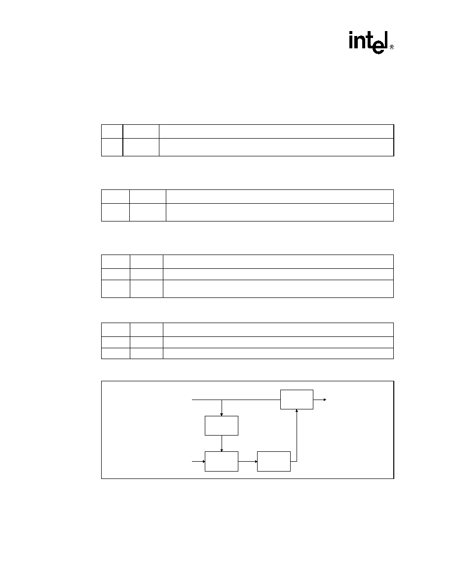
SK70740/44 -- HDSL2 Modem Chip Set
66
Datasheet
adjustment variable and is set in the associated HRFPAJ (CAh) register. "
" is the NCO clock
division ratio variable and is set in the HRFPAC (CBh) register. CW is a 16 bit control word that is
set in the HRFNCR1 (C6h) and HRFNCR2 (C7h) registers.
Table 61. NCO Control Register (MSB), HRFNCR1, R/W, Address = C6h,
Default = 17h
Bit
Name
Description
<7:0>
hrfncr1[7:0]
NCO control register MSBs. High byte of 16 bit signed value; transferred to the NCO
accumulator when high byte is written. Set to 17h for normal operation.
Table 62. NCO Control Register (LSB), HRFNCR2, R/W, Address = C7h,
Default = 5Ah
Bit
Name
Description
<7:0>
hrfncr2[7:0]
NCO control register LSBs. Low byte of 16 bit signed value; transferred to the NCO
accumulator when high byte is written. Set to 5Ah for normal operation.
Table 63. DPLL Phase Adjustment Register, HRFPAJ, R/W, Address = CAh,
Default = 2Ch
Bit
Name
Description
<7:6>
rs
Reserved. Must be set to'0' when written.
<5:0>
hrfpaj
Phase adjustment parameters. This register holds values for
up to 63. Set to 2Ch for
normal operation.
Table 64. DPLL Clock Division Ratio, HRFPAC, R/W, Address = CBh, Default =15h
Bit
Name
Description
<7:6>
rs
Reserved. Must be set to'0' when written.
<5:0>
beta
NCO clock division ratio,
. Set to 15h for normal operation.
Figure 22. RCLK Generation Circuit
Div
- 1,
,
+1
Add/Del
Control
16 bit Acc
Div
RCLK
NCOCLK
CW from
µ
C
FCLK

HDSL2 Modem Chip Set -- SK70740/44
Datasheet
67
5.6.3
Registers CCh through D1h are Reserved
Table 65. CRC Counter Register, HRFCRC, R, Address = C9h
Bit
Name
Description
<7:0>
hrfcrc
CRC error counter. The counter saturates at FFh and is reset with ercnt_rst in HRFCR.
Table 66. HDSL2 Receive Overhead Register 1, HRFHOH1, R, Address = D2h
Bit
Name
Description
7
eoc10
Receive eoc bit 10
6
eoc8
Receive eoc bit 8
5
eoc7
Receive eoc bit 7
4
eoc6
Receive eoc bit 6
3
eoc5
Receive eoc bit 5
2
eoc4
Receive eoc bit 4
1
eoc3
Receive eoc bit 3
0
eoc2
Receive eoc bit 2
Table 67. HDSL2 Receive Overhead Register 2, HRFHOH2, R, Address = D3h
Bit
Name
Description
7
eoc19
Receive eoc bit 19
6
eoc18
Receive eoc bit 18
5
eoc16
Receive eoc bit 16
4
eoc15
Receive eoc bit 15
3
eoc14
Receive eoc bit 14
2
eoc13
Receive eoc bit 13
1
eoc12
Receive eoc bit 12
0
eoc11
Receive eoc bit 11
Table 68. HDSL2 Receive Overhead Register 3, HRFHOH3, R, Address = D4h
Bit
Name
Description
7
uib
Receive unspecified indicator bit
6
eoc1
Receive eoc bit 1
5
losd
Receive loss of signal defect bit
4
eoc24
Receive eoc bit 24
3
eoc23
Receive eoc bit 23

SK70740/44 -- HDSL2 Modem Chip Set
68
Datasheet
5.6.4
Registers D6h through DCh are Reserved
5.6.5
Registers DF through FF are Reserved
2
eoc22
Receive eoc bit 22
1
eoc21
Receive eoc bit 21
0
eoc20
Receive eoc bit 20
Table 69. HDSL2 Receive Overhead Register 4, HRFHOH4, R, Address = D5h
Bit
Name
Description
7
eoc17
Receive eoc bit 17
6
segd
Receive segment defect bit
5
eoc9
Receive eoc bit 9
4
sega
Receive segment anomaly bit
3
sb1
Receive stuff bit 1
2
sb2
Receive stuff bit 2
1
sb3
Receive stuff bit 3
0
sb4
Receive stuff bit 4
Table 70. Receive Frame Sync Word (First 8 bits), HRFFSW1, R/W, Address = DDh,
Default = 00h
Bit
Name
Description
<7:0>
HRFFSW1 7:0
First 8 bits of the receive frame sync word. Bit 7 is the first bit of the FSW.
Table 71. Receive Frame Sync Word & Stuff Bits, HRFFSWSB, R/W, Address = DEh,
Default = 00h
Bit
Name
Description
<7:6>
rs
Reserved
<5:2>
HRFSB 3:0
Receive stuff bits. Bit 3 is the first stuff bit.
<1:0>
HRFFSW2 1:0
Last 2 bits of the receive frame sync word. Bit 0 is the last bit of the FSW.
Table 68. HDSL2 Receive Overhead Register 3, HRFHOH3, R, Address = D4h
Bit
Name
Description

HDSL2 Modem Chip Set -- SK70740/44
Datasheet
69
6.0
Analog Front End Test Specifications
Note:
Table 72
through
Table 77
and,
Figure 5
and
Figure 23
and represent the performance
specifications of the SK70740 AFE and are guaranteed by test except, where noted, by design. The
minimum and maximum values listed in
Table 74
through
Table 77
are guaranteed over the
recommended operating conditions specified in
Table 73
.
Table 72. Absolute Maximum Ratings
Parameter
Symbol
Min
Max
Units
Supply voltage
1
(reference to ground
2, 3
)
RVCC1, RVCC2, RVCC3, RVCC4, TVCC1, TVCC2,
TVCC3, TVCC4, BVCC, AVCC1, AVCC2, RDVCC,
TDVCC
-0.3
+6.0
V
DVCC, IOVCC1, IOVCC2
-0.3
+4.0
V
Input voltage
2, 3
,
any digital input pin
≠
-0.3
+5.5
V
Continuous output current,
any output pin
≠
≠
±25
mA
Storage temperature
T
STOR
-65
+150
∞ C
Caution: Exceeding these values may cause permanent damage. Functional operation under these
conditions is not implied. Exposure to maximum rating conditions for extended periods may affect
device reliability.
1. The maximum potential between any VCC pin must never exceed 0.3 V.
2. All GND pins must be kept at 0 V.
3. Differential voltage between any ground pins must be < 0.3 V.
Table 73. Recommended Operating Conditions
Parameter
Symbol
Min
Typ
3
Max
Units
Supply voltage
1
RVCC1, RVCC2, RVCC3, RVCC4, TVCC1, TVCC2,
TVCC3, TVCC4, BVCC, AVCC1, AVCC2, RDVCC, TDVCC
4.75
5.0
5.25
V
DVCC, IOVCC1, IOVCC2
1
3.14
3.3
3.46
V
Supply ground
2
RGND1, RGND2, RGND3, RGND4, TGND1, TGND2,
TGND3, TGND4, BGND, AGND1, AGND2, RDGND,
TDGND, IOGND1, IOGND2, DGND
-0.25
-
0.3
V
Ambient operating
temperature
T
A
-40
+85
∞ C
1. The maximum potential between any VCC pin must never exceed 0.3 V.
2. Differential voltage between any ground pins must be < 0.3 V. For design aid only; not guaranteed and not
subject to production testing.
3. Typical values are at 25∞ C and are for design aid only; not guaranteed and not subject to production
testing.
Table 74. DC Electrical Characteristics
Parameter
Symbol
Min
Typ
1
Max
Units
Test Conditions
Supply current, 5 V supplies
2
ICC5
-
98
106
mA
Full operation @ 21.5 MHz
Supply current, 3.3 V supplies
2,3
ICC3
-
11.5
12.5
mA
DVCC and IOVCC
Full power consumption
Pwr
-
525
600
mW

SK70740/44 -- HDSL2 Modem Chip Set
70
Datasheet
Digital input Low voltage
Vil
-
-
0.8
V
Digital input High voltage
Vih
2.0
-
-
V
Digital output Low voltage
Vol
-
-
0.4
V
I
OUT
= 1.6 mA
Digital output High voltage
Voh
2.4
-
-
V
I
OUT
= 400 µA
Transmitter bias voltage
(TTIP/TRING)
Vcmt
2.2
2.5
2.8
V
Receive bias voltage
(RTIP/RRING)
Vcmr
2.2
2.5
2.8
V
1. Typical values are at 25∞ C and are for design aid only; not guaranteed and not subject to production
testing.
2. Full operation at 21.5 MHz crystal frequency.
3. I/O power consumption measured with 30 pF load.
Table 75. Transmitter Electrical Parameters
Parameters
Sym
Min
Typ
Max
Unit
Test Conditions
Transmitter peak voltage TTIP, TRING
Vppd
-
2.6
-
Vp-p
(diff)
500
load single-ended or 1 k
differential
Upstream small signal bandwidth
f
3dB
325
342
360
kHz
Downstream small signal bandwidth
f
3dB
490
518
545
kHz
Table 76. Receiver Electrical Parameters
Parameters
Sym
Min
Typ
Max
Unit
Test Conditions
Input voltage range RTIP, RRING
Vi
-
2.0
10
Vp-p
(diff)
Programmable AGC gain
Av
-18
-
+3
dB
Table 77. AFE Interface Timing Specifications (see Figure 23)
Parameter
Symbol
Min
2
Typ
1
Max
2
Unit
Test Conditions
REFCLK frequency (21.500 MHz crystal)
-
-
10.75
-
MHz
REFCLK duty cycle
-
45
-
55
%
Clock oscillator input (XTALI) Low voltage
4
Vil
-
-
0.8
V
Clock oscillator input (XTALI) High voltage
4
Vih
2.0
-
-
V
1. Typical values are at 25∞ C and are for design aid only; not guaranteed and not subject to production
testing.
2. Measured with 30pF loads on all outputs.
3. Not subjected to production testing. For design aid only.
4. If XTALI pin is overdriven by a clock signal, then XTALO pin must be grounded. XTALI pin may be driven by
a 3.3 V or 5.0 V clock oscillator regardless of the supply voltage applied at IOVCC1 and IOVCC2.
Table 74. DC Electrical Characteristics (Continued)
Parameter
Symbol
Min
Typ
1
Max
Units
Test Conditions

HDSL2 Modem Chip Set -- SK70740/44
Datasheet
71
DAC<3:0>, RSDO and ACE setup time
Tts
30
65
-
ns
Typical values are
based on typical data
that Transceiver can
provide.
DAC<3:0>, RSDO and ACE hold time
Tth
0
15
-
ns
REFCLK to ADC<5:0> valid data
3
Tvd
-
5
20
ns
REFCLK to RSDI valid data
Tvdi
-
5
15
ns
Figure 23. AFE Interface Timing
Table 77. AFE Interface Timing Specifications (see Figure 23)
Parameter
Symbol
Min
2
Typ
1
Max
2
Unit
Test Conditions
1. Typical values are at 25∞ C and are for design aid only; not guaranteed and not subject to production
testing.
2. Measured with 30pF loads on all outputs.
3. Not subjected to production testing. For design aid only.
4. If XTALI pin is overdriven by a clock signal, then XTALO pin must be grounded. XTALI pin may be driven by
a 3.3 V or 5.0 V clock oscillator regardless of the supply voltage applied at IOVCC1 and IOVCC2.
T
TH
T
TS
V
IH
V
IL
ADC<5:0>
V
OH
V
OL
RSDI
V
OH
V
OL
T
VD
T
VDI
REFCLK
V
IH
V
IL
ACE, RSDO, DAC<3:0>

SK70740/44 -- HDSL2 Modem Chip Set
72
Datasheet
7.0
Transceiver/Framer Test Specifications
Note:
Table 78
through
Table 84
and
Figure 24
through
Figure 27
represent the performance
specifications of the SK70744 Transceiver/Framer and are guaranteed by test except, where noted,
by design. The minimum and maximum values listed in
Table 80
through
Table 84
are guaranteed
over the recommended operating conditions specified in
Table 79
.
Table 78. Absolute Maximum Ratings
Parameter
Symbol
Min
Max
Unit
Digital Supply voltage
1
(reference to ground
2
)
VCC1, VCC2, VCC3, VCC4, VCCPLL
-0.3
+4.0
V
I/O Supply voltage
1
(reference to ground
2
)
IOVCC1, IOVCC2, IOVCC3, IOVCC4
-0.3
+4.0
V
Input voltage
2
, any input pin
≠
- 0.3
+5.5
V
Continuous output current, any output pin
≠
≠
±25
mA
Storage temperature
T
STOR
-65
+150
∞ C
Caution: Exceeding these values may cause permanent damage. Functional operation under these
conditions is not implied. Exposure to maximum rating conditions for extended periods may affect
device reliability.
1. The maximum potential between any VCC must never exceed ±1.2 V.
2. GND4 = 0V, GND3 = 0V; GND2 = 0V; GND1 = 0V.
Table 79. Recommended Operating Conditions
Parameter
Symbol
Min
Typ
3
Max
Unit
Supply voltage
1
IOVCC1, IOVCC2, IOVCC3, IOVCC4
3.14
3.30
3.46
V
VCC1, VCC2, VCC3, VCC4
VCCPLL
2.38
2.50
2.63
V
Supply ground
2
GND1, GND2, GND3, GND4
GNDPLL
IOGND1, IOGND2, IOGND3, IOGND4
-0.25
-
+0.3
V
Ambient operating temperature
T
A
-40
-
+85
∞C
1. The maximum potential between any VCC pin must never exceed 0.3 V.
2. Differential voltage between any ground pins must be < 0.3 V. For design aid only; not guaranteed and not
subject to production testing.
3. Typical values are at 25∞ C and are for design aid only; not guaranteed and not subject to production
testing.
Table 80. DC Electrical Characteristics
Parameter
Sym
Min
Typ
1
Max
Unit
Test Conditions
Supply current (2.5 V supply)
I
CC
2
≠
320
400
mA
Supply current (3.3 V supply)
I
CC
3
45
55
mA
Input Low voltage
V
IL
≠
≠
0.8
V
1. Typical values are at 25∞ C and are for design aid only; not guaranteed and not subject to production
testing.
2. Applies to I/O pins when configured as inputs.
3. Applies to tristated pins.
4. Does not include current through internal or external pull up/down resistance.

HDSL2 Modem Chip Set -- SK70740/44
Datasheet
73
Input High voltage
V
IH
2.0
≠
≠
V
Output Low voltage
V
OL
≠
≠
0.4
V
I
OUT
=1.6 mA
Output High voltage
V
OH
2.4
≠
≠
V
I
OUT
=400
µ
A
Input leakage current
2, 4
I
IL
≠
≠
±50
µ
A
0 < V
IN
< V
CC2
Tristate leakage current
3, 4
I
TOL
≠
≠
±30
µ
A
0 < V < V
CC2
Input capacitance (individual
pins)
C
IN
≠
12
≠
pF
Load capacitance DAC<3:0>
C
LREF
≠
≠
15
pF
Table 81. AFE Data Interface Timing Specifications (see Figure 24)
Parameter
Symbol
Min
Typ
1
Max
Unit
REFCLK frequency (21.5 MHz Crystal)
≠
≠
10.750
≠
MHz
REFCLK duty cycle
≠
45
≠
55
%
ADC<5:0> to rising edge of REFCLK
T
DS
60
≠
≠
ns
REFCLK rising edge to ADC<5:0> hold time
T
DH
0
≠
≠
ns
DAC<3:0> delay from rising edge of REFCLK
T
AD
≠
≠
40
ns
1. Typical values are at 25∞ C and are for design aid only; not guaranteed and not subject to production
testing.
2. Measured with 15 pF load.
Figure 24. AFE Data Interface Relative Timing
Table 80. DC Electrical Characteristics (Continued)
Parameter
Sym
Min
Typ
1
Max
Unit
Test Conditions
1. Typical values are at 25∞ C and are for design aid only; not guaranteed and not subject to production
testing.
2. Applies to I/O pins when configured as inputs.
3. Applies to tristated pins.
4. Does not include current through internal or external pull up/down resistance.
REFCLK
DAC <3:0>
ADC <5:0>
T
DS
T
DH
T
AD

SK70740/44 -- HDSL2 Modem Chip Set
74
Datasheet
Table 82. AFE Control Interface Timing Specifications (see Figure 5 and Figure 25)
Parameter
Symbol
Min
Typ
1
Max
Unit
RSDI setup time to REFCLK rising edge
Tss
45
≠
≠
ns
REFCLK rising edge to RSDI hold time
Tsh
5
≠
≠
ns
RSDO delay from REFCLK rising edge
Tsd
≠
≠
35
ns
ACE falling edge delay from REFCLK rising edge
Tace
≠
≠
40
ns
1. Typical values are at 25∞ C and are for design aid only; not guaranteed and not subject to production
testing.
2. Measured with 15 pF load.
Figure 25. AFE Control Interface Relative Timing
Table 83. TDM Interface Timing Specifications - T1 Transport Mode (see Figure 26)
Parameter
Symbol
Min
Typ
1
Max
Unit
TCLK, RCLK frequency
2
≠
1.5438
1.5440
1.5442
MHz
TCLK, RCLK duty cycle
≠
40
≠
60
%
TFSYNC pulse width
T
FS
≠
1/f
TCLK
≠
ns
RFSYNC pulse width
T
FS
≠
1/f
RCLK
≠
ns
TSER setup time to TCLK falling edge
T
DS
10
≠
≠
ns
TSER hold time from TCLK falling edge
T
DH
20
≠
≠
ns
RSER delay from RCLK rising edge
T
RD
≠
≠
15
ns
1. Typical values are at 25∞ C and are for design aid only; not guaranteed and not subject to production
testing.
2. Min. and Max values are for design aid only; not guaranteed and not subject to production testing.
BIT 15
BIT 14
BIT 13
BIT 12
BIT 0
REFCLK
ACE
RSDI
RSDO
T
SS
T
SH
T
SD
T
ACE
BIT 15
BIT 14
BIT 13
BIT 12
BIT 0

HDSL2 Modem Chip Set -- SK70740/44
Datasheet
75
Figure 26. TDM Interface Timing - T1 Transport Mode
Table 84. Transceiver/Framer Reset Timing Specification
Parameter
Symbol
Min
Max
Unit
Test Conditions
RST Low pulse width
Trpwl
200
≠
ns
Table 85. Intel Bus Parallel I/O Timing Characteristics (see Figure 27)
Parameter
Sym
Min
Max
Unit
Test Conditions
ALE pulse width
Tale
10
≠
ns
Address valid to ALE falling edge setup time
Tas
10
≠
ns
ALE falling edge to address hold time
Tah
10
≠
ns
CS falling edge to RD falling edge
Tcsr
40
≠
ns
CS falling edge to WR falling edge
Tcsw
40
≠
ns
RD Low pulse width
Trw
80
≠
ns
RD falling edge to data valid
Trd
≠
80
ns
Data high impedance after RD rising edge
Trdz
≠
40
ns
WR Low pulse width
Tww
80
≠
ns
Write data setup time after WR falling edge
Tds
10
≠
ns
Read data hold time after RD rising edge
Trdh
0
≠
ns
Write data hold time after WR rising edge
Twdh
10
≠
ns
RD rising edge to ALE rising edge
Trdal
40
-
ns
TSER
TFSYNC
RSER
TCLK
HDSL2 Symbol Period
Bit 1
Bit 0
Bit 2
Bit 2
Bit 1
Bit 0
Bit 2
Bit 2
T
TO
T
TI
RCLK
RFSYNC
T
RD
T
RFS
T
TFS
T
DS
T
DH

SK70740/44 -- HDSL2 Modem Chip Set
76
Datasheet
Table 86. Motorola Bus Parallel I/O Timing Characteristics (see Figure 27)
Parameter
Symbol
Min
Max
Unit
Test Conditions
DS Low pulse width
T
H
130
≠
ns
Read data valid time after DS rising edge
T
RDH
0
≠
ns
DS rising edge to write data hold time
T
WDH
5
≠
ns
Valid address to DS falling edge
T
AS
10
≠
ns
DS falling edge to valid address hold time
Tah
10
≠
ns
Write data setup time after DS falling edge
T
DS
10
≠
ns
DS falling edge to valid data
T
RD
≠
120
ns
Data high impedance after CS or DS are asserted High
T
RDZ
≠
40
ns
Required High time of DS
T
DSH
60
≠
ns

HDSL2 Modem Chip Set -- SK70740/44
Datasheet
77
Figure 27. Parallel Microprocessor Bus Interface Timing
ALE
RD
AD<7:0>
CS
Address
Data
80C51 Read Cycle Timing
T
ALE
T
AS
T
AH
T
RW
T
DRZ
T
RD
T
CSR
T
RDAL
T
RDH
80C51 Write Cycle Timing
ALE
Address
T
ALE
T
AS
T
AH
T
WW
Data
T
WDH
WR
AD<7:0>
CS
68000 Read Cycle Timing
R / W
DS
CS
AD<7:0>
Read Data
A<7:0>
Address
T
H
T
DSH
T
RDZ
T
RDH
T
RD
68000 Write Cycle Timing
R / W
DS
CS
A<7:0>
Address
T
H
T
DSH
T
CSW
Address
T
AS
T
AH
Address
T
AS
T
AH
CS and R/W must be valid by DS
T
DS
T
DS
T
WDH
Write Data
AD<7:0>

SK70740/44 -- HDSL2 Modem Chip Set
78
Datasheet
8.0
Mechanical Specifications
Figure 28. 64 Pin QFP Package
e/2
B
PIN DETAIL
L1
L
3
3
A
A2
A1
D
D1
D3
E
E1
E3
64-Pin Quad Flat Pack
∑
Part Number SK70740HE
∑
Extended Temperature Range (-40 ∞C to 85 ∞C)
Dim
Millimeters
Min
Max
A
≠
3.00
A1
0.10
0.25
A2
2.55
2.75
B
0.30
0.45
D
17.65
18.15
D1
13.95
14.05
D3
12.00 REF.
E
17.65
18.15
E1
13.95
14.05
E3
12.00 REF.
e
0.80 BSC.
L
0.65
0.95
L1
1.95 REF.
3
12
∞
16
∞
Dimensions conform to JEDEC
registered outline MO-112.

HDSL2 Modem Chip Set -- SK70740/44
Datasheet
79
Figure 29. 100 Pin QFP Package
100 -Pin Quad Flat Pack
∑
Part Number SK70744HE
∑
Extended Temperature Range (-40 ∞C to 85 ∞C)
Dim
Millimeters
Min
Max
A
≠
3.10
A1
0.10
0.36
A2
2.57
2.87
B
0.22
0.38
D
23.65
24.15
D1
19.90
20.10
D3
18.85 REF.
E
17.65
18.15
E1
13.90
14.10
E3
12.35 REF.
e
0.65 BSC.
L
0.73
1.03
L1
1.95 REF.
3
12∞
16∞
Dimensions conform to JEDEC
registered outline MO-112.
D
D1
D3
E
E1
E3
L1
L
3
3
A
A2
A1
e/2
B
PIN DETAIL
