 | –≠–ª–µ–∫—Ç—Ä–æ–Ω–Ω—ã–π –∫–æ–º–ø–æ–Ω–µ–Ω—Ç: FM704A | –°–∫–∞—á–∞—Ç—å:  PDF PDF  ZIP ZIP |

B3-3
DESCRIPTION
Interpoint's FM-704ATM EMI Filter and Transient Suppression
Module combines EMI filtering and transient protection to handle the
demanding requirements of military, aerospace and industrial appli-
cations. As an EMI filter the FM-704A filter reduces the reflected
ripple current from DC/DC switching converters. As a protection
module, it suppresses input transients on the power bus to protect
the converter and other downstream components.
MIL-STD N
OISE
M
ANAGEMENT
When used in conjunction with Interpoint converters, the FM-704A
EMI filter reduces reflected input ripple current by a minimum of 60
dB at 500 kHz and 55 dB at 1 MHz (see Figures and Electrical
Characteristics table). This attenuation gives the converter/filter
combination performance exceeding MIL-STD-461C's CE03 test.
Although the FM-704A filter effectively attenuates the ripple gener-
ated by switching converters, it will not suppress RF applied to its
input terminals.
T
EMPERATURE
O
PERATION
FM-704A filters are rated to operate from -55∞C to +125∞C base-
plate temperature. To meet MIL-STD-1275A and MIL-STD-704A
requirements, derate output power linearly from 40 watts at 105∞C
to 25 watts at 125∞C. See Figure 9.
P
ROTECTION
To provide protection for itself and converters, the FM-704A filter
blocks transients as required by the following standards:
MIL-STD-704A
Panavia SP-P-90001
MIL-STD-461B&C
British Standard BS3G100
MIL-STD-1275
Civil Aircraft D0160B
Refer to the Electrical Characteristics table on the following page for
more information.
Reverse polarity spikes of up to 100 V will not damage the filter,
however the spikes will not be blocked by the filter.
I
NTERNAL
P
OWER
D
ISSIPATION
To keep internal power dissipation to safe operating levels, the input
current should never exceed 2.5 amps at 16 Vin or 1.0 amp at 40
Vin. When the FM-704A filter is used with PWM (Pulse Width
Modulated) converters, I
line
will vary as Power / V
line
and 2.5 amps
maximum at 16 Vin will reduce to approximately 1 amp maximum
at 40 Vin. The maximum value allowed may be less than 1 amp as
determined by line transients and the safe operating area of Figure
9.
Figure 9 illustrates the maximum allowed internal dissipation for the
FM-704A filter. To calculate watts dissipated, subtract 40 volts from
the transient (VT) to determine the maximum voltage across the
filter and multiply the result by the current (the filter's output power,
Pout divided by 40).
W = (V
T
- 40) x P
out
/40
For example, with 20 watts output and a transient of 400 volts:
W = (400 - 40) x 20/40 = 180
The curve of Figure 9 shows that 180 W can be dissipated for up to
4 milliseconds.
F
EATURES
The inhibit function allows the FM-704A filter to be used as a high-
side switch. When the inhibit terminal (pin 6) is left open or pulled
high, the FM-704A filter is enabled. When the terminal is grounded,
the filter shuts off output power.
A soft start function helps reduce inrush current and start-up over-
shoot when the filter is initially powered or when it is released from
the inhibit mode.
An undervoltage lockout feature shuts off output power when input
voltage falls below a specified level. Refer to Figure 8 for more infor-
mation.
L
AYOUT
R
EQUIREMENTS
The case of the filter must be connected to the case of the converter
through a low impedance connection to minimize EMI.
EMI I
NPUT
F
ILTER AND
T
RANSIENT
S
UPPRESSION
M
ODULE
, 28 V
OLT
I
NPUT
FM-704A EMI FILTER
40 WATT
F
EATURES
∑ ≠55∞C to +125∞C operation
∑ 16 to 40 VDC input
∑ Up to 60 dB attenuation
at 500 kHz.
∑ Active transient suppression
∑ Undervoltage lockout
∑ Inhibit function
∑ Compliant to
MIL-STD-461C, CE03
Size (max): 2.910 x 1.125 x 0.400 inches (73.91 x 28.58 x 10.16 mm)
See Section B8, case K1, for dimensions.
Weight:
40 grams maximum
Screening: Standard, ES, or 883 (Class H). See Section C2 for screening
options, see Section A5 for ordering information.
MODEL
FM-704A
40 Watts

ABSOLUTE MAXIMUM RATINGS
INHIBIT
RECOMMENDED OPERATING CONDITIONS
TYPICAL CHARACTERISTICS
Input Voltage
∑ 16 to 40 VDC continuous for 40 W load
Lead Soldering Temperature (10 sec per lead)
∑ 300∞C
Storage Temperature Range (Case)
∑ ≠65∞C to +150∞C
B3-4
FM-704A EMI FILTER
40 WATT
Input Voltage Range
∑ 16 to 40 VDC continuous for 40 W load
Case Operating Temperature (Tc)
∑ ≠55∞C to +125∞C
Derating Output Power
∑ Linearly from 40 W at 105∞C to 25 W at 125∞C to meet
MIL-STD-1275A (AT) and MIL-STD-704A
Electrical Characteristics: 25∞C Tc, nominal Vin, unless otherwise specified.
EMI I
NPUT
F
ILTERS
Capacitance
∑ 0.017 µF max, any pin to case
Undervoltage lockout
∑ 7 VDC min, 15 VDC max
Isolation
∑ 100 megohm minimum at 500 V
∑ Any pin to case, except case pin
Inhibit Pin Voltage (unit enabled)
∑ 5.5 V max
Inhibit TTL Open Collector
∑ Logic low (output disabled)
Logic low voltage
0.8 V
Logic low inhibit pin current 0.6 mA max
∑ Referenced to input common
∑ Logic high (output enabled)
Open collector
FM-704A
PARAMETER
CONDITIONS
MIN TYP MAX
UNITS
INPUT VOLTAGE
NO LOAD
0
28
40
40 W LOAD
16
28
40
VDC
UNDERVOLTAGE LOCKOUT
7
--
15
INPUT CURRENT
16 V
IN
--
--
2.5
A
40 V
IN
--
--
1.0
NO LOAD
--
--
5
mA
INHIBITED --
--
2
INPUT SURGE
40 W, 100 V, 0.5
Z
S
, 60 ms
1
42
--
48
V
OUT
INPUT SPIKE
40 W, 400 V, 0.5
Z
S
, 5 µs
2
--
--
48
V
OUT
40 W, 600 V, 50
Z
S
, 10 µs
3
--
--
48
DIFFERENTIAL MODE
500 kHz
60
--
--
dB
NOISE REJECTION
1 MHz
55
--
--
DC RESISTANCE (R
DC
)
Tc = 25∞C
--
--
0.45
OUTPUT VOLTAGE
STEADY STATE
V
OUT
= V
IN
- I
IN
(R
DC
)
VDC
INHIBITED --
--
1
OUTPUT CURRENT
16 V
IN
--
--
2.5
A
40 V
IN
--
--
1.0
INTERNAL POWER
PEAK
DISSIPATION
105∞C
--
--
1000
125∞C
--
--
500
W
CONTINUOUS ( > 10 SEC.)
105∞C
--
--
30
125∞C
--
--
15
Notes
1. Meets MIL-STD-1275A (AT) Surge and Figure 8 and 9 of MIL-STD-704A. For these standards derate output power linearly from 40 W at 105∞C to 25
W at 125∞C.
2. Meets Panavia SP-P-90001, British Standard BS3G100 and Civil Aircraft D0160 Standards.
3. Meets MIL-STD-461C 1.2 CS06 limits.
MODEL NUMBERING KEY
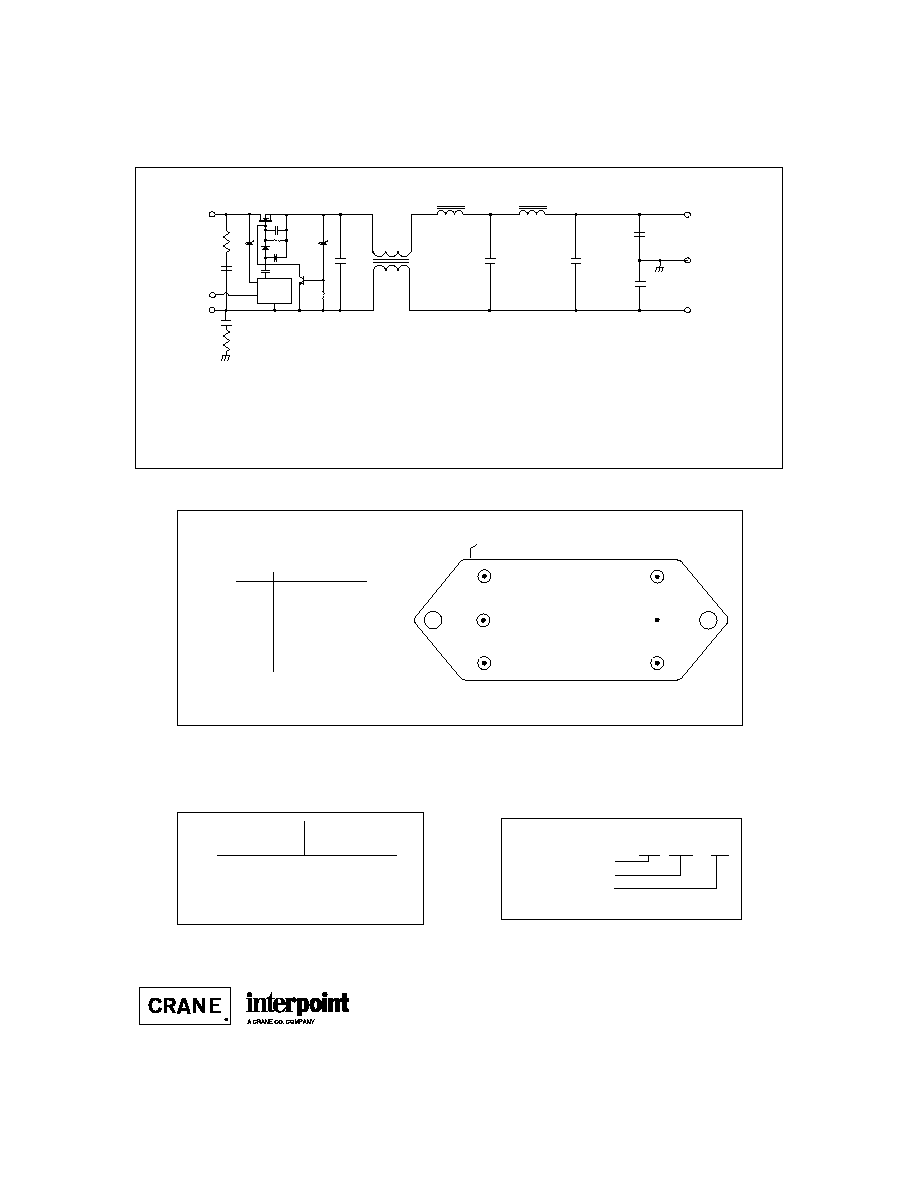
PIN OUT
1
2
4
5
BOTTOM VIEW
FM-704A
Dot on top of package indicates pin one
3
6
FM - 704A / 883
Base Model
MIL-STD-704A Reference
Screening
(Standard screening has no designator
in this position.)
B3-5
EMI I
NPUT
F
ILTERS
See Section B8, case K1 for dimensions.
Pin
Designation
1
Positive Input
2
Positive Output
3
Case Ground
4
Output Common
5
Input Common
6
Inhibit
F
IGURE
2: P
IN
O
UT
DSCC NUMBER
DSCC D
RAWING
(5915)
94028-01HXC
FM-704A F
ILTER
S
IMILAR
P
ART
FM-704A/883
For exact specifications for a DSCC product, refer to the
DSCC drawing. See Section A3, "SMD/DSCC Lists", for
more information.
0.068
F
Positive
Input
Input
Common
Positive
Output
Output
Common
FM-704A
3.6 H
6 F
25
3.6 H
6 F
3300
pF
15
3300 pF / 500V
390 H
Inhibit
Oscillator
3300 pF
500V
6600 pF
500V
Case
The case ground connection between the filter and the converter should be as low an impedance as possible
to minimize EMI. Direct contact of baseplate to chassis ground provides the lowest impedance.
F
IGURE
1: S
CHEMATIC
≠ T
YPICAL
V
ALUES
FM-704A EMI FILTER
40 WATT
B3-6
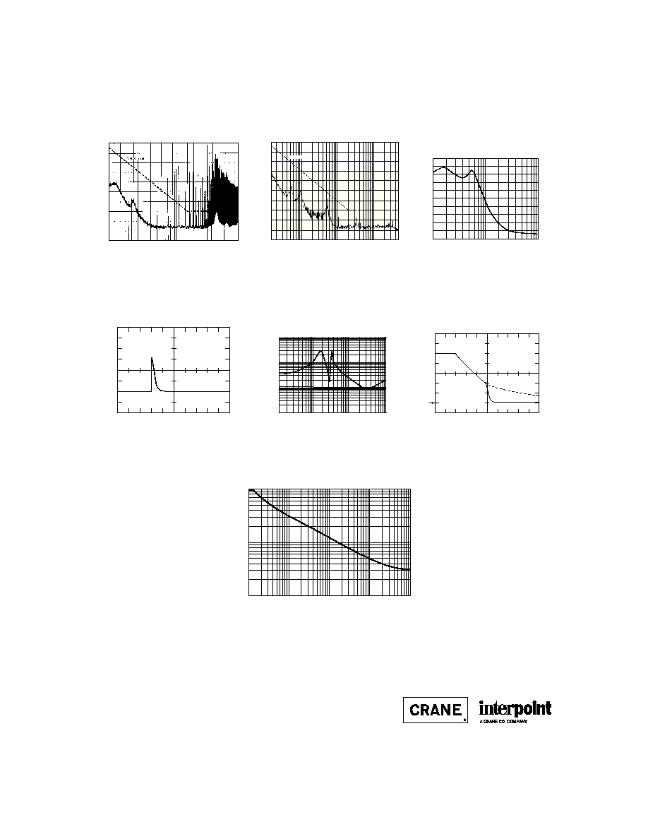
Typical Performance Curves: 25∞C Tc , nominal Vin, unless otherwise specified.
EMI I
NPUT
F
ILTERS
FM-704A EMI FILTER
40 WATT
F
IGURE
6
F
IGURE
8
1 A / div.
5 ms / div.
FM≠704A
15 watt load
5 V/ div.
100 ms / div.
FM≠704A
0 volts
for Vout
V
in
V
out
V
in and
V
out
90
70
50
30
.015
0.1
1
10
50
10
EMISSION LEVEL (dmA)
FREQUENCY (MHz)
F
IGURE
3
90
70
50
30
.015
.1
1
10
50
10
EMISSION LEVEL (dmA)
FREQUENCY (MHz)
CE03 Limit
F
IGURE
4
0.10
1.00
10.00
FREQUENCY (Hz)
1 K
10 K
100 K
1 M
0.01
IMPEDANCE (Z, OHMS)
F
IGURE
7
F
IGURE
5
≠40
≠20
0
20
FREQUENCY (Hz)
10 K
100 K
1 M
-80
GAIN (dB)
≠60
10
1000
100
0.1
1
10
100
1000
WATTS
TIME (ms)
F
IGURE
9
MHF+ Converter Without Filter
MHF+ Converter With
FM-704A Filter
Maximum Allowed Internal Power Dissipation
105∞C case temperature
Derate power linearly to 50% at 125∞C. Operation below this curve
ensures a maximum junction temperature rise of 40∞C or less.
Differential Mode Response
Inrush Current
Typical Output Impedance (Z)
With Input Shorted
Undervoltage Lockout
25021-001-DTS Rev A
DQ# 4001
All technical information is believed to be accurate, but no responsibility is
assumed for errors or omissions. Interpoint reserves the right to make changes in
products or specifications without notice. FM-704A is a trademark of Interpoint.
Copyright © 1992 - 1999 Interpoint. All rights reserved.

B8-26
CASE K
C
ASES
Materials
Header Case K1 - K3
Cold Rolled Steel/Nickel/Gold
Cases K4 - K8
Cold Rolled Steel/Nickel/Tin
Cover
Case K1 - K3
Kovar/Nickel
Case K4 - K8
Cold Rolled Steel/Nickel/Tin
Pins
#52 alloy (all cases)
Case K1, K2, and K3 (except MHV Series Single and Dual)
ceramic seal
Cases K4 - K8 and MHV Series Single and Dual (K3)
compression glass seal
Case dimensions in inches (mm)
Tolerance
±
0.005 (0.13) for three decimal places
±
0.01 (0.2) for two decimal places
unless otherwise specified
CASE K
BOTTOM VIEW
See Figures 42 - 48
for pin configuration
CAUTION
Heat from reflow or wave soldering may damage
the device. Solder pins individually with heat
application not exceeding 300
∞
C for 10 seconds
per pin.
Flange Thickness:
Cases K1, K2, K3 and MLP Series (K5)
0.060 (1.52)
Cases K4, K5 (except MLP Series), K6, K7, and K8
0.067 +0.005/-0.007 (1.70 +0.13/-0.8)
1.125 max
(28.58)
2.910 max
(73.91)
Dot on top of case indicates pin one
F
IGURE
41: C
ASE
K M
AXIMUM
D
IMENSIONS